- Table of Contents
-
- H3C Low-End and Mid-Range Ethernet Switches Configuration Examples(V1.01)
- 00-1Cover
- 01-Login Configuration Guide
- 02-VLAN Configuration Guide
- 03-GVRP Configuration Guide
- 04-Voice VLAN Configuration Guide
- 05-IP Addressing and Performance Configuration Guide
- 06-QinQ Configuration Guide
- 07-BPDU Tunnel Configuration Guide
- 08-VLAN Mapping Configuration Guide
- 09-MAC Address Table Management Configuration Guide
- 10-Link Aggregation Configuration Guide
- 11-IP Source Guard Configuration Guide
- 12-DLDP Configuration Guide
- 13-MSTP Configuration Guide
- 14-IPv4 Routing Configuration Guide
- 15-IPv6 Configuration Guide
- 16-IPv6 Routing Configuration Guide
- 17-IPv4 Multicast Configuration Guide
- 18-IPv6 Multicast Configuration Examples
- 19-802.1x Configuration Guide
- 20-AAA Configuration Guide
- 21-MAC Authentication Configuration Guide
- 22-Portal Configuration Guide
- 23-ARP Configuration Guide
- 24-DHCP Configuration Guide
- 25-ACL Configuration Guide
- 26-QoS Configuration Guide
- 27-Port Mirroring Configuration Guide
- 28-Cluster Management Configuration Guide
- 29-SNMP-RMON Configuration Guide
- 30-NTP Configuration Guide
- 31-FTP-TFTP Configuration Guide
- 32-UDP Helper Configuration Guide
- 33-Information Center Configuration Guide
- 34-DNS Configuration Guide
- 35-File System Management Configuration Guide
- 36-Remote Upgrade Configuration Guide
- 37-NQA Configuration Guide
- 38-VRRP Configuration Guide
- 39-SSH Configuration Guide
- 40-Port Security Configuration Guide
- 41-Port Isolation Configuration Guide
- 42-LLDP Configuration Guide
- 43-MCE Configuration Guide
- 44-PoE Configuration Guide
- 45-OAM Configuration Guide
- 46-Connectivity Fault Detection Configuration Guide
- 47-RRPP Configuration Guide
- 48-sFlow Configuration Guide
- 49-SSL-HTTPS Configuration Guide
- 50-PKI Configuration Guide
- 51-Track Configuration Guide
- 52-EPON-OLT Configuration Guide
- 53-Smart Link Configuration Guide
- 54-MPLS Configuration Guide
- Related Documents
-
| Title | Size | Download |
|---|---|---|
| 54-MPLS Configuration Guide | 623.27 KB |
Table of Contents
Networking and Configuration Requirements
2 MPLS L2VPN Configuration Guide
Guide for Configuring a Remote CCC Connection
Networking and Configuration Requirements
Networking and Configuration Requirements
Configuring Martini MPLS L2VPN
Networking and Configuration Requirements
Configuring Kompella MPLS L2VPN
Networking and Configuration Requirements
3 MPLS L3VPN Configuration Guide
Networking and Configuration Requirements
Configuring Inter-Provider VPN Option A
Networking and Configuration Requirements
Configuring Inter-Provider VPN Option B
Networking and Configuration Requirements
Configuring Inter-Provider VPN Option C
Networking and Configuration Requirements
Networking and Configuration Requirements
Networking and Configuration Requirements
Networking and Configuration Requirements
Configuring BGP AS Number Substitution
Networking and Configuration Requirements
MPLS Configuration Guide
Network Diagram
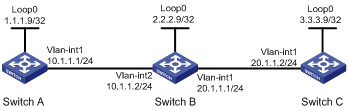
Figure 1-1 Network diagram for configuring LDP sessions
Networking and Configuration Requirements
l Switch A, Switch B, and Switch C all support MPLS. Configure them to run OSPF.
l Two local LDP sessions are established. One is between Switch A and Switch B, and the other is between Switch B and Switch C.
l A remote LDP session is established between Switch A and Switch C.
l The three switches establish an LSP using the local LDP sessions.
Applicable Product Matrix
|
Product series |
Software version |
Hardware version |
|
S7500E Series Ethernet Switches |
Release 6300 |
LSQ1SRP1CB SRPU(s), or exclusively EA series LPUs |
Configuration Procedure
1) Configure the IP addresses of the interfaces
Configure the IP addresses and masks of the interfaces including the VLAN interfaces and loopback interfaces as required in Figure 1-1. The detailed configuration procedure is omitted here.
2) Configure the routes for OSPF to advertise
# Configure Switch A.
<Sysname> system-view
[Sysname] sysname SwitchA
[SwitchA] ospf
[SwitchA-ospf-1] area 0
[SwitchA-ospf-1-area-0.0.0.0] network 1.1.1.9 0.0.0.0
[SwitchA-ospf-1-area-0.0.0.0] network 10.1.1.0 0.0.0.255
[SwitchA-ospf-1-area-0.0.0.0] quit
[SwitchA-ospf-1] quit
# Configure Switch B.
<Sysname> system-view
[Sysname] sysname SwitchB
[SwitchB] ospf
[SwitchB-ospf-1] area 0
[SwitchB-ospf-1-area-0.0.0.0] network 2.2.2.9 0.0.0.0
[SwitchB-ospf-1-area-0.0.0.0] network 10.1.1.0 0.0.0.255
[SwitchB-ospf-1-area-0.0.0.0] network 20.1.1.0 0.0.0.255
[SwitchB-ospf-1-area-0.0.0.0] quit
[SwitchB-ospf-1] quit
# Configure Switch C.
<Sysname> system-view
[Sysname] sysname SwitchC
[SwitchC] ospf
[SwitchC-ospf-1] area 0
[SwitchC-ospf-1-area-0.0.0.0] network 3.3.3.9 0.0.0.0
[SwitchC-ospf-1-area-0.0.0.0] network 20.1.1.0 0.0.0.255
[SwitchC-ospf-1-area-0.0.0.0] quit
[SwitchC-ospf-1] quit
After completing the above configurations, you will see that every switch has learned the routes to other switches if you execute the display ip routing-table command. The following takes Switch A as an example:
[SwitchA] display ip routing-table
Routing Tables: Public
Destinations : 9 Routes : 9
Destination/Mask Proto Pre Cost NextHop Interface
1.1.1.9/32 Direct 0 0 127.0.0.1 InLoop0
2.2.2.9/32 OSPF 10 1563 10.1.1.2 Vlan1
3.3.3.9/32 OSPF 10 3125 10.1.1.2 Vlan1
10.1.1.0/24 Direct 0 0 10.1.1.1 Vlan1
10.1.1.1/32 Direct 0 0 127.0.0.1 InLoop0
10.1.1.2/32 Direct 0 0 10.1.1.2 Vlan1
20.1.1.0/24 OSPF 10 3124 10.1.1.2 Vlan1
127.0.0.0/8 Direct 0 0 127.0.0.1 InLoop0
127.0.0.1/32 Direct 0 0 127.0.0.1 InLoop0
Now, OSPF adjacency should have been established between Switch A and Switch B and between Switch B and Switch C respectively. If you execute the display ospf peer verbose command, you will find that the neighbors are in the state of Full. The following takes Switch A as an example:
[SwitchA] display ospf peer verbose
OSPF Process 1 with Switch ID 1.1.1.9
Neighbors
Area 0.0.0.0 interface 10.1.1.1(Vlan-interface1)'s neighbors
Router ID: 2.2.2.9 Address: 10.1.1.2 GR State: Normal
State: Full Mode:Nbr is Master Priority: 1
DR: None BDR: None MTU: 1500
Dead timer due in 39 sec
Neighbor is up for 00:02:13
Authentication Sequence: [ 0 ]
3) Configure MPLS basic capability and enable LDP
# Configure Switch A.
[SwitchA] mpls lsr-id 1.1.1.9
[SwitchA] mpls
[SwitchA-mpls] quit
[SwitchA] mpls ldp
[SwitchA-mpls-ldp] quit
[SwitchA] interface vlan-interface 1
[SwitchA-Vlan-interface1] mpls
[SwitchA-Vlan-interface1] mpls ldp
[SwitchA-Vlan-interface1] quit
# Configure Switch B.
[SwitchB] mpls lsr-id 2.2.2.9
[SwitchB] mpls
[SwitchB-mpls] quit
[SwitchB] mpls ldp
[SwitchB-mpls-ldp] quit
[SwitchB] interface vlan-interface 1
[SwitchB-Vlan-interface1] mpls
[SwitchB-Vlan-interface1] mpls ldp
[SwitchB-Vlan-interface1] quit
[SwitchB] interface vlan-interface 2
[SwitchB-Vlan-interface2] mpls
[SwitchB-Vlan-interface2] mpls ldp
[SwitchB-Vlan-interface2] quit
# Configure Switch C.
[SwitchC] mpls lsr-id 1.1.1.9
[SwitchC] mpls
[SwitchC-mpls] quit
[SwitchC] mpls ldp
[SwitchC-mpls-ldp] quit
[SwitchC] interface vlan-interface 1
[SwitchC-Vlan-interface1] mpls
[SwitchC-Vlan-interface1] mpls ldp
[SwitchC-Vlan-interface1] quit
After completing the above configurations, local sessions should have been established between Switch A and Switch B and between Switch B and Switch C. You can execute the display mpls ldp session command to check whether the local sessions have been established, or use the display mpls ldp peer command to check the peers. The following takes Switch A as an example:
[SwitchA] display mpls ldp session
LDP Session(s) in Public Network
Total number of sessions: 1
----------------------------------------------------------------
Peer-ID Status LAM SsnRole FT MD5 KA-Sent/Rcv
----------------------------------------------------------------
2.2.2.9:0 Operational DU Passive Off Off 5/5
----------------------------------------------------------------
LAM : Label Advertisement Mode FT : Fault Tolerance
[SwitchA] display mpls ldp peer
LDP Peer Information in Public network
Total number of peers: 1
-----------------------------------------------------------------
Peer-ID Transport-Address Discovery-Source
----------------------------------------------------------------
2.2.2.9:0 2.2.2.9 Vlan-interface1
----------------------------------------------------------------
4) Configure the remote LDP session
# Configure Switch A.
[SwitchA] mpls ldp remote-peer peerc
[SwitchA-mpls-ldp-remote-peerc] remote-ip 3.3.3.9
[SwitchA-mpls-ldp-remote-peerc] quit
# Configure Switch C.
[SwitchC] mpls ldp remote-peer peera
[SwitchC-mpls-ldp-remote-peera] remote-ip 1.1.1.9
[SwitchC-mpls-ldp-remote-peera] quit
After completing the above configurations, you will find by issuing the following commands on Switch A that the remote LDP session with Switch C is already established:
[SwitchA] display mpls ldp session
LDP Session(s) in Public Network
Total number of sessions: 2
----------------------------------------------------------------
Peer-ID Status LAM SsnRole FT MD5 KA-Sent/Rcv
----------------------------------------------------------------
2.2.2.9:0 Operational DU Passive Off Off 35/35
3.3.3.9:0 Operational DU Passive Off Off 8/8
----------------------------------------------------------------
LAM : Label Advertisement Mode FT : Fault Tolerance
[SwitchA] display mpls ldp peer
LDP Peer Information in Public network
Total number of peers: 2
-----------------------------------------------------------------
Peer-ID Transport-Address Discovery-Source
-----------------------------------------------------------------
2.2.2.9:0 2.2.2.9 Vlan-interface1
3.3.3.9:0 3.3.3.9 Remote Peer : peerc
-----------------------------------------------------------------
# Configure the LSP establishment triggering policy as all, that is, allowing any static route or IGP route to trigger LDP to establish an LSP.
l On Switch A.
[SwitchA] mpls
[SwitchA-mpls] lsp-trigger all
[SwitchA-mpls] return
l On Switch B.
[SwitchB] mpls
[SwitchB-mpls] lsp-trigger all
[SwitchB-mpls] quit
l On Switch C.
[SwitchC] mpls
[SwitchC-mpls] lsp-trigger all
[SwitchC-mpls] quit
Complete Configuration
l Configuration on Switch A
#
mpls lsr-id 1.1.1.9
#
mpls
lsp-trigger all
#
mpls ldp
#
mpls ldp remote-peer peerc
remote-ip 3.3.3.9
#
interface Vlan-interface1
mpls
mpls ldp
#
ospf 1
area 0.0.0.0
network 1.1.1.9 0.0.0.0
network 10.1.1.0 0.0.0.255
l Configuration on Switch B
#
mpls lsr-id 2.2.2.9
#
mpls
lsp-trigger all
#
mpls ldp
#
interface Vlan-interface1
mpls
mpls ldp
#
interface Vlan-interface2
mpls
mpls ldp
#
ospf 1
area 0.0.0.0
network 2.2.2.9 0.0.0.0
network 10.1.1.0 0.0.0.255
network 20.1.1.0 0.0.0.255
l Configuration on Switch C
#
mpls lsr-id 3.3.3.9
#
mpls
lsp-trigger all
#
mpls ldp
#
mpls ldp remote-peer peera
remote-ip 1.1.1.9
#
interface Vlan-interface1
mpls
mpls ldp
#
ospf 1
area 0.0.0.0
network 3.3.3.9 0.0.0.0
network 20.1.1.0 0.0.0.255
Configuration Guidelines
l When an MPLS label stack is inserted between the header and payload of a frame, the frame may exceed the allowed length of the data link layer and cannot be forwarded. Therefore, if you enable MPLS for a VLAN interface, you are recommended to enable forwarding of jumbo frames for ports in the VLAN and specify a proper frame length according to the application and the number of label layers. For example, if you need to encapsulate two layers of MPLS labels for FTP packets, you need to configure the allowed jumbo frame length on the ports as 1544 bytes: 1518 bytes for the FTP packet + 4 bytes × 2 for MPLS labels + 4 bytes for the VLAN tag + 14 bytes for the Ethernet frame header. For details about forwarding of jumbo frames, refer to Ethernet Interface Configuration in the Access Volume.
l If you disable the LDP capability of an interface, all LDP sessions on the interface will be disconnected, and thus all LSPs based on the sessions will be removed.
l If a local adjacency exists between two peers, no remote adjacency can be established between them. If a remote adjacency exists between two peers, you can configure local adjacency for them. However, the local adjacency can be established only when the transport address and keepalive settings of the two peers match respectively, in which case the remote adjacency will be removed. That is, only one remote session or local session can exist between two LSRs, and the local session takes precedence over the remote session.
l The remote peer IP address to be configured must be different from all existing remote peer IP addresses. Otherwise, the configuration fails.
Guide for Configuring a Remote CCC Connection
Network Diagram
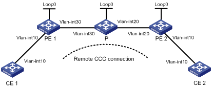
Figure 2-1 Network Diagram for caonfiguring a remote CCC conection
|
Device |
Interface |
IP address |
Device |
Interface |
IP address |
|
CE 1 |
Vlan-int10 |
100.1.1.1/24 |
P |
Loop0 |
10.0.0.2/32 |
|
PE 1 |
Loop0 |
10.0.0.1/32 |
|
Vlan-int20 |
10.2.2.2/24 |
|
|
Vlan-int30 |
10.1.1.1/24 |
|
Vlan-int30 |
10.1.1.2/24 |
|
CE 2 |
Vlan-int10 |
100.1.1.2/24 |
PE 2 |
Loop0 |
10.0.0.3/32 |
|
|
|
|
|
Vlan-int20 |
10.2.2.1/24 |
Networking and Configuration Requirements
l The CEs are connected to the PEs through VLAN interfaces.
l A remote CCC connection is created between CE 1 and CE 2.
Applicable Product Matrix
|
Product series |
Software version |
Hardware version |
|
S7500E Series Ethernet Switches |
Release 6300, |
LSQ1SRP1CB SRPU(s), or exclusively EA series LPUs |
Configuration Procedure
The main steps for configuring a remote CCC connection are:
l Create remote CCC connections on the PEs. No static LSP is required on the PEs.
l Configure two static LSPs on the P device for packets to be transferred in both directions.
1) Configure CE 1
<Sysname> system-view
[Sysname] sysname CE1
[CE1] interface vlan-interface 10
[CE1-Vlan-interface10] ip address 100.1.1.1 24
2) Configure PE 1
# Configure the LSR ID and enable MPLS globally.
<Sysname> system-view
[Sysname] sysname PE1
[PE1] interface loopback 0
[PE1-LoopBack0] ip address 10.0.0.1 32
[PE1-LoopBack0] quit
[PE1] mpls lsr-id 10.0.0.1
[PE1] mpls
[PE1-mpls] quit
# Enable MPLS L2VPN globally.
[PE1] mpls l2vpn
# Create interface VLAN-interface 10.
[PE1] interface Vlan-interface 10
[PE1-Vlan-interface10] quit
# Configure interface VLAN-interface 30 and enable MPLS.
[PE1] interface vlan-interface 30
[PE1-Vlan-interface30] ip address 10.1.1.1 24
[PE1-Vlan-interface30] mpls
[PE1-Vlan-interface30] quit
# Create a remote connection from CE 1 to CE 2, using the interface connecting CE 1 as the incoming interface and that connecting the P device as the outgoing interface, setting the incoming label to 100 and the outgoing label to 200.
[PE1] ccc ce1-ce2 interface vlan-interface 10 in-label 100 out-label 200 next-hop 10.1.1.2
3) Configure the P device
# Configure the LSR ID and enable MPLS globally.
<Sysname> system-view
[Sysname] sysname P
[P] interface loopback 0
[P-LoopBack0] ip address 10.0.0.2 32
[P-LoopBack0] quit
[P] mpls lsr-id 10.0.0.2
[P] mpls
[P-mpls] quit
# Configure interface VLAN-interface 30 and enable MPLS.
[P] interface vlan-interface 30
[P-Vlan-interface30] ip address 10.1.1.2 24
[P-Vlan-interface30] mpls
[P-Vlan-interface30] quit
# Configure interface VLAN-interface 20 and enable MPLS.
[P] interface vlan-interface 20
[P-Vlan-interface20] ip address 10.2.2.2 24
[P-Vlan-interface20] mpls
[P-Vlan-interface20] quit
# Create a static LSP for forwarding packets from PE 1 to PE 2.
[P] static-lsp transit pe1_pe2 incoming-interface vlan-interface 10 in-label 200 next-hop 10.2.2.1 out-label 201
# Create a static LSP for forwarding packets from PE 2 to PE 1.
[P] static-lsp transit pe2_pe1 incoming-interface vlan-interface 20 in-label 101 next-hop 10.1.1.1 out-label 100
4) Configure PE 2
# Configure the LSR ID and enable MPLS globally.
<Sysname> system-view
[Sysname] sysname PE2
[PE2] interface loopback 0
[PE2-LoopBack0] ip address 10.0.0.3 32
[PE2-LoopBack0] quit
[PE2] mpls lsr-id 10.0.0.3
[PE2] mpls
[PE2-mpls] quit
# Enable MPLS L2VPN globally.
[PE2] mpls l2vpn
# Configure interface VLAN-interface 10.
[PE2] interface vlan-interface 10
[PE2-Vlan-interface20] quit
# Configure interface VLAN-interface 20 and enable MPLS.
[PE2] interface vlan-interface 20
[PE2-Vlan-interface20] ip address 10.2.2.1 24
[PE2-Vlan-interface20] mpls
[PE2-Vlan-interface20] quit
# Create a remote connection from CE 2 to CE 1, using the interface connecting CE 2 as the incoming interface and that connecting the P device as the outgoing interface, setting the incoming label to 201 and the outgoing label to 101.
[PE2] ccc ce2-ce1 interface vlan-interface 10 in-label 201 out-label 101 next-hop 10.2.2.2
5) Configure CE 2
<Sysname> system-view
[Sysname] sysname CE2
[CE2] interface vlan-interface 10
[CE2-Vlan-interface10] ip address 100.1.1.2 24
6) Verify your configuration
After completing the above configurations, you can display CCC connection information on PE 1. There should be one local CCC connection established. CE 1 and CE 2 should be able to ping each other.
# Display CCC connection information on PE 1.
[PE1] display ccc
Total ccc vc : 1
Local ccc vc : 0, 0 up
Remote ccc vc : 1, 1 up
***Name : ce1-ce2
Type : remote
State : up
Intf : Vlan-interface10 (up)
In-label : 100
Out-label : 200
Nexthop : 10.1.1.2
# Ping CE 2 from CE 1.
[CE1] ping 100.1.1.2
PING 100.1.1.2: 56 data bytes, press CTRL_C to break
Reply from 100.1.1.2: bytes=56 Sequence=1 ttl=255 time=180 ms
Reply from 100.1.1.2: bytes=56 Sequence=2 ttl=255 time=60 ms
Reply from 100.1.1.2: bytes=56 Sequence=3 ttl=255 time=10 ms
Reply from 100.1.1.2: bytes=56 Sequence=4 ttl=255 time=70 ms
Reply from 100.1.1.2: bytes=56 Sequence=5 ttl=255 time=60 ms
--- 100.1.1.2 ping statistics ---
5 packet(s) transmitted
5 packet(s) received
0.00% packet loss
round-trip min/avg/max = 10/76/180 ms
Complete Configuration
l Configuration on CE 1
#
interface Vlan-interface10
ip address 100.1.1.1 255.255.255.0
l Configuration on PE 1
#
mpls lsr-id 10.0.0.1
#
mpls
#
mpls l2vpn
#
interface LoopBack0
ip address 10.0.0.1 255.255.255.255
#
interface Vlan-interface10
#
interface Vlan-interface30
ip address 10.1.1.1 255.255.255.0
mpls
#
ccc ce1-ce2 interface Vlan-interface10 in-label 100 out-label 200 nexthop 10.1.1.2
l Configuration on P
#
mpls lsr-id 10.0.0.2
#
mpls
#
interface Vlan-interface20
ip address 10.2.2.2 255.255.255.0
mpls
#
interface Vlan-interface30
ip address 10.1.1.2 255.255.255.0
mpls
#
static-lsp transit pe1_pe2 incoming-interface Vlan-interface30 in-label 200 nexthop 10.2.2.1 out-label 201
static-lsp transit pe2_pe1 incoming-interface Vlan-interface20 in-label 101 nexthop 10.1.1.1 out-label 100
l Configuration on PE 2
#
mpls lsr-id 10.0.0.3
#
mpls
#
mpls l2vpn
#
interface LoopBack0
ip address 10.0.0.3 255.255.255.255
#
interface Vlan-interface10
#
interface Vlan-interface20
ip address 10.2.2.1 255.255.255.0
mpls
#
ccc ce2-ce1 interface vlan-interface 10 in-label 201 out-label 101 next-hop 10.2.2.2
l Configuration on CE 2
#
interface Vlan-interface10
ip address 100.1.1.2 255.255.255.0
Configuration Guidelines
l You do not need to configure two LSPs for each remote CCC connection on a PE. Instead, you just need to configure an incoming label and outgoing label for a remote CCC connection. The incoming label is for the CCC connection exclusively, which therefore equals the configuration of static LSPs.
l On each P device between two PEs, you need to configure two static LSPs in opposite directions (bi-directional LSP) for transmitting data of CCC connections.
Configuring SVC MPLS L2VPN
Network Diagram

|
Device |
Interface |
IP address |
Device |
Interface |
IP address |
|
CE 1 |
Vlan-int10 |
100.1.1.1/24 |
P |
Loop0 |
192.4.4.4/32 |
|
PE 1 |
Loop0 |
192.2.2.2/32 |
|
Vlan-int30 |
10.2.2.2/24 |
|
|
Vlan-int20 |
10.1.1.1/24 |
|
Vlan-int20 |
10.1.1.2/24 |
|
CE 2 |
Vlan-int10 |
100.1.1.2/24 |
PE 2 |
Loop0 |
192.3.3.3/32 |
|
|
|
|
|
Vlan-int30 |
10.2.2.1/24 |
Figure 2-2 Network diagram for configuring SVC MPLS L2VPN
Networking and Configuration Requirements
l CEs are connected to PEs through VLAN interfaces.
l An SVC MPLS L2VPN is established between CE 1 and CE 2.
Applicable Product Matrix
|
Product series |
Software version |
Hardware version |
|
S7500E Series Ethernet Switches |
Release 6300, |
LSQ1SRP1CB SRPU(s), or exclusively EA series LPUs |
Configuration Procedure
The main steps are the following two:
l Configure MPLS basic forwarding capability on the PEs and P device. This includes configuring the LSR ID, enabling MPLS and LDP, and running IGP (OSPF in this example) between PE 1, the P device, and PE 2 to establish LSPs.
l Establish an SVC MPLS L2VPN connection. This includes enabling MPLS L2VPN on PE 1 and PE 2 and establishing an SVC connection and specifying the VC labels.
1) Configure CE 1
<Sysname> system-view
[Sysname] sysname CE1
[CE1] interface vlan-interface 10
[CE1-Vlan-interface10] ip address 100.1.1.1 24
2) Configure PE 1
# Configure the LSR ID and enable MPLS globally.
<Sysname> system-view
[Sysname] sysname PE1
[PE1] interface loopback 0
[PE1-LoopBack0] ip address 192.2.2.2 32
[PE1-LoopBack0] quit
[PE1] mpls lsr-id 192.2.2.2
[PE1] mpls
# Configure the LSP establishment triggering policy.
[PE1-mpls] lsp-trigger all
[PE1-mpls] quit
# Enable MPLS L2VPN and LDP globally.
[PE1] mpls l2vpn
[PE1] mpls ldp
[PE1-mpls-ldp] quit
# Configure the interface connected with the P device, namely VLAN-interface 20, and enable LDP on the interface.
[PE1] interface vlan-interface 20
[PE1-Vlan-interface20] ip address 10.1.1.1 24
[PE1-Vlan-interface20] mpls
[PE1-Vlan-interface20] mpls ldp
[PE1-Vlan-interface20] quit
# Configure OSPF on PE 1 for establishing LSPs.
[PE1] ospf
[PE1-ospf-1] area 0
[PE1-ospf-1-area-0.0.0.0] network 10.1.1.1 0.0.0.255
[PE1-ospf-1-area-0.0.0.0] network 192.2.2.2 0.0.0.0
[PE1-ospf-1-area-0.0.0.0] quit
[PE1-ospf-1] quit
# On the interface connecting CE 1, namely VLAN-interface 10, create an SVC MPLS L2VPN connection. The interface requires no IP address.
[PE1] interface vlan-interface 10
[PE1-Vlan-interface10] mpls static-l2vc destination 192.3.3.3 transmit-vpn-label 100 receive-vpn-label 200
[PE1-Vlan-interface10] quit
3) Configure the P device
# Configure the LSR ID and enable MPLS globally.
<Sysname> system-view
[Sysname] sysname P
[P] interface loopback 0
[P-LoopBack0] ip address 192.4.4.4 32
[P-LoopBack0] quit
[P] mpls lsr-id 192.4.4.4
[P] mpls
# Configure the LSP establishment triggering policy.
[P-mpls] lsp-trigger all
[P-mpls] quit
# Enable LDP globally.
[P] mpls ldp
[P-mpls-ldp] quit
# Configure the interface connected with PE 1, namely VLAN-interface 20, and enable LDP on the interface.
[P] interface vlan-interface 20
[P-Vlan-interface20] ip address 10.1.1.2 24
[P-Vlan-interface20] mpls
[P-Vlan-interface20] mpls ldp
[P-Vlan-interface20] quit
# Configure the interface connected with PE 2, namely VLAN-interface 30, and enable LDP on the interface.
[P] interface vlan-interface 30
[P-Vlan-interface30] link-protocol ppp
[P-Vlan-interface30] ip address 10.2.2.2 24
[P-Vlan-interface30] mpls
[P-Vlan-interface30] mpls ldp
[P-Vlan-interface30] quit
# Configure OSPF on the P device for establishing LSPs.
[P] ospf
[P-ospf-1] area 0
[P-ospf-1-area-0.0.0.0] network 10.1.1.2 0.0.0.255
[P-ospf-1-area-0.0.0.0] network 10.2.2.2 0.0.0.255
[P-ospf-1-area-0.0.0.0] network 192.4.4.4 0.0.0.0
[P-ospf-1-area-0.0.0.0] quit
[P-ospf-1] quit
4) Configure PE 2
# Configure the LSR ID and enable MPLS globally.
<Sysname> system-view
[Sysname] sysname PE2
[PE2] interface loopback 0
[PE2-LoopBack0] ip address 192.3.3.3 32
[PE2-LoopBack0] quit
[PE2] mpls lsr-id 192.3.3.3
[PE2] mpls
# Configure the LSP establishment triggering policy.
[PE2-mpls] lsp-trigger all
[PE2-mpls] quit
# Enable MPLS L2VPN and LDP globally.
[PE2] mpls l2vpn
[PE2] mpls ldp
[PE2-mpls-ldp] quit
# Configure the interface connected with the P device, namely VLAN-interface 30, and enable LDP on the interface.
[PE2] interface vlan-interface 30
[PE2-Vlan-interface30] ip address 10.2.2.1 24
[PE2-Vlan-interface30] mpls
[PE2-Vlan-interface30] mpls ldp
[PE2-Vlan-interface30] quit
# Configure OSPF on PE 2 for establishing LSPs.
[PE2] ospf
[PE2-ospf-1] area 0
[PE2-ospf-1-area-0.0.0.0] network 10.2.2.1 0.0.0.255
[PE2-ospf-1-area-0.0.0.0] network 192.3.3.3 0.0.0.0
[PE2-ospf-1-area-0.0.0.0] quit
[PE2-ospf-1] quit
# On the interface connecting CE 2, namely VLAN-interface 10, create an SVC MPLS L2VPN connection. The interface requires no IP address.
[PE2] interface vlan-interface 10
[PE2-Vlan-interface10] mpls static-l2vc destination 192.2.2.2 transmit-vpn-label 200 receive-vpn-label 100
[PE2-Vlan-interface10] quit
5) Configure CE 2
<Sysname> system-view
[Sysname] sysname CE2
[CE2] interface vlan-interface 10
[CE2-Vlan-interface10] ip address 100.1.1.2 24
6) Verify your configuration
After completing the above configurations, you can display SVC L2VPN connection information on PE 1 or PE 2. There should be one L2VPN connection established. CE 1 and CE 2 should be able to ping each other.
# Display SVC L2VPN connection information on PE 1.
[PE1] display mpls static-l2vc
total connections: 1, 1 up, 0 down
ce-intf state destination tr-label rcv-label tnl-policy
Vlan10 up 192.3.3.3 100 200 default
# Display SVC L2VPN connection information on PE 2.
[PE2] display mpls static-l2vc
total connections: 1, 1 up, 0 down
ce-intf state destination tr-label rcv-label tnl-policy
Vlan20 up 192.2.2.2 200 100 default
# Ping CE 2 from CE 1.
[CE1] ping 100.1.1.2
PING 100.1.1.2: 56 data bytes, press CTRL_C to break
Reply from 100.1.1.2: bytes=56 Sequence=1 ttl=255 time=150 ms
Reply from 100.1.1.2: bytes=56 Sequence=2 ttl=255 time=130 ms
Reply from 100.1.1.2: bytes=56 Sequence=3 ttl=255 time=130 ms
Reply from 100.1.1.2: bytes=56 Sequence=4 ttl=255 time=140 ms
Reply from 100.1.1.2: bytes=56 Sequence=5 ttl=255 time=80 ms
--- 100.1.1.2 ping statistics ---
5 packet(s) transmitted
5 packet(s) received
0.00% packet loss
round-trip min/avg/max = 80/126/150 ms
Complete Configuration
l Configuration on CE 1
interface Vlan-interface10
ip address 100.1.1.1 255.255.255.0
l Configuration on PE 1
#
mpls lsr-id 192.2.2.2
#
mpls
lsp-trigger all
#
mpls l2vpn
#
mpls ldp
#
interface LoopBack0
ip address 192.2.2.2 255.255.255.255
#
interface Vlan-interface10
mpls static-l2vc destination 192.3.3.3 transmit-vpn-label 100 receive-vpn-label 200
#
interface Vlan-interface20
ip address 10.1.1.1 255.255.255.0
mpls
mpls ldp
#
ospf 1
area 0
network 10.1.1.1 0.0.0.255
network 192.2.2.2 0.0.0.0
l Configuration on P
#
mpls lsr-id 192.4.4.4
#
mpls
lsp-trigger all
#
mpls ldp
#
interface LoopBack0
ip address 192.4.4.4 255.255.255.255
#
interface Vlan-interface20
ip address 10.1.1.2 255.255.255.0
mpls
mpls ldp
#
interface Vlan-interface30
ip address 10.2.2.2 255.255.255.0
mpls
mpls ldp
#
ospf 1
area 0
network 10.1.1.2 0.0.0.255
network 10.2.2.2 0.0.0.255
network 192.4.4.4 0.0.0.0
l Configuration on PE2
#
mpls lsr-id 192.3.3.3
#
mpls
lsp-trigger all
#
mpls l2vpn
#
mpls ldp
#
interface LoopBack0
ip address 192.3.3.3 255.255.255.255
#
interface Vlan-interface10
mpls static-l2vc destination 192.2.2.2 transmit-vpn-label 200 receive-vpn-label 100
#
interface Vlan-interface30
ip address 10.2.2.1 255.255.255.0
mpls
mpls ldp
#
ospf 1
area 0
network 10.2.2.1 0.0.0.255
network 192.3.3.3 0.0.0.0
l Configuration on CE2
#
interface Vlan-interface10
ip address 100.1.1.2 255.255.255.0
Configuration Guidelines
None
Configuring Martini MPLS L2VPN
Network Diagram
|
Device |
Interface |
IP address |
Device |
Interface |
IP address |
|
CE 1 |
Vlan-int10 |
100.1.1.1/24 |
P |
Loop0 |
192.4.4.4/32 |
|
PE 1 |
Loop0 |
192.2.2.2/32 |
|
Vlan-int20 |
10.1.1.2/24 |
|
|
Vlan-int20 |
10.1.1.1/24 |
|
Vlan-int30 |
10.2.2.2/24 |
|
CE 2 |
Vlan-int10 |
100.1.1.2/24 |
PE 2 |
Loop0 |
192.3.3.3/32 |
|
|
|
|
|
Vlan-int30 |
10.2.2.1/24 |
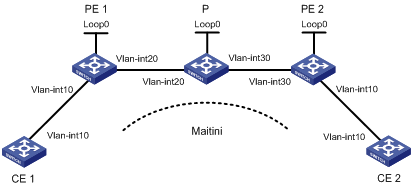
Figure 2-3 Network diagram for configuring Martini MPLS L2VPN
Networking and Configuration Requirements
l CEs are connected to PEs through VLAN interfaces.
l A Martini MPLS L2VPN is established between CE 1 and CE 2.
Applicable Product Matrix
|
Product series |
Software version |
Hardware version |
|
S7500E Series Ethernet Switches |
Release 6300, |
LSQ1SRP1CB SRPU(s), or exclusively EA series LPUs |
Configuration Procedure
1) Configure CE 1
<Sysname> system-view
[Sysname] sysname CE1
[CE1] interface vlan-interface 10
[CE1-Vlan-interface10] ip address 100.1.1.1 24
2) Configure PE 1
# Configure the LSR ID and enable MPLS globally.
<Sysname> system-view
[Sysname] sysname PE1
[PE1] interface loopback 0
[PE1-LoopBack0] ip address 192.2.2.2 32
[PE1-LoopBack0] quit
[PE1] mpls lsr-id 192.2.2.2
[PE1] mpls
# Configure the LSP establishment triggering policy.
[PE1-mpls] lsp-trigger all
[PE1-mpls] quit
# Enable MPLS L2VPN and LDP globally.
[PE1] mpls l2vpn
[PE1] mpls ldp
[PE1-mpls-ldp] quit
# Establish a remote session between PE 1 and PE 2.
[PE1] mpls ldp remote-peer 1
[PE1-mpls-ldp-remote-1] remote-ip 192.3.3.3
[PE1-mpls-ldp-remote-1] quit
# Configure the interface connected with the P device, namely VLAN-interface 20, and enable LDP on the interface.
[PE1] interface vlan-interface 20
[PE1-Vlan-interface20] ip address 10.1.1.1 24
[PE1-Vlan-interface20] mpls
[PE1-Vlan-interface20] mpls ldp
[PE1-Vlan-interface20] quit
# Configure OSPF on PE 1 for establishing LSPs.
[PE1] ospf
[PE1-ospf-1] area 0
[PE1-ospf-1-area-0.0.0.0] network 10.1.1.1 0.0.0.255
[PE1-ospf-1-area-0.0.0.0] network 192.2.2.2 0.0.0.0
[PE1-ospf-1-area-0.0.0.0] quit
[PE1-ospf-1] quit
# On the interface connecting CE 1, namely VLAN-interface 10, create a Martini MPLS L2VPN connection. The interface requires no IP address.
[PE1] interface vlan-interface 10
[PE1-Vlan-interface10] mpls l2vc 192.3.3.3 101
[PE1-Vlan-interface10] quit
3) Configure the P device
# Configure the LSR ID and enable MPLS globally.
<Sysname> system-view
[Sysname] sysname P
[P] interface loopback 0
[P-LoopBack0] ip address 192.4.4.4 32
[P-LoopBack0] quit
[P] mpls lsr-id 192.4.4.4
[P] mpls
# Configure the LSP establishment triggering policy.
[P-mpls] lsp-trigger all
[P-mpls] quit
# Enable LDP globally.
[P] mpls ldp
[P-mpls-ldp] quit
# Configure the interface connected with PE 1, namely VLAN-interface 20, and enable LDP on the interface.
[P] interface vlan-interface 20
[P-Vlan-interface20] ip address 10.1.1.2 24
[P-Vlan-interface20] mpls
[P-Vlan-interface20] mpls ldp
[P-Vlan-interface20] quit
# Configure the interface connected with PE 2, namely VLAN-interface 30, and enable LDP on the interface.
[P] interface vlan-interface 30
[P-Vlan-interface30] ip address 10.2.2.2 24
[P-Vlan-interface30] mpls
[P-Vlan-interface30] mpls ldp
[P-Vlan-interface30] quit
# Configure OSPF on the P device for establishing LSPs.
[P] ospf
[P-ospf-1] area 0
[P-ospf-1-area-0.0.0.0] network 10.1.1.2 0.0.0.255
[P-ospf-1-area-0.0.0.0] network 10.2.2.2 0.0.0.255
[P-ospf-1-area-0.0.0.0] network 192.4.4.4 0.0.0.0
[P-ospf-1-area-0.0.0.0] quit
[P-ospf-1] quit
4) Configure PE 2
# Configure the LSR ID and enable MPLS globally.
<Sysname> system-view
[Sysname] sysname PE2
[PE2] interface loopback 0
[PE2-LoopBack0] ip address 192.3.3.3 32
[PE2-LoopBack0] quit
[PE2] mpls lsr-id 192.3.3.3
[PE2] mpls
# Configure the LSP establishment triggering policy.
[PE2-mpls] lsp-trigger all
[PE2-mpls] quit
# Enable MPLS L2VPN and LDP globally.
[PE2] mpls l2vpn
[PE2] mpls ldp
[PE2-mpls-ldp] quit
# Configure an LDP remote session between PE 2 and PE 1.
[PE2] mpls ldp remote-peer 2
[PE2-mpls-ldp-remote-2] remote-ip 192.2.2.2
[PE2-mpls-ldp-remote-2] quit
# Configure the interface connected with the P device, namely VLAN-interface 30, and enable LDP on the interface.
[PE2] interface vlan-interface 30
[PE2-Vlan-interface30] ip address 10.2.2.1 24
[PE2-Vlan-interface30] mpls
[PE2-Vlan-interface30] mpls ldp
[PE2-Vlan-interface30] quit
# Configure OSPF on PE 2 for establishing LSPs.
[PE2] ospf
[PE2-ospf-1] area 0
[PE2-ospf-1-area-0.0.0.0] network 192.3.3.3 0.0.0.0
[PE2-ospf-1-area-0.0.0.0] network 10.2.2.0 0.0.0.255
[PE2-ospf-1-area-0.0.0.0] quit
[PE2-ospf-1] quit
# On the interface connecting CE 2, namely VLAN-interface 10, create a L2VPN connection. The interface requires no IP address.
[PE2] interface vlan-interface 10
[PE2-Vlan-interface10] mpls l2vc 192.2.2.2 101
[PE2-Vlan-interface10] quit
5) Configure CE 2
<Sysname> system-view
[Sysname] sysname CE2
[CE2] interface vlan-interface 10
[CE2-Vlan-interface10] ip address 100.1.1.2 24
6) Verify your configuration
After completing the above configurations, you can display L2VPN connection information on PE 1 or PE 2. There should be one L2VC established. CE 1 and CE 2 should be able to ping each other.
# Display L2VPN connection information on PE 1.
[PE1] display mpls l2vc
total ldp vc : 1 1 up 0 down
Transport Client VC Local Remote Tunnel
VC ID Intf State VC Label VC Label Policy
101 Vlan10 up 8193 8192 default
# Display L2VPN connection information on PE 2.
[PE2] display mpls l2vc
total ldp vc : 1 1 up 0 down
Transport Client VC Local Remote Tunnel
VC ID Intf State VC Label VC Label Policy
101 Vlan10 up 8192 8193 default
# Ping CE 2 from CE 1.
[CE1] ping 100.1.1.2
PING 100.1.1.2: 56 data bytes, press CTRL_C to break
Reply from 100.1.1.2: bytes=56 Sequence=1 ttl=255 time=30 ms
Reply from 100.1.1.2: bytes=56 Sequence=2 ttl=255 time=60 ms
Reply from 100.1.1.2: bytes=56 Sequence=3 ttl=255 time=50 ms
Reply from 100.1.1.2: bytes=56 Sequence=4 ttl=255 time=40 ms
Reply from 100.1.1.2: bytes=56 Sequence=5 ttl=255 time=70 ms
--- 100.1.1.2 ping statistics ---
5 packet(s) transmitted
5 packet(s) received
0.00% packet loss
round-trip min/avg/max = 30/50/70 ms
Complete Configuration
l Configuration on CE 1
#
interface Vlan-interface10
ip address 100.1.1.1 255.255.255.0
l Configuration on PE 1
#
mpls lsr-id 192.2.2.2
#
mpls
lsp-trigger all
#
mpls l2vpn
#
mpls ldp
#
mpls ldp remote-peer 1
remote-ip 192.3.3.3
#
interface LoopBack0
ip address 192.2.2.2 255.255.255.255
#
interface Vlan-interface10
mpls l2vc 192.3.3.3 101
#
interface Vlan-interface20
ip address 10.1.1.1 255.255.255.0
mpls
mpls ldp
#
ospf 1
area 0
network 10.1.1.1 0.0.0.255
network 192.2.2.2 0.0.0.0
l Configuration on P
#
mpls lsr-id 192.4.4.4
#
mpls
lsp-trigger all
#
mpls ldp
#
interface LoopBack0
ip address 192.4.4.4 255.255.255.255
#
interface Vlan-interface20
ip address 10.1.1.2 255.255.255.0
mpls
mpls ldp
#
interface Vlan-interface30
ip address 10.2.2.2 255.255.255.0
mpls
mpls ldp
#
ospf 1
area 0
network 10.1.1.2 0.0.0.255
network 10.2.2.2 0.0.0.255
network 192.4.4.4 0.0.0.0
l Configuration on PE 2
#
mpls lsr-id 192.3.3.3
#
mpls
lsp-trigger all
#
mpls l2vpn
#
mpls ldp
#
mpls ldp remote-peer 2
remote-ip 192.2.2.2
#
interface LoopBack0
ip address 192.3.3.3 255.255.255.255
#
interface Vlan-interface10
mpls l2vc 192.2.2.2 101
#
interface Vlan-interface30
ip address 10.2.2.1 255.255.255.0
mpls
mpls ldp
#
ospf 1
area 0
network 10.2.2.1 0.0.0.255
network 192.3.3.3 0.0.0.0
l Configuration on CE 2
#
interface Vlan-interface10
ip address 100.1.1.2 255.255.255.0
Configuration Guidelines
None
Configuring Kompella MPLS L2VPN
Network Diagram
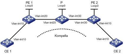
Figure 2-4 Network diagram for configuring Kompella MPLS L2VPN
|
Device |
Interface |
IP address |
Device |
Interface |
IP address |
|
CE 1 |
Vlan-int10 |
100.1.1.1/24 |
P |
Loop0 |
3.3.3.3/32 |
|
PE 1 |
Loop0 |
2.2.2.2/32 |
|
Vlan-int20 |
10.1.1.2/24 |
|
|
Vlan-int20 |
10.1.1.1/24 |
|
Vlan-int30 |
10.2.2.2/24 |
|
CE 2 |
Vlan-int10 |
100.1.1.2/24 |
PE 2 |
Loop0 |
4.4.4.4/32 |
|
|
|
|
|
Vlan-int30 |
10.2.2.1/24 |
Networking and Configuration Requirements
l CEs are connected to PEs through VLAN interfaces.
l A Kompella MPLS L2VPN is established between CE 1 and CE 2.
Applicable Product Matrix
|
Product series |
Software version |
Hardware version |
|
S7500E Series Ethernet Switches |
Release 6300, |
LSQ1SRP1CB SRPU(s), or exclusively EA series LPUs |
Configuration Procedure
1) Configure IGP on the MPLS backbone
This example uses OSPF. The detailed configuration steps are omitted.
After configuration, issuing the display ip routing-table command on each LSR, you should see that it has learned the routes to the LSR IDs of the other LSRs. Issuing the display ospf peer command, you should see that OSPF adjacencies have been established and reached the state of Full.
2) Configure MPLS basic capability and LDP to establish LDP LSPs
The detailed configuration steps are omitted.
After configuration, you can issue the display mpls ldp session and display mpls ldp peer commands to view the LDP sessions and peer relationship established, or the display mpls lsp command to view the LSPs established.
3) Configure BGP L2VPN capability
# Configure PE 1.
<Sysname> system-view
[Sysname] sysname PE1
[PE1] mpls l2vpn
[PE1] bgp 100
[PE1-bgp] peer 4.4.4.4 as-number 100
[PE1-bgp] peer 4.4.4.4 connect-interface loopback 0
[PE1-bgp] l2vpn-family
[PE1-bgp-af-l2vpn] policy vpn-target
[PE1-bgp-af-l2vpn] peer 4.4.4.4 enable
[PE1-bgp-af-l2vpn] quit
[PE1-bgp] quit
# Configure PE 2.
<Sysname> system-view
[Sysname] sysname PE2
[PE2] mpls l2vpn
[PE2] bgp 100
[PE2-bgp] peer 2.2.2.2 as-number 100
[PE2-bgp] peer 2.2.2.2 connect-interface loopback 0
[PE2-bgp] l2vpn-family
[PE2-bgp-af-l2vpn] policy vpn-target
[PE2-bgp-af-l2vpn] peer 2.2.2.2 enable
[PE2-bgp-af-l2vpn] quit
[PE2-bgp] quit
After completing the above configurations, you can issue the display bgp l2vpn peer command on PE 1 and PE 2 to view the peer relationship established between the PEs. The status should be Established. The following takes PE 1 as an example:
[PE1] display bgp l2vpn peer
BGP local router ID : 2.2.2.2
Local AS number : 100
Total number of peers : 1 Peers in established state : 1
Peer V AS MsgRcvd MsgSent OutQ PrefRcv Up/Down State
4.4.4.4 4 100 2 5 0 0 00:01:07 Established
4) Configure the L2VPN and the CE connection
# Configure PE 1. The configurations of the VLAN interfaces are similar to those for Martini MPLS L2VPN and are omitted.
[PE1] mpls l2vpn vpn1 encapsulation vlan
[PE1-mpls-l2vpn-vpn1] route-distinguisher 100:1
[PE1-mpls-l2vpn-vpn1] vpn-target 1:1
[PE1-mpls-l2vpn-vpn1] ce ce1 id 1 range 10
[PE1-mpls-l2vpn-ce-vpn1-ce1] connection ce-offset 2 interface vlan-interface 10
[PE1-mpls-l2vpn-ce-vpn1-ce1] quit
[PE1-mpls-l2vpn-vpn1] quit
# Configure PE 2.
[PE2] mpls l2vpn vpn1 encapsulation vlan
[PE2-mpls-l2vpn-vpn1] route-distinguisher 100:1
[PE2-mpls-l2vpn-vpn1] vpn-target 1:1
[PE2-mpls-l2vpn-vpn1] ce ce2 id 2 range 10
[PE2-mpls-l2vpn-ce-vpn1-ce2] connection ce-offset 1 interface vlan-interface 10
[PE2-mpls-l2vpn-ce-vpn1-ce2] quit
[PE2-mpls-l2vpn-vpn1] quit
5) Verify your configuration
After completing the above configurations, you can issue the display mpls l2vpn connection command on the PEs. You should see that an L2VPN connection is established between the PEs and the connection is up. CE 1 and CE 2 should be able to ping each other. The following takes PE 1 as an example:
# Display the MPLS L2VPN connection information on PE 1.
[PE1] display mpls l2vpn connection
1 total connections,
connections: 1 up, 0 down, 0 local, 1 remote, 0 unknown
VPN name: vpn1,
1 total connections,
connections: 1 up, 0 down, 0 local, 1 remote, 0 unknown
CE name: ce1, id: 1,
Rid type status peer-id route-distinguisher intf
2 rmt up 4.4.4.4 100:1 Vlan10
# Ping CE 2 from CE 1.
[CE1] ping 100.1.1.2
PING 100.1.1.2: 56 data bytes, press CTRL_C to break
Reply from 100.1.1.2: bytes=56 Sequence=1 ttl=255 time=90 ms
Reply from 100.1.1.2: bytes=56 Sequence=2 ttl=255 time=77 ms
Reply from 100.1.1.2: bytes=56 Sequence=3 ttl=255 time=34 ms
Reply from 100.1.1.2: bytes=56 Sequence=4 ttl=255 time=46 ms
Reply from 100.1.1.2: bytes=56 Sequence=5 ttl=255 time=94 ms
--- 100.1.1.2 ping statistics ---
5 packet(s) transmitted
5 packet(s) received
0.00% packet loss
round-trip min/avg/max = 34/68/94 ms
Complete Configuration
l Configuration on CE 1
#
interface Vlan-interface10
ip address 100.1.1.1 255.255.255.0
l Configuration on PE 1
#
mpls lsr-id 2.2.2.2
#
mpls
lsp-trigger all
#
mpls l2vpn
#
mpls ldp
#
interface LoopBack0
ip address 2.2.2.2 255.255.255.255
#
interface Vlan-interface10
#
interface Vlan-interface20
ip address 10.1.1.1 255.255.255.0
mpls
mpls ldp
#
ospf 1
area 0
network 10.1.1.1 0.0.0.255
network 2.2.2.2 0.0.0.0
#
bgp 100
undo synchronization
peer 4.4.4.4 as-number 100
peer 4.4.4.4 connect-interface LoopBack0
#
l2vpn-family
peer 4.4.4.4 enable
#
mpls l2vpn vpn1 encapsulation vlan
route-distinguisher 100:1
vpn-target 1:1 import-extcommunity
vpn-target 1:1 export-extcommunity
ce ce1 id 1 range 10 default-offset 0
connection ce-offset 2 interface Vlan-interface10
l Configuration on P
#
mpls lsr-id 3.3.3.3
#
mpls
lsp-trigger all
#
mpls ldp
#
interface LoopBack0
ip address 3.3.3.3 255.255.255.255
#
interface Vlan-interface20
ip address 10.1.1.2 255.255.255.0
mpls
mpls ldp
#
interface Vlan-interface30
ip address 10.2.2.2 255.255.255.0
mpls
mpls ldp
#
ospf 1
area 0
network 10.1.1.2 0.0.0.255
network 10.2.2.2 0.0.0.255
network 3.3.3.3 0.0.0.0
l Configuration on PE 2
#
mpls lsr-id 4.4.4.4
#
mpls
lsp-trigger all
#
mpls l2vpn
#
mpls ldp
#
interface LoopBack0
ip address 4.4.4.4 255.255.255.255
#
interface Vlan-interface10
#
interface Vlan-interface30
ip address 10.2.2.1 255.255.255.0
mpls
mpls ldp
#
ospf 1
area 0
network 10.2.2.1 0.0.0.255
network 4.4.4.4 0.0.0.0
#
bgp 100
undo synchronization
peer 2.2.2.2 as-number 100
peer 2.2.2.2 connect-interface LoopBack0
#
l2vpn-family
peer 2.2.2.2 enable
#
mpls l2vpn vpn1 encapsulation vlan
route-distinguisher 100:1
vpn-target 1:1 import-extcommunity
vpn-target 1:1 export-extcommunity
ce ce2 id 2 range 10 default-offset 0
connection ce-offset 1 interface Vlan-interface10
l Configuration on CE 2
#
interface Vlan-interface10
ip address 100.1.1.2 255.255.255.0
Configuration Guidelines
l To configure Kompella MPLS L2VPN, on a PE, you need to configure an L2VPN instance respectively for each VPN that a directly connected CE belongs to. When configuring an L2VPN, you need to specify the same encapsulation type as that on the CE-side interface.
l The functions of the VPN targets and Route Distinguishers (RDs) configured above in MPLS-L2VPN view are the same as those configured in MPLS L3VPN. For a Kompella L2VPN, you must configure an RD. You cannot change an RD directly; you can only delete the VPN instance, re-create the VPN instance, and then configure a new RD.
Configuring MPLS L3VPNs
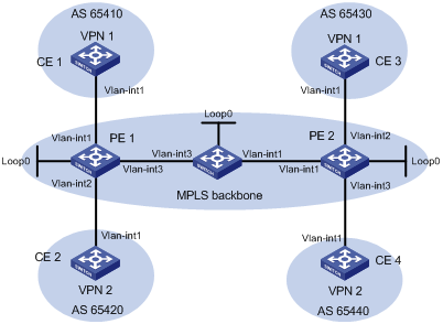
Network Diagram
Figure 3-1 Configure MPLS L3VPNs
|
Interface |
IP address |
Device |
Interface |
IP address |
|
|
CE 1 |
Vlan-int1 |
10.1.1.1/24 |
P |
Loop0 |
2.2.2.9/32 |
|
PE 1 |
Loop0 |
1.1.1.9/32 |
|
Vlan-int1 |
172.2.1.1/24 |
|
|
Vlan-int1 |
10.1.1.2/24 |
|
Vlan-int3 |
172.1.1.2/24 |
|
|
Vlan-int3 |
172.1.1.1/24 |
PE 2 |
Loop0 |
3.3.3.9/32 |
|
|
Vlan-int2 |
10.2.1.2/24 |
|
Vlan-int1 |
172.2.1.2/24 |
|
CE 2 |
Vlan-int1 |
10.2.1.1/24 |
|
Vlan-int2 |
10.3.1.2/24 |
|
CE 3 |
Vlan-int1 |
10.3.1.1/24 |
|
Vlan-int3 |
10.4.1.2/24 |
|
CE 4 |
Vlan-int1 |
10.4.1.1/24 |
|
|
|
Networking and Configuration Requirements
l CE 1 and CE 3 belong to VPN 1, while CE 2 and CE 4 belong to VPN 2.
l VPN 1 uses VPN target attributes 111:1, while VPN 2 uses VPN target attributes 222:2. Users of different VPNs cannot access each other.
l PEs and the P device support MPLS.
Applicable Product Matrix
|
Product series |
Software version |
Hardware version |
|
S7500E Series Ethernet Switches |
Release 6300, |
LSQ1SRP1CB SRPU(s), or exclusively EA series LPUs |
Configuration Procedure
1) Configure IGP on the MPLS backbone, enabling the PEs and the P device to communicate
# Configure PE 1.
<PE1> system-view
[PE1] interface loopback 0
[PE1-LoopBack0] ip address 1.1.1.9 32
[PE1-LoopBack0] quit
[PE1] interface vlan-interface 3
[PE1-Vlan-interface3] ip address 172.1.1.1 24
[PE1-Vlan-interface3] quit
[PE1] ospf
[PE1-ospf-1] area 0
[PE1-ospf-1-area-0.0.0.0] network 172.1.1.0 0.0.0.255
[PE1-ospf-1-area-0.0.0.0] network 1.1.1.9 0.0.0.0
[PE1-ospf-1-area-0.0.0.0] quit
[PE1-ospf-1] quit
# Configure the P device.
<P> system-view
[P] interface loopback 0
[P-LoopBack0] ip address 2.2.2.9 32
[P-LoopBack0] quit
[P] interface vlan-interface 3
[P-Vlan-interface3] ip address 172.1.1.2 24
[P-Vlan-interface3] quit
[P] interface vlan-interface 1
[P-Vlan-interface1] ip address 172.2.1.1 24
[P-Vlan-interface1] quit
[P] ospf
[P-ospf-1] area 0
[P-ospf-1-area-0.0.0.0] network 172.1.1.0 0.0.0.255
[P-ospf-1-area-0.0.0.0] network 172.2.1.0 0.0.0.255
[P-ospf-1-area-0.0.0.0] network 2.2.2.9 0.0.0.0
[P-ospf-1-area-0.0.0.0] quit
[P-ospf-1] quit
# Configure PE 2.
<PE2> system-view
[PE2] interface loopback 0
[PE2-LoopBack0] ip address 3.3.3.9 32
[PE2-LoopBack0] quit
[PE2] interface vlan-interface 1
[PE2-Vlan-interface1] ip address 172.2.1.2 24
[PE2-Vlan-interface1] quit
[PE2] ospf
[PE2-ospf-1] area 0
[PE2-ospf-1-area-0.0.0.0] network 172.2.1.0 0.0.0.255
[PE2-ospf-1-area-0.0.0.0] network 3.3.3.9 0.0.0.0
[PE2-ospf-1-area-0.0.0.0] quit
[PE2-ospf-1] quit
After you complete the above configurations, OSPF adjacency should be established between PE 1, P, and PE 2. Issuing the display ospf peer command, you can see that the adjacency status is Full. Issuing the display ip routing-table command, you can see that the PEs have learned the loopback route of each other. The following takes PE 1 as an example:
[PE1] display ip routing-table
Routing Tables: Public
Destinations : 9 Routes : 9
Destination/Mask Proto Pre Cost NextHop Interface
1.1.1.9/32 Direct 0 0 127.0.0.1 InLoop0
2.2.2.9/32 OSPF 10 1 172.1.1.2 Vlan3
3.3.3.9/32 OSPF 10 2 172.1.1.2 Vlan3
127.0.0.0/8 Direct 0 0 127.0.0.1 InLoop0
127.0.0.1/32 Direct 0 0 127.0.0.1 InLoop0
172.1.1.0/24 Direct 0 0 172.1.1.1 Vlan3
172.1.1.1/32 Direct 0 0 127.0.0.1 InLoop0
172.1.1.2/32 Direct 0 0 172.1.1.2 Vlan3
172.2.1.0/24 OSPF 10 1 172.1.1.2 Vlan3
[PE1] display ospf peer verbose
OSPF Process 1 with Router ID 1.1.1.9
Neighbors
Area 0.0.0.0 interface 172.1.1.1(Vlan-interface3)'s neighbors
Router ID: 172.1.1.2 Address: 172.1.1.2 GR State: Normal
State: Full Mode:Nbr is Master Priority: 1
DR: None BDR: None MTU: 1500
Dead timer due in 38 sec
Neighbor is up for 00:02:44
Authentication Sequence: [ 0 ]
Neighbor state change count: 5
2) Configure MPLS basic capability and MPLS LDP on the MPLS backbone to establish LDP LSPs
# Configure PE 1.
[PE1] mpls lsr-id 1.1.1.9
[PE1] mpls
[PE1-mpls] quit
[PE1] mpls ldp
[PE1-mpls-ldp] quit
[PE1] interface vlan-interface 3
[PE1-Vlan-interface3] mpls
[PE1-Vlan-interface3] mpls ldp
[PE1-Vlan-interface3] quit
# Configure the P device.
[P] mpls lsr-id 2.2.2.9
[P] mpls
[P-mpls] quit
[P] mpls ldp
[P-mpls-ldp] quit
[P] interface vlan-interface 3
[P-Vlan-interface3] mpls
[P-Vlan-interface3] mpls ldp
[P-Vlan-interface3] quit
[P] interface vlan-interface 1
[P-Vlan-interface1] mpls
[P-Vlan0interface1] mpls ldp
[P-Vlan-interface1] quit
# Configure PE 2.
[PE2] mpls lsr-id 3.3.3.9
[PE2] mpls
[PE2-mpls] quit
[PE2] mpls ldp
[PE2-mpls-ldp] quit
[PE2] interface vlan-interface 1
[PE2-Vlan-interface1] mpls
[PE2-Vlan-interface1] mpls ldp
[PE2-Vlan-interface1] quit
After you complete the above configurations, LDP sessions should be established between PE 1, P, and PE 2. Issuing the display mpls ldp session command, you can see that the Session State field has a value of Operational. Issuing the display mpls ldp lsp command, you can see that the LSPs established by LDP. The following takes PE 1 as an example:
[PE1] display mpls ldp session
LDP Session(s) in Public Network
----------------------------------------------------------------
Peer-ID Status LAM SsnRole FT MD5 KA-Sent/Rcv
---------------------------------------------------------------
2.2.2.9:0 Operational DU Passive Off Off 5/5
---------------------------------------------------------------
LAM : Label Advertisement Mode FT : Fault Tolerance
[PE1] display mpls ldp lsp
LDP LSP Information
------------------------------------------------------------------
SN DestAddress/Mask In/OutLabel Next-Hop In/Out-Interface
------------------------------------------------------------------
1 1.1.1.9/32 3/NULL 127.0.0.1 Vlan-interface3/InLoop0
2 2.2.2.9/32 NULL/3 172.1.1.2 -------/Vlan-interface3
3 3.3.3.9/32 NULL/1024 172.1.1.2 -------/Vlan-interface3
------------------------------------------------------------------
A '*' before an LSP means the LSP is not established
A '*' before a Label means the USCB or DSCB is stale
3) Configure VPN instances on PEs to allow CEs to access
# Configure PE 1.
[PE1] ip vpn-instance vpn1
[PE1-vpn-instance-vpn1] route-distinguisher 100:1
[PE1-vpn-instance-vpn1] vpn-target 111:1
[PE1-vpn-instance-vpn1] quit
[PE1] ip vpn-instance vpn2
[PE1-vpn-instance-vpn2] route-distinguisher 100:2
[PE1-vpn-instance-vpn2] vpn-target 222:2
[PE1-vpn-instance-vpn2] quit
[PE1] interface vlan-interface 1
[PE1-Vlan-interface1] ip binding vpn-instance vpn1
[PE1-Vlan-interface1] ip address 10.1.1.2 24
[PE1-Vlan-interface1] quit
[PE1] interface vlan-interface 2
[PE1-Vlan-interface2] ip binding vpn-instance vpn2
[PE1-Vlan-interface2] ip address 10.2.1.2 24
[PE1-Vlan-interface2] quit
# Configure PE 2.
[PE2] ip vpn-instance vpn1
[PE2-vpn-instance-vpn1] route-distinguisher 200:1
[PE2-vpn-instance-vpn1] vpn-target 111:1
[PE2-vpn-instance-vpn1] quit
[PE2] ip vpn-instance vpn2
[PE2-vpn-instance-vpn2] route-distinguisher 200:2
[PE2-vpn-instance-vpn2] vpn-target 222:2
[PE2-vpn-instance-vpn2] quit
[PE2] interface vlan-interface 2
[PE2-Vlan-interface2] ip binding vpn-instance vpn1
[PE2-Vlan-interface2] ip address 10.3.1.2 24
[PE2-Vlan-interface2] quit
[PE2] interface vlan-interface 3
[PE2-Vlan-interface3] ip binding vpn-instance vpn2
[PE2-Vlan-interface3] ip address 10.4.1.2 24
[PE2-Vlan-interface3] quit
# Configure IP addresses for the CEs as required in Figure 3-1. The detailed configuration steps are omitted.
After completing the above configurations, you can issue the display ip vpn-instance command on the PEs to view the configuration of the VPN instance. The PEs should be capable of pinging their respective CEs. The following takes PE 1 and CE 1 as an example:
[PE1] display ip vpn-instance
Total VPN-Instances configured : 2
VPN-Instance Name RD Create Time
vpn1 100:1 2006/08/13 09:32:45
vpn2 100:2 2006/08/13 09:42:59
[PE1] ping -vpn-instance vpn1 10.1.1.1
PING 10.1.1.1: 56 data bytes, press CTRL_C to break
Reply from 10.1.1.1: bytes=56 Sequence=1 ttl=255 time=56 ms
Reply from 10.1.1.1: bytes=56 Sequence=2 ttl=255 time=4 ms
Reply from 10.1.1.1: bytes=56 Sequence=3 ttl=255 time=4 ms
Reply from 10.1.1.1: bytes=56 Sequence=4 ttl=255 time=52 ms
Reply from 10.1.1.1: bytes=56 Sequence=5 ttl=255 time=3 ms
--- 10.1.1.1 ping statistics ---
5 packet(s) transmitted
5 packet(s) received
0.00% packet loss
round-trip min/avg/max = 3/23/56 ms
4) Establish EBGP peer relationship between PEs and CEs to allow VPN routes to be injected
# Configure CE 1.
<CE1> system-view
[CE1] bgp 65410
[CE1-bgp] peer 10.1.1.2 as-number 100
[CE1-bgp] import-route direct
[CE1-bgp] quit
![]()
The configurations for the other three CEs are similar to the above. The detailed configuration steps are omitted.
# Configure PE 1.
[PE1] bgp 100
[PE1-bgp] ipv4-family vpn-instance vpn1
[PE1-bgp-vpn1] peer 10.1.1.1 as-number 65410
[PE1-bgp-vpn1] import-route direct
[PE1-bgp-vpn1] quit
[PE1-bgp] ipv4-family vpn-instance vpn2
[PE1-bgp-vpn2] peer 10.2.1.1 as-number 65420
[PE1-bgp-vpn2] import-route direct
[PE1-bgp-vpn2] quit
[PE1-bgp] quit
![]()
The configurations for PE 2 are similar to those for PE 1. The detailed configuration steps are omitted.
After completing the above configuration, if you issue the display bgp vpnv4 vpn-instance peer command on the PEs, you should see that BGP peer relationship has been established between PE and CE, and has reached the state of Established. The following takes PE 1 and CE 1 as an example:
[PE1] display bgp vpnv4 vpn-instance vpn1 peer
BGP local router ID : 1.1.1.9
Local AS number : 100
Total number of peers : 1 Peers in established state : 1
Peer V AS MsgRcvd MsgSent OutQ PrefRcv Up/Down State
10.1.1.1 4 65410 11 9 0 1 00:06:37 Established
5) Configure MP-IBGP peers between PEs
# Configure PE 1.
[PE1] bgp 100
[PE1-bgp] peer 3.3.3.9 as-number 100
[PE1-bgp] peer 3.3.3.9 connect-interface loopback 0
[PE1-bgp] ipv4-family vpnv4
[PE1-bgp-af-vpnv4] peer 3.3.3.9 enable
[PE1-bgp-af-vpnv4] quit
[PE1-bgp] quit
# Configure PE 2.
[PE2] bgp 100
[PE2-bgp] peer 1.1.1.9 as-number 100
[PE2-bgp] peer 1.1.1.9 connect-interface loopback 0
[PE2-bgp] ipv4-family vpnv4
[PE2-bgp-af-vpnv4] peer 1.1.1.9 enable
[PE2-bgp-af-vpnv4] quit
[PE2-bgp] quit
After completing the above configuration, if you issue the display bgp peer command or the display bgp vpnv4 all peer command on the PEs, you should see that BGP peer relationship has been established between the PEs, and has reached the state of Established.
[PE1] display bgp peer
BGP local router ID : 1.1.1.9
Local AS number : 100
Total number of peers : 1 Peers in established state : 1
Peer V AS MsgRcvd MsgSent OutQ PrefRcv Up/Down State
3.3.3.9 4 100 2 6 0 0 00:00:12 Established
6) Verify your configurations
Issuing the display ip routing-table vpn-instance command on the PEs, you should see the routes to the CEs. The following takes PE 1 as an example:
[PE1] display ip routing-table vpn-instance vpn1
Routing Tables: vpn1
Destinations : 3 Routes : 3
Destination/Mask Proto Pre Cost NextHop Interface
10.1.1.0/24 Direct 0 0 10.1.1.2 Vlan1
10.1.1.2/32 Direct 0 0 127.0.0.1 InLoop0
10.3.1.0/24 BGP 255 0 3.3.3.9 NULL0
[PE1] display ip routing-table vpn-instance vpn2
Routing Tables: vpn2
Destinations : 3 Routes : 3
Destination/Mask Proto Pre Cost NextHop Interface
10.2.1.0/24 Direct 0 0 10.2.1.2 Vlan2
10.2.1.2/32 Direct 0 0 127.0.0.1 InLoop0
10.4.1.0/24 BGP 255 0 3.3.3.9 NULL0
CEs of the same VPN should be capable of pinging each other, whereas those of different VPNs should not. For example, CE 1 should be capable of pinging CE 3 (10.3.1.1), but should not be capable of pinging CE 4 (10.4.1.1):
[CE1] ping 10.3.1.1
PING 10.3.1.1: 56 data bytes, press CTRL_C to break
Reply from 10.3.1.1: bytes=56 Sequence=1 ttl=253 time=72 ms
Reply from 10.3.1.1: bytes=56 Sequence=2 ttl=253 time=34 ms
Reply from 10.3.1.1: bytes=56 Sequence=3 ttl=253 time=50 ms
Reply from 10.3.1.1: bytes=56 Sequence=4 ttl=253 time=50 ms
Reply from 10.3.1.1: bytes=56 Sequence=5 ttl=253 time=34 ms
--- 10.3.1.1 ping statistics ---
5 packet(s) transmitted
5 packet(s) received
0.00% packet loss
round-trip min/avg/max = 34/48/72 ms
[CE1] ping 10.4.1.1
PING 10.4.1.1: 56 data bytes, press CTRL_C to break
Request time out
Request time out
Request time out
Request time out
Request time out
--- 10.4.1.1 ping statistics ---
5 packet(s) transmitted
0 packet(s) received
100.00% packet loss
Complete Configuration
l Configuration on CE 1
#
interface Vlan-interface1
ip address 10.1.1.1 255.255.255.0
#
bgp 65410
peer 10.1.1.2 as-number 100
import-route direct
l Configuration on CE 2
#
interface Vlan-interface1
ip address 10.2.1.1 255.255.255.0
#
bgp 65420
peer 10.2.1.2 as-number 100
import-route direct
l Configuration on PE 1
#
mpls lsr-id 1.1.1.9
#
ip vpn-instance vpn1
route-distinguisher 100:1
vpn-target 111:1 export-extcommunity
vpn-target 111:1 import-extcommunity
#
ip vpn-instance vpn2
route-distinguisher 100:2
vpn-target 222:1 export-extcommunity
vpn-target 222:1 import-extcommunity
#
mpls
lsp-trigger all
#
mpls ldp
#
interface LoopBack0
ip address 1.1.1.9 255.255.255.255
#
interface Vlan-interface1
ip binding vpn-instance vpn1
ip address 10.1.1.2 255.255.255.0
#
interface Vlan-interface2
ip binding vpn-instance vpn2
ip address 10.2.1.2 255.255.255.0
#
interface Vlan-interface3
ip address 172.1.1.1 255.255.255.0
mpls
mpls ldp
#
ospf 1
area 0
network 172.1.1.0 0.0.0.255
network 1.1.1.9 0.0.0.0
#
bgp 100
undo synchronization
peer 3.3.3.9 as-number 100
peer 3.3.3.9 connect-interface LoopBack0
#
ipv4-family vpn-instance vpn1
peer 10.1.1.1 as-number 65410
import-route direct
#
ipv4-family vpn-instance vpn2
peer 10.2.1.1 as-number 65420
import-route direct
#
ipv4-family vpnv4
peer 3.3.3.9 enable
l Configuration on P
#
mpls lsr-id 2.2.2.9
#
mpls
lsp-trigger all
#
mpls ldp
#
interface LoopBack0
ip address 2.2.2.9 255.255.255.255
#
interface Vlan-interface1
ip address 172.2.1.1 255.255.255.0
mpls
mpls ldp
#
interface Vlan-interface30
ip address 172.1.1.2 255.255.255.0
mpls
mpls ldp
#
ospf 1
area 0
network 172.1.1.0 0.0.0.255
network 172.2.1.0 0.0.0.255
network 2.2.2.9 0.0.0.0
l Configuration on PE 2
#
mpls lsr-id 3.3.3.9
#
ip vpn-instance vpn1
route-distinguisher 200:1
vpn-target 111:1 export-extcommunity
vpn-target 111:1 import-extcommunity
#
ip vpn-instance vpn2
route-distinguisher 200:2
vpn-target 222:1 export-extcommunity
vpn-target 222:1 import-extcommunity
#
mpls
lsp-trigger all
#
mpls ldp
#
interface LoopBack0
ip address 3.3.3.9 255.255.255.255
#
interface Vlan-interface1
ip address 172.2.1.2 255.255.255.0
#
interface Vlan-interface2
ip binding vpn-instance vpn1
ip address 10.3.1.2 255.255.255.0
#
interface Vlan-interface3
ip binding vpn-instance vpn2
ip address 10.4.1.2 255.255.255.0
#
ospf 1
area 0
network 172.1.1.0 0.0.0.255
network 3.3.3.9 0.0.0.0
#
bgp 100
undo synchronization
peer 1.1.1.9 as-number 100
peer 1.1.1.9 connect-interface LoopBack0
#
ipv4-family vpn-instance vpn1
peer 10.1.1.1 as-number 65430
import-route direct
#
ipv4-family vpn-instance vpn2
peer 10.2.1.1 as-number 65440
import-route direct
#
ipv4-family vpnv4
peer 1.1.1.9 enable
l Configuration on CE 3
#
interface Vlan-interface1
ip address 10.3.1.1 255.255.255.0
#
bgp 65430
peer 10.3.1.2 as-number 100
import-route direct
l Configuration on CE 4
#
interface Vlan-interface1
ip address 10.4.1.1 255.255.255.0
#
bgp 65440
peer 10.4.1.2 as-number 100
import-route direct
Configuration Guidelines
If you execute the ip binding vpn-instance command on an interface, the IP address configured for the interface will be removed. Therefore, you need to re-configure the IP address for the interface.
Configuring Inter-Provider VPN Option A
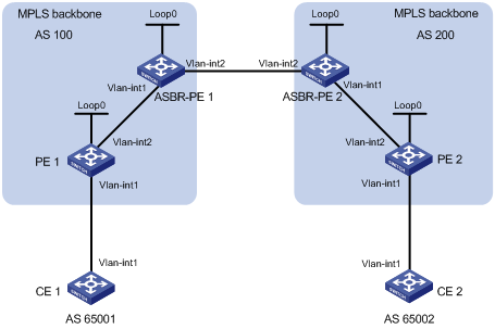
Network Diagram
Figure 3-2 Configure inter-provider VPN option A
|
Device |
Interface |
IP address |
Device |
Interface |
IP address |
|
CE 1 |
Vlan-int1 |
10.1.1.1/24 |
CE 2 |
Vlan-int1 |
10.2.1.1/24 |
|
PE 1 |
Loop0 |
1.1.1.9/32 |
PE 2 |
Loop0 |
4.4.4.9/32 |
|
|
Vlan-int1 |
10.1.1.2/24 |
|
Vlan-int1 |
10.2.1.2/24 |
|
|
Vlan-int2 |
172.1.1.2/24 |
|
Vlan-int2 |
162.1.1.2/24 |
|
ASBR-PE 1 |
Loop0 |
2.2.2.9/32 |
ASBR-PE 2 |
Loop0 |
3.3.3.9/32 |
|
|
Vlan-int1 |
172.1.1.1/24 |
|
Vlan-int1 |
162.1.1.1/24 |
|
|
Vlan-int2 |
192.1.1.1/24 |
|
Vlan-int2 |
192.1.1.2/24 |
Networking and Configuration Requirements
l CE 1 and CE 2 belong to the same VPN. CE 1 accesses the network through PE 1 in AS 100 and CE 2 accesses the network through PE 2 in AS 200.
l Inter-provider MPLS L3VPN is implemented using option A. That is, the VRF-to-VRF method is used to manage VPN routes.
l The MPLS backbone in each AS runs OSPF.
Applicable Product Matrix
|
Product series |
Software version |
Hardware version |
|
S7500E Series Ethernet Switches |
Release 6300, |
LSQ1SRP1CB SRPU(s), or exclusively EA series LPUs |
Configuration Procedure
1) Configure IGP on the MPLS backbone, implementing the connectivity in the backbone
This example uses OSPF. The detailed configuration steps are omitted.
![]()
The 32-bit loopback interface address used as the LSR ID needs to be advertised by OSPF.
After you complete the above configurations, each ASBR PE and the PE in the same AS should be able to establish OSPF adjacencies. Issuing the display ospf peer command, you can see that the adjacencies reach the state of Full, and that PEs can learn the loopback addresses of each other.
Each ASBR PE and the PE in the same AS should be able to ping each other.
2) Configure MPLS basic capability and MPLS LDP on the MPLS backbone to establish LDP LSPs
# Configure MPLS basic capability on PE 1 and enable MPLS LDP on the interface connected to ASBR PE 1.
<PE1> system-view
[PE1] mpls lsr-id 1.1.1.9
[PE1] mpls
[PE1-mpls] quit
[PE1] mpls ldp
[PE1-mpls-ldp] quit
[PE1] interface vlan-interface 1
[PE1-Vlan-interface1] mpls
[PE1-Vlan-interface1] mpls ldp
[PE1-Vlan-interface1] quit
# Configure MPLS basic capability on ASBR PE 1 and enable MPLS LDP on the interface connected to PE 1.
<ASBR-PE1> system-view
[ASBR-PE1] mpls lsr-id 2.2.2.9
[ASBR-PE1] mpls
[ASBR-PE1-mpls] quit
[ASBR-PE1] mpls ldp
[ASBR-PE1-mpls-ldp] quit
[ASBR-PE1] interface vlan-interface 1
[ASBR-PE1-Vlan-interface1] mpls
[ASBR-PE1-Vlan-interface1] mpls ldp
[ASBR-PE1-Vlan-interface1] quit
# Configure MPLS basic capability on ASBR PE 2 and enable MPLS LDP on the interface connected to PE 2.
<ASBR-PE2> system-view
[ASBR-PE2] mpls lsr-id 3.3.3.9
[ASBR-PE2] mpls
[ASBR-PE2-mpls] quit
[ASBR-PE2] mpls ldp
[ASBR-PE2-mpls-ldp] quit
[ASBR-PE2] interface vlan-interface 1
[ASBR-PE2-Vlan-interface1] mpls
[ASBR-PE2-Vlan-interface1] mpls ldp
[ASBR-PE2-Vlan-interface1] quit
# Configure MPLS basic capability on PE 2 and enable MPLS LDP on the interface connected to ASBR PE 2.
<PE2> system-view
[PE2] mpls lsr-id 4.4.4.9
[PE2] mpls
[PE2-mpls] quit
[PE2] mpls ldp
[PE2-mpls-ldp] quit
[PE2] interface vlan-interface 2
[PE2-Vlan-interface2] mpls
[PE2-Vlan-interface2] mpls ldp
[PE2-Vlan-interface2] quit
After you complete the above configurations, each PE and the ASBR PE in the same AS should be able to establish neighbor relationship. Issuing the display mpls ldp session command on the devices, you can see that the Session State field has a value of Operational in the output information.
3) Configure VPN instances on PEs to allow CEs to access
![]()
The VPN targets for the VPN instances of the PEs must match those for the VPN instances of the ASBR-PEs in the same AS. It is not required for PEs in different ASs.
# Configure CE 1.
<CE1> system-view
[CE1] interface vlan-interface 1
[CE1-Vlan-interface1] ip address 10.1.1.1 24
[CE1-Vlan-interface1] quit
# Configure PE 1.
[PE1] ip vpn-instance vpn1
[PE1-vpn-instance-vpn1] route-distinguisher 100:1
[PE1-vpn-instance-vpn1] vpn-target 100:1 both
[PE1-vpn-instance-vpn1] quit
[PE1] interface vlan-interface 1
[PE1-Vlan-interface1] ip binding vpn-instance vpn1
[PE1-Vlan-interface1] ip address 10.1.1.2 24
[PE1-Vlan-interface1] quit
# Configure CE 2.
<CE2> system-view
[CE2] interface vlan-interface 1
[CE2-Vlan-interface1] ip address 10.2.1.1 24
[CE2-Vlan-interface1] quit
# Configure PE 2.
[PE2] ip vpn-instance vpn1
[PE2-vpn-instance] route-distinguisher 200:2
[PE2-vpn-instance] vpn-target 100:1 both
[PE2-vpn-instance] quit
[PE2] interface vlan-interface 1
[PE2-Vlan-interface1] ip binding vpn-instance vpn1
[PE2-Vlan-interface1] ip address 10.2.1.2 24
[PE2-Vlan-interface1] quit
# Configure ASBR PE 1, creating a VPN instance and binding the instance to the interface connected with ASBR PE 2. Note that ASBR PE 1 considers ASBR PE 2 its CE.
[ASBR-PE1] ip vpn-instance vpn1
[ASBR-PE1-vpn-instance-vpn1] route-distinguisher 100:1
[ASBR-PE1-vpn-instance-vpn1] vpn-target 100:1 both
[ASBR-PE1-vpn-instance-vpn1] quit
[ASBR-PE1] interface vlan-interface 2
[ASBR-PE1-Vlan-interface2] ip binding vpn-instance vpn1
[ASBR-PE1-Vlan-interface2] ip address 192.1.1.1 24
[ASBR-PE1-Vlan-interface2] quit
# Configure ASBR PE 2, creating a VPN instance and binding the instance to the interface connected with ASBR PE 1. Note that ASBR PE 2 considers ASBR PE 1 its CE.
[ASBR-PE2] ip vpn-instance vpn1
[ASBR-PE2-vpn-vpn-vpn1] route-distinguisher 200:1
[ASBR-PE2-vpn-vpn-vpn1] vpn-target 100:1 both
[ASBR-PE2-vpn-vpn-vpn1] quit
[ASBR-PE2] interface vlan-interface 2
[ASBR-PE2-Vlan-interface2] ip binding vpn-instance vpn1
[ASBR-PE2-Vlan-interface2] ip address 192.1.1.2 24
[ASBR-PE2-Vlan-interface2] quit
After completing the above configurations, you should see the VPN instance configurations by issuing the display ip vpn-instance command.
The PEs should be able to ping the CEs and the ASBR PEs should be able to ping each other.
4) Establish EBGP peer relationship between PEs and CEs to allow VPN routes to be injected
# Configure CE 1.
[CE1] bgp 65001
[CE1-bgp] peer 10.1.1.2 as-number 100
[CE1-bgp] import-route direct
[CE1-bgp] quit
# Configure PE 1.
[PE1] bgp 100
[PE1-bgp] ipv4-family vpn-instance vpn1
[PE1-bgp-vpn1] peer 10.1.1.1 as-number 65001
[PE1-bgp-vpn1] import-route direct
[PE1-bgp-vpn1] quit
[PE1-bgp] quit
# Configure CE 2.
[CE2] bgp 65002
[CE2-bgp] peer 10.2.1.2 as-number 200
[CE2-bgp] import-route direct
[CE2-bgp] quit
# Configure PE 2.
[PE2] bgp 200
[PE2-bgp] ipv4-family vpn-instance vpn1
[PE2-bgp-vpn1] peer 10.2.1.1 as-number 65002
[PE2-bgp-vpn1] import-route direct
[PE2-bgp-vpn1] quit
[PE2-bgp] quit
5) Establish IBGP peer relationship between each PE and the ASBR PE in the same AS and EBGP peer relationship between the ASBR PEs
# Configure PE 1.
[PE1] bgp 100
[PE1-bgp] peer 2.2.2.9 as-number 100
[PE1-bgp] peer 2.2.2.9 connect-interface loopback 0
[PE1-bgp] ipv4-family vpnv4
[PE1-bgp-af-vpnv4] peer 2.2.2.9 enable
[PE1-bgp-af-vpnv4] peer 2.2.2.9 next-hop-local
[PE1-bgp-af-vpnv4] quit
[PE1-bgp] quit
# Configure ASBR PE 1.
[ASBR-PE1] bgp 100
[ASBR-PE1-bgp] ipv4-family vpn-instance vpn1
[ASBR-PE1-bgp-vpn1] peer 192.1.1.2 as-number 200
[ASBR-PE1-bgp-vpn1] quit
[ASBR-PE1-bgp] peer 1.1.1.9 as-number 100
[ASBR-PE1-bgp] peer 1.1.1.9 connect-interface loopback 0
[ASBR-PE1-bgp] ipv4-family vpnv4
[ASBR-PE1-bgp-af-vpnv4] peer 1.1.1.9 enable
[ASBR-PE1-bgp-af-vpnv4] peer 1.1.1.9 next-hop-local
[ASBR-PE1-bgp-af-vpnv4] quit
[ASBR-PE1-bgp] quit
# Configure ASBR PE 2.
[ASBR-PE2] bgp 200
[ASBR-PE2-bgp] ipv4-family vpn-instance vpn1
[ASBR-PE2-bgp-vpn1] peer 192.1.1.1 as-number 100
[ASBR-PE2-bgp-vpn1] quit
[ASBR-PE2-bgp] peer 4.4.4.9 as-number 200
[ASBR-PE2-bgp] peer 4.4.4.9 connect-interface loopback 0
[ASBR-PE2-bgp] ipv4-family vpnv4
[ASBR-PE2-bgp-af-vpnv4] peer 4.4.4.9 enable
[ASBR-PE2-bgp-af-vpnv4] peer 4.4.4.9 next-hop-local
[ASBR-PE2-bgp-af-vpnv4] quit
[ASBR-PE2-bgp] quit
# Configure PE 2.
[PE2] bgp 200
[PE2-bgp] peer 3.3.3.9 as-number 200
[PE2-bgp] peer 3.3.3.9 connect-interface loopback 0
[PE2-bgp] ipv4-family vpnv4
[PE2-bgp-af-vpnv4] peer 3.3.3.9 enable
[PE2-bgp-af-vpnv4] peer 3.3.3.9 next-hop-local
[PE2-bgp-af-vpnv4] quit
[PE2-bgp] quit
6) Verify your configurations
After you complete the above configurations, the CEs should be able to learn the interface routes from each other and ping each other.
Complete Configuration
l Configuration on CE 1
#
interface Vlan-interface1
ip address 10.1.1.1 255.255.255.0
#
bgp 65001
peer 10.1.1.2 as-number 100
import-route direct
l Configuration on PE 1
#
mpls lsr-id 1.1.1.9
#
ip vpn-instance vpn1
route-distinguisher 100:1
vpn-target 100:1 export-extcommunity
vpn-target 100:1 import-extcommunity
#
mpls
lsp-trigger all
#
mpls ldp
#
interface LoopBack0
ip address 1.1.1.9 255.255.255.255
#
interface Vlan-interface1
ip binding vpn-instance vpn1
ip address 10.1.1.2 255.255.255.0
mpls
mpls ldp
#
interface Vlan-interface2
ip address 172.1.1.2 255.255.255.0
mpls
mpls ldp
#
ospf 1
area 0
network 10.1.1.0 0.0.0.255
network 172.1.1.0 0.0.0.255
network 1.1.1.9 0.0.0.0
#
bgp 100
undo synchronization
peer 2.2.2.9 as-number 100
peer 2.2.2.9 connect-interface LoopBack0
#
ipv4-family vpn-instance vpn1
peer 10.1.1.1 as-number 65001
import-route direct
#
ipv4-family vpnv4
peer 2.2.2.9 enable
peer 2.2.2.9 next-hop-local
l Configuration on ASBR-PE 1
#
mpls lsr-id 2.2.2.9
#
ip vpn-instance vpn1
route-distinguisher 100:1
vpn-target 100:1 export-extcommunity
vpn-target 100:1 import-extcommunity
#
mpls
lsp-trigger all
#
mpls ldp
#
interface LoopBack0
ip address 2.2.2.9 255.255.255.255
#
interface Vlan-interface1
ip address 172.1.1.1 255.255.255.0
mpls
mpls ldp
#
interface Vlan-interface2
ip binding vpn-instance vpn1
ip address 192.1.1.1 255.255.255.0
mpls
mpls ldp
#
ospf 1
area 0
network 172.1.1.0 0.0.0.255
network 192.1.1.0 0.0.0.255
network 2.2.2.9 0.0.0.0
#
bgp 100
undo synchronization
peer 1.1.1.9 as-number 100
peer 1.1.1.9 connect-interface LoopBack0
#
ipv4-family vpn-instance vpn1
peer 192.1.1.2 as-number 200
import-route direct
#
ipv4-family vpnv4
peer 1.1.1.9 enable
peer 1.1.1.9 next-hop-local
l Configuration on ASBR-PE 2
#
mpls lsr-id 3.3.3.9
#
ip vpn-instance vpn1
route-distinguisher 200:1
vpn-target 100:1 export-extcommunity
vpn-target 100:1 import-extcommunity
#
mpls
lsp-trigger all
#
mpls ldp
#
interface LoopBack0
ip address 3.3.3.9 255.255.255.255
#
interface Vlan-interface1
ip address 162.1.1.1 255.255.255.0
mpls
mpls ldp
#
interface Vlan-interface2
ip binding vpn-instance vpn1
ip address 192.1.1.2 255.255.255.0
mpls
mpls ldp
#
ospf 1
area 0
network 162.1.1.0 0.0.0.255
network 192.1.1.0 0.0.0.255
network 3.3.3.9 0.0.0.0
#
bgp 200
undo synchronization
peer 4.4.4.9 as-number 200
peer 4.4.4.9 connect-interface LoopBack0
#
ipv4-family vpn-instance vpn1
peer 192.1.1.1 as-number 100
import-route direct
#
ipv4-family vpnv4
peer 4.4.4.9 enable
peer 4.4.4.9 next-hop-local
l Configuration on PE 2
#
mpls lsr-id 4.4.4.9
#
ip vpn-instance vpn1
route-distinguisher 200:2
vpn-target 100:1 export-extcommunity
vpn-target 100:1 import-extcommunity
#
mpls
lsp-trigger all
#
mpls ldp
#
interface LoopBack0
ip address 4.4.4.9 255.255.255.255
#
interface Vlan-interface1
ip binding vpn-instance vpn1
ip address 10.2.1.2 255.255.255.0
mpls
mpls ldp
#
interface Vlan-interface2
ip address 162.1.1.2 255.255.255.0
mpls
mpls ldp
#
ospf 1
area 0
network 10.2.1.0 0.0.0.255
network 162.1.1.0 0.0.0.255
network 4.4.4.9 0.0.0.0
#
bgp 200
undo synchronization
peer 3.3.3.9 as-number 200
peer 3.3.3.9 connect-interface LoopBack0
#
ipv4-family vpn-instance vpn1
peer 10.2.1.1 as-number 65002
import-route direct
#
ipv4-family vpnv4
peer 3.3.3.9 enable
peer 3.3.3.9 next-hop-local
l Configuration on CE 2
#
interface Vlan-interface1
ip address 10.2.1.1 255.255.255.0
#
bgp 65002
peer 10.2.1.2 as-number 200
import-route direct
Configuration Guidelines
In the inter-provider VPN option A solution, for the same VPN, the VPN targets for the VPN instances of the PEs must match those for the VPN instances of the ASBR-PEs in the same AS. It is not required for PEs in different ASs.
Configuring Inter-Provider VPN Option B
Network Diagram
Figure 3-3 Configure inter-provider VPN option B
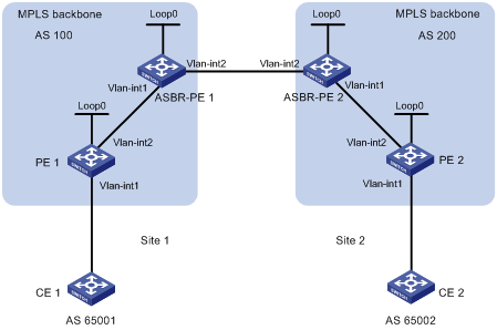
|
Device |
Interface |
IP address |
Device |
Interface |
IP address |
|
PE 1 |
Loop0 |
2.2.2.9/32 |
PE 2 |
Loop0 |
5.5.5.9/32 |
|
|
Vlan-int1 |
30.0.0.1/8 |
|
Vlan-int1 |
20.0.0.1/8 |
|
|
Vlan-int2 |
1.1.1.2/8 |
|
Vlan-int2 |
9.1.1.2/8 |
|
ASBR-PE 1 |
Loop0 |
3.3.3.9/32 |
ASBR-PE 2 |
Loop0 |
4.4.4.9/32 |
|
|
Vlan-int1 |
1.1.1.1/8 |
|
Vlan-int1 |
9.1.1.1/8 |
|
|
Vlan-int2 |
11.0.0.2/8 |
|
Vlan-int2 |
11.0.0.1/8 |
Networking and Configuration Requirements
l Site 1 and Site 2 belong to the same VPN. CE 1 of Site 1 accesses the network through PE 1 in AS 100 and CE 2 of Site 2 accesses the network through PE 2 in AS 600.
l PEs in the same AS runs IS-IS between them.
l PE 1 and ASBR-PE 1 exchange labeled IPv4 routes by MP-IBGP.
l PE 2 and ASBR-PE 2 exchange labeled IPv4 routes by MP-IBGP.
l ASBR-PE 1 and ASBR-PE 2 exchange labeled IPv4 routes by MP-EBGP.
l ASBRs do not perform VPN target filtering of received VPN-IPv4 routes.
Applicable Product Matrix
|
Product series |
Software version |
Hardware version |
|
S7500E Series Ethernet Switches |
Release 6300, |
LSQ1SRP1CB SRPU(s), or exclusively EA series LPUs |
Configuration Procedure
In the inter-provider VPN option B solution, configurations on CEs are similar to those in the inter-provider VPN option A solution. The configuration steps on CEs are omitted.
1) Configure PE 1
# Run IS-IS on PE 1.
<PE1> system-view
[PE1] isis 1
[PE1-isis-1] network-entity 10.111.111.111.111.00
[PE1-isis-1] quit
# Configure LSR ID, enable MPLS and LDP.
[PE1] mpls lsr-id 2.2.2.9
[PE1] mpls
[PE1-mpls] label advertise non-null
[PE1-mpls] quit
[PE1] mpls ldp
[PE1-mpls-ldp] quit
# Configure interface VLAN-interface 2, start IS-IS and enable MPLS and LDP on the interface.
[PE1] interface vlan-interface 2
[PE1-Vlan-interface2] ip address 1.1.1.2 255.0.0.0
[PE1-Vlan-interface2] isis enable 1
[PE1-Vlan-interface2] mpls
[PE1-Vlan-interface2] mpls ldp
[PE1-Vlan-interface2] quit
# Configure interface Loopback 0 and start IS-IS on it.
[PE1] interface loopback 0
[PE1-LoopBack0] ip address 2.2.2.9 32
[PE1-LoopBack0] isis enable 1
[PE1-LoopBack0] quit
# Create VPN instance vpn1 and configure the RD and VPN target attributes.
[PE1] ip vpn-instance vpn1
[PE1-vpn-instance-vpn1] route-distinguisher 11:11
[PE1-vpn-instance-vpn1] vpn-target 1:1 2:2 3:3 import-extcommunity
[PE1-vpn-instance-vpn1] vpn-target 3:3 export-extcommunity
[PE1-vpn-instance-vpn1] quit
# Bind the interface connected with CE 1 to the created VPN instance.
[PE1] interface vlan-interface 1
[PE1-Vlan-interface1] ip binding vpn-instance vpn1
[PE1-Vlan-interface1] ip address 30.0.0.1 8
[PE1-Vlan-interface1] quit
# Start BGP on PE 1.
[PE1] bgp 100
# Configure IBGP peer 3.3.3.9 as a VPNv4 peer.
[PE1-bgp] peer 3.3.3.9 as-number 100
[PE1-bgp] peer 3.3.3.9 connect-interface loopback 0
[PE1-bgp] ipv4-family vpnv4
[PE1-bgp-af-vpnv4] peer 3.3.3.9 enable
[PE1-bgp-af-vpnv4] quit
# Specify to inject direct routes to the VPN routing table of vpn1.
[PE1-bgp] ipv4-family vpn-instance vpn1
[PE1-bgp-vpn1] import-route direct
[PE1-bgp-vpn1] quit
[PE1-bgp] quit
2) Configure ASBR-PE 1
# Start IS-IS on ASBR-PE 1.
<ASBR-PE1> system-view
[ASBR-PE1] isis 1
[ASBR-PE1-isis-1] network-entity 10.222.222.222.222.00
[ASBR-PE1-isis-1] quit
# Configure LSR ID, enable MPLS and LDP.
[ASBR-PE1] mpls lsr-id 3.3.3.9
[ASBR-PE1] mpls
[ASBR-PE1-mpls] label advertise non-null
[ASBR-PE1-mpls] quit
[ASBR-PE1] mpls ldp
[ASBR-PE1-mpls-ldp] quit
# Configure interface VLAN-interface 1, start IS-IS and enable MPLS and LDP on the interface.
[ASBR-PE1] interface vlan-interface 1
[ASBR-PE1-Vlan-interface1] ip address 1.1.1.1 255.0.0.0
[ASBR-PE1-Vlan-interface1] isis enable 1
[ASBR-PE1-Vlan-interface1] mpls
[ASBR-PE1-Vlan-interface1] mpls ldp
[ASBR-PE1-Vlan-interface1] quit
# Configure interface VLAN-interface 2 and enable MPLS on it.
[ASBR-PE1] interface vlan-interface 2
[ASBR-PE1-Vlan-interface2] ip address 11.0.0.2 255.0.0.0
[ASBR-PE1-Vlan-interface2] mpls
[ASBR-PE1-Vlan-interface2] quit
# Configure interface Loopback 0 and start IS-IS on it.
[ASBR-PE1] interface loopback 0
[ASBR-PE1-LoopBack0] ip address 3.3.3.9 32
[ASBR-PE1-LoopBack0] isis enable 1
[ASBR-PE1-LoopBack0] quit
# Start BGP on ASBR-PE 1.
[ASBR-PE1] bgp 100
[ASBR-PE1-bgp] peer 2.2.2.9 as-number 100
[ASBR-PE1-bgp] peer 2.2.2.9 connect-interface loopback 0
[ASBR-PE1-bgp] peer 11.0.0.1 as-number 600
[ASBR-PE1-bgp] peer 11.0.0.1 connect-interface vlan-interface 2
# Specify not to filter the received VPNv4 routes using the import target attribute.
[ASBR-PE1-bgp] ipv4-family vpnv4
[ASBR-PE1-bgp-af-vpnv4] undo policy vpn-target
# Configure both IBGP peer 2.2.2.0 and EBGP peer 11.0.0.1 as VPNv4 peers.
[ASBR-PE1-bgp-af-vpnv4] peer 11.0.0.1 enable
[ASBR-PE1-bgp-af-vpnv4] peer 2.2.2.9 enable
[ASBR-PE1-bgp-af-vpnv4] quit
3) Configure ASBR-PE 2
# Start IS-IS on ASBR-PE 2.
<ASBR-PE2> system-view
[ASBR-PE2] isis 1
[ASBR-PE2-isis-1] network-entity 10.222.222.222.222.00
[ASBR-PE2-isis-1] quit
# Configure LSR ID, enable MPLS and LDP.
[ASBR-PE2] mpls lsr-id 4.4.4.9
[ASBR-PE2] mpls
[ASBR-PE2-mpls] label advertise non-null
[ASBR-PE2-mpls] quit
[ASBR-PE2] mpls ldp
[ASBR-PE2-mpls-ldp] quit
# Configure interface VLAN-interface 1, start IS-IS and enable MPLS and LDP on the interface.
[ASBR-PE2] interface vlan-interface 1
[ASBR-PE2-Vlan-interface1] ip address 9.1.1.1 255.0.0.0
[ASBR-PE2-Vlan-interface1] isis enable 1
[ASBR-PE2-Vlan-interface1] mpls
[ASBR-PE2-Vlan-interface1] mpls ldp
[ASBR-PE2-Vlan-interface1] quit
# Configure interface VLAN-interface 2 and enable MPLS on it.
[ASBR-PE2] interface vlan-interface 2
[ASBR-PE2-Vlan-interface2] ip address 11.0.0.1 255.0.0.0
[ASBR-PE2-Vlan-interface2] mpls
[ASBR-PE2-Vlan-interface2] quit
# Configure interface Loopback 0 and start IS-IS on it.
[ASBR-PE2] interface loopback 0
[ASBR-PE2-LoopBack0] ip address 4.4.4.9 32
[ASBR-PE2-LoopBack0] isis enable 1
[ASBR-PE2-LoopBack0] quit
# Start BGP on ASBR-PE 2.
[ASBR-PE2] bgp 600
[ASBR-PE2-bgp] peer 11.0.0.2 as-number 100
[ASBR-PE2-bgp] peer 11.0.0.2 connect-interface vlan-interface 2
[ASBR-PE2-bgp] peer 5.5.5.9 as-number 600
[ASBR-PE2-bgp] peer 5.5.5.9 connect-interface loopback 0
# Specify not to filter the received VPNv4 routes using the import target attribute.
[ASBR-PE2-bgp] ipv4-family vpnv4
[ASBR-PE2-bgp-af-vpnv4] undo policy vpn-target
# Configure both IBGP peer 5.5.5.9 and EBGP peer 11.0.0.2 as VPNv4 peers.
[ASBR-PE2-bgp-af-vpnv4] peer 11.0.0.2 enable
[ASBR-PE2-bgp-af-vpnv4] peer 5.5.5.9 enable
[ASBR-PE2-bgp-af-vpnv4] quit
[ASBR-PE2-bgp] quit
4) Configure PE 2
# Start IS-IS on PE 2.
<PE2> system-view
[PE2] isis 1
[PE2-isis-1] network-entity 10.111.111.111.111.00
[PE2-isis-1] quit
# Configure LSR ID, enable MPLS and LDP.
[PE2] mpls lsr-id 5.5.5.9
[PE2] mpls
[PE2-mpls] label advertise non-null
[PE2-mpls] quit
[PE2] mpls ldp
[PE2-mpls-ldp] quit
# Configure interface VLAN-interface 2, start IS-IS and enable MPLS and LDP on the interface.
[PE2] interface vlan-interface 2
[PE2-Vlan-interface2] ip address 9.1.1.2 255.0.0.0
[PE2-Vlan-interface2] isis enable 1
[PE2-Vlan-interface2] mpls
[PE2-Vlan-interface2] mpls ldp
[PE2-Vlan-interface2] quit
# Configure interface Loopback 0 and start IS-IS on it.
[PE2] interface loopback 0
[PE2-LoopBack0] ip address 5.5.5.9 32
[PE2-LoopBack0] isis enable 1
[PE2-LoopBack0] quit
# Create VPN instance vpn1 and configure the RD and VPN target attributes.
[PE2] ip vpn-instance vpn1
[PE2-vpn-instance-vpn1] route-distinguisher 12:12
[PE2-vpn-instance-vpn1] vpn-target 1:1 2:2 3:3 import-extcommunity
[PE2-vpn-instance-vpn1] vpn-target 3:3 export-extcommunity
[PE2-vpn-instance-vpn1] quit
# Bind the interface connected with CE 2 to the created VPN instance.
[PE2] interface vlan-interface 1
[PE2-Vlan-interface1] ip binding vpn-instance vpn1
[PE2-Vlan-interface1] ip address 20.0.0.1 8
[PE2-Vlan-interface1] quit
# Start BGP on PE 2.
[PE2] bgp 600
# Configure IBGP peer 4.4.4.9 as a VPNv4 peer.
[PE2-bgp] peer 4.4.4.9 as-number 600
[PE2-bgp] peer 4.4.4.9 connect-interface loopback 0
[PE2-bgp] ipv4-family vpnv4
[PE2-bgp-af-vpnv4] peer 4.4.4.9 enable
[PE2-bgp-af-vpnv4] quit
# Specify to inject direct routes to the VPN routing table of vpn1.
[PE2-bgp] ipv4-family vpn-instance vpn1
[PE2-bgp-vpn1] import-route direct
[PE2-bgp-vpn1] quit
[PE2-bgp] quit
5) Verify your configurations
After you complete the above configurations, PE 1 and PE 2 should be able to ping each other.
Complete Configuration
l Configuration on PE 1
#
mpls lsr-id 2.2.2.9
#
ip vpn-instance vpn1
route-distinguisher 11:11
vpn-target 3:3 export-extcommunity
vpn-target 1:1 2:2 3:3 import-extcommunity
#
mpls
label advertise non-null
lsp-trigger all
#
mpls ldp
#
isis 1
network-entity 10.1111.1111.1111.00
#
interface LoopBack0
ip address 2.2.2.9 255.255.255.255
isis enable 1
#
interface Vlan-interface1
ip binding vpn-instance vpn1
ip address 30.0.0.1 255.0.0.0
#
interface Vlan-interface2
ip address 1.1.1.2 255.0.0.0
isis enable 1
mpls
mpls ldp
#
bgp 100
undo synchronization
peer 3.3.3.9 as-number 100
peer 3.3.3.9 connect-interface LoopBack0
#
ipv4-family vpn-instance vpn1
import-route direct
#
ipv4-family vpnv4
peer 3.3.3.9 enable
l Configuration on ASBR-PE 1
#
mpls lsr-id 3.3.3.9
#
mpls
label advertise non-null
lsp-trigger all
#
mpls ldp
#
isis 1
network-entity 10.2222.2222.2222.00
#
interface LoopBack0
ip address 3.3.3.9 255.255.255.255
isis enable 1
#
interface Vlan-interface1
ip address 1.1.1.1 255.0.0.0
isis enable 1
mpls
mpls ldp
#
interface Vlan-interface2
ip address 11.0.0.2 255.0.0.0
mpls
#
bgp 100
undo synchronization
peer 2.2.2.9 as-number 100
peer 2.2.2.9 connect-interface LoopBack0
peer 11.0.0.1 as-number 600
peer 11.0.0.1 connect-interface Vlan-interface 2
#
ipv4-family vpnv4
peer 2.2.2.9 enable
peer 11.0.0.1 enable
undo policy vpn-target
l Configuration on ASBR-PE 2
#
mpls lsr-id 4.4.4.9
#
mpls
label advertise non-null
lsp-trigger all
#
mpls ldp
#
isis 1
network-entity 10.2222.2222.2222.00
#
interface LoopBack0
ip address 4.4.4.9 255.255.255.255
isis enable 1
#
interface Vlan-interface1
ip address 9.1.1.1 255.0.0.0
isis enable 1
mpls
mpls ldp
#
interface Vlan-interface2
ip address 11.0.0.1 255.0.0.0
mpls
#
bgp 600
undo synchronization
peer 5.5.5.9 as-number 600
peer 5.5.5.9 connect-interface LoopBack0
peer 11.0.0.2 as-number 100
peer 11.0.0.2 connect-interface Vlan-interface 2
#
ipv4-family vpnv4
peer 5.5.5.9 enable
peer 11.0.0.2 enable
undo policy vpn-target
l Configuration on PE 2
#
mpls lsr-id 5.5.5.9
#
ip vpn-instance vpn1
route-distinguisher 12:12
vpn-target 3:3 export-extcommunity
vpn-target 1:1 2:2 3:3 import-extcommunity
#
mpls
label advertise non-null
lsp-trigger all
#
mpls ldp
#
isis 1
network-entity 10.1111.1111.1111.00
#
interface LoopBack0
ip address 5.5.5.9 255.255.255.255
isis enable 1
#
interface Vlan-interface1
ip binding vpn-instance vpn1
ip address 20.0.0.1 255.0.0.0
#
interface Vlan-interface2
ip address 9.1.1.2 255.0.0.0
isis enable 1
mpls
mpls ldp
#
bgp 600
undo synchronization
peer 4.4.4.9 as-number 600
peer 4.4.4.9 connect-interface LoopBack0
#
ipv4-family vpn-instance vpn1
import-route direct
#
ipv4-family vpnv4
peer 4.4.4.9 enable
Configuration Guidelines
In the inter-provider VPN option B solution, for the same VPN, the VPN targets for the VPN instances of the PEs must match those for the VPN instances of the ASBR-PEs in the same AS. This is also true for PEs in different ASs.
Configuring Inter-Provider VPN Option C
Network Diagram
Figure 3-4 Configure inter-provider VPN option C
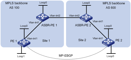
|
Device |
Interface |
IP address |
Device |
Interface |
IP address |
|
PE 1 |
Loop0 |
2.2.2.9/32 |
PE 2 |
Loop0 |
5.5.5.9/32 |
|
|
Loop1 |
30.0.0.1/32 |
|
Loop1 |
20.0.0.1/32 |
|
|
Vlan-int1 |
1.1.1.2/8 |
|
Vlan-int1 |
9.1.1.2/8 |
|
ASBR-PE 1 |
Loop0 |
3.3.3.9/32 |
ASBR-PE 2 |
Loop0 |
4.4.4.9/32 |
|
|
Vlan-int1 |
1.1.1.1/8 |
|
Vlan-int1 |
9.1.1.1/8 |
|
|
Vlan-int2 |
11.0.0.2/8 |
|
Vlan-int2 |
11.0.0.1/8 |
Networking and Configuration Requirements
l Site 1 and Site 2 belong to the same VPN. Site 1 accesses the network through PE 1 in AS 100 and Site 2 accesses the network through PE 2 in AS 600.
l PEs in the same AS runs IS-IS between them.
l PE 1 and ASBR-PE 1 exchange labeled IPv4 routes by MP-IBGP.
l PE 2 and ASBR-PE 2 exchange labeled IPv4 routes by MP-IBGP.
l PE 1 and PE 2 are MP-EBGP peers.
l ASBR-PE 1 and ASBR-PE 2 use their respective routing policies and label the routes received from each other.
l ASBR-PE 1 and ASBR-PE 2 use MP-EBGP to exchange labeled IPv4 routes.
Applicable Product Matrix
|
Product series |
Software version |
Hardware version |
|
S7500E Series Ethernet Switches |
Release 6300, |
LSQ1SRP1CB SRPU(s), or exclusively EA series LPUs |
Configuration Procedure
1) Configure PE 1
# Run IS-IS on PE 1.
<PE1> system-view
[PE1] isis 1
[PE1-isis-1] network-entity 10.111.111.111.111.00
[PE1-isis-1] quit
# Configure LSR ID, enable MPLS and LDP.
[PE1] mpls lsr-id 2.2.2.9
[PE1] mpls
[PE1-mpls] quit
[PE1] mpls ldp
[PE1-mpls-ldp] quit
# Configure interface VLAN-interface 1, start IS-IS and enable MPLS and LDP on the interface.
[PE1] interface vlan-interface 1
[PE1-Vlan-interface1] ip address 1.1.1.2 255.0.0.0
[PE1-Vlan-interface1] isis enable 1
[PE1-Vlan-interface1] mpls
[PE1-Vlan-interface1] mpls ldp
[PE1-Vlan-interface1] quit
# Configure interface Loopback 0 and start IS-IS on it.
[PE1] interface loopback 0
[PE1-LoopBack0] ip address 2.2.2.9 32
[PE1-LoopBack0] isis enable 1
[PE1-LoopBack0] quit
# Create VPN instance vpn1 and configure the RD and VPN target attributes.
[PE1] ip vpn-instance vpn1
[PE1-vpn-instance-vpn1] route-distinguisher 11:11
[PE1-vpn-instance-vpn1] vpn-target 1:1 2:2 3:3 import-extcommunity
[PE1-vpn-instance-vpn1] vpn-target 3:3 export-extcommunity
[PE1-vpn-instance-vpn1] quit
# Configure interface Loopback 1 and bind the interface to VPN instance vpn1.
[PE1] interface loopback 1
[PE1-LoopBack1] ip binding vpn-instance vpn1
[PE1-LoopBack1] ip address 30.0.0.1 32
[PE1-LoopBack1] quit
# Start BGP on PE 1.
[PE1] bgp 100
# Configure the capability to advertise labeled routes to IBGP peer 3.3.3.9 and to receive labeled routes from the peer.
[PE1-bgp] peer 3.3.3.9 as-number 100
[PE1-bgp] peer 3.3.3.9 connect-interface loopback 0
[PE1-bgp] peer 3.3.3.9 label-route-capability
# Configure the maximum hop count from PE 1 to EBGP peer 5.5.5.9 as 10.
[PE1-bgp] peer 5.5.5.9 as-number 600
[PE1-bgp] peer 5.5.5.9 connect-interface loopback 0
[PE1-bgp] peer 5.5.5.9 ebgp-max-hop 10
# Configure peer 5.5.5.9 as a VPNv4 peer.
[PE1-bgp] ipv4-family vpnv4
[PE1-bgp-af-vpnv4] peer 5.5.5.9 enable
[PE1-bgp-af-vpnv4] quit
# Specify to inject direct routes to the routing table of vpn1.
[PE1-bgp] ipv4-family vpn-instance vpn1
[PE1-bgp-vpn1] import-route direct
[PE1-bgp-vpn1] quit
[PE1-bgp] quit
2) Configure ASBR-PE 1
# Start IS-IS on ASBR-PE 1.
<ASBR-PE1> system-view
[ASBR-PE1] isis 1
[ASBR-PE1-isis-1] network-entity 10.222.222.222.222.00
[ASBR-PE1-isis-1] quit
# Configure LSR ID, enable MPLS and LDP.
[ASBR-PE1] mpls lsr-id 3.3.3.9
[ASBR-PE1] mpls
[ASBR-PE1-mpls] quit
[ASBR-PE1] mpls ldp
[ASBR-PE1-mpls-ldp] quit
# Configure interface VLAN-interface 1, start IS-IS and enable MPLS and LDP on the interface.
[ASBR-PE1] interface vlan-interface 1
[ASBR-PE1-Vlan-interface1] ip address 1.1.1.1 255.0.0.0
[ASBR-PE1-Vlan-interface1] isis enable 1
[ASBR-PE1-Vlan-interface1] mpls
[ASBR-PE1-Vlan-interface1] mpls ldp
[ASBR-PE1-Vlan-interface1] quit
# Configure interface VLAN-interface 2 and enable MPLS on it.
[ASBR-PE1] interface vlan-interface 2
[ASBR-PE1-Vlan-interface2] ip address 11.0.0.2 255.0.0.0
[ASBR-PE1-Vlan-interface2] mpls
[ASBR-PE1-Vlan-interface2] quit
# Configure interface Loopback 0 and start IS-IS on it.
[ASBR-PE1] interface loopback 0
[ASBR-PE1-LoopBack0] ip address 3.3.3.9 32
[ASBR-PE1-LoopBack0] isis enable 1
[ASBR-PE1-LoopBack0] quit
# Create routing policies.
[ASBR-PE1] route-policy policy1 permit node 1
[ASBR-PE1-route-policy1] apply mpls-label
[ASBR-PE1-route-policy1] quit
[ASBR-PE1] route-policy policy2 permit node 1
[ASBR-PE1-route-policy2] if-match mpls-label
[ASBR-PE1-route-policy2] apply mpls-label
[ASBR-PE1-route-policy2] quit
# Start BGP on ASBR-PE 1 and specify to inject routes of IS-IS process 1.
[ASBR-PE1] bgp 100
[ASBR-PE1-bgp] import-route isis 1
# Specify to use routing policy policy2 to filter routes advertised from IBGP peer 2.2.2.9.
[ASBR-PE1-bgp] peer 2.2.2.9 as-number 100
[ASBR-PE1-bgp] peer 2.2.2.9 route-policy policy2 export
# Configure the capability to advertise labeled routes to IBGP peer 2.2.2.9 and to receive labeled routes from the peer.
[ASBR-PE1-bgp] peer 2.2.2.9 connect-interface loopback 0
[ASBR-PE1-bgp] peer 2.2.2.9 label-route-capability
# Specify to use routing policy policy1 to filter routes advertised from EBGP peer 11.0.0.1.
[ASBR-PE1-bgp] peer 11.0.0.1 as-number 600
[ASBR-PE1-bgp] peer 11.0.0.1 route-policy policy1 export
# Configure the capability to advertise labeled routes to EBGP peer 11.0.0.1 and to receive labeled routes from the peer.
[ASBR-PE1-bgp] peer 11.0.0.1 label-route-capability
[ASBR-PE1-bgp] quit
3) Configure ASBR-PE 2
# Start IS-IS on ASBR-PE 2.
<ASBR-PE2> system-view
[ASBR-PE2] isis 1
[ASBR-PE2-isis-1] network-entity 10.222.222.222.222.00
[ASBR-PE2-isis-1] quit
# Configure LSR ID, enable MPLS and LDP.
[ASBR-PE2] mpls lsr-id 4.4.4.9
[ASBR-PE2] mpls
[ASBR-PE2-mpls] quit
[ASBR-PE2] mpls ldp
[ASBR-PE2-mpls-ldp] quit
# Configure interface VLAN-interface 1, start IS-IS and enable MPLS and LDP on the interface.
[ASBR-PE2] interface vlan-interface 1
[ASBR-PE2-Vlan-interface1] ip address 9.1.1.1 255.0.0.0
[ASBR-PE2-Vlan-interface1] isis enable 1
[ASBR-PE2-Vlan-interface1] mpls
[ASBR-PE2-Vlan-interface1] mpls ldp
[ASBR-PE2-Vlan-interface1] quit
# Configure interface Loopback 0 and start IS-IS on it.
[ASBR-PE2] interface loopback 0
[ASBR-PE2-LoopBack0] ip address 4.4.4.9 32
[ASBR-PE2-LoopBack0] isis enable 1
[ASBR-PE2-LoopBack0] quit
# Configure interface VLAN-interface 2 and enable MPLS on it.
[ASBR-PE2] interface vlan-interface 2
[ASBR-PE2-Vlan-interface2] ip address 11.0.0.1 255.0.0.0
[ASBR-PE2-Vlan-interface2] mpls
[ASBR-PE2-Vlan-interface2] quit
# Create routing policies.
[ASBR-PE2] route-policy policy1 permit node 1
New Sequence of this List
[ASBR-PE2-route-policy1] apply mpls-label
[ASBR-PE2-route-policy1] quit
[ASBR-PE2] route-policy policy2 permit node 1
[ASBR-PE2-route-policy2] if-match mpls-label
[ASBR-PE2-route-policy2] apply mpls-label
[ASBR-PE2-route-policy2] quit
# Start BGP on ASBR-PE 2 and specify to inject routes of IS-IS process 1.
[ASBR-PE2] bgp 600
[ASBR-PE2-bgp] import-route isis 1
# Configure the capability to advertise labeled routes to IBGP peer 5.5.5.9 and to receive labeled routes from the peer.
[ASBR-PE2-bgp] peer 5.5.5.9 as-number 600
[ASBR-PE2-bgp] peer 5.5.5.9 connect-interface loopback 1
[ASBR-PE2-bgp] peer 5.5.5.9 label-route-capability
# Specify to use routing policy policy2 to filter routes advertised from IBGP peer 5.5.5.9.
[ASBR-PE2-bgp] peer 5.5.5.9 route-policy policy2 export
# Specify to use routing policy policy1 to filter routes advertised from EBGP peer 11.0.0.2.
[ASBR-PE2-bgp] peer 11.0.0.2 as-number 100
[ASBR-PE2-bgp] peer 11.0.0.2 route-policy policy1 export
# Configure the capability to advertise labeled routes to EBGP peer 11.0.0.2 and to receive labeled routes from the peer.
[ASBR-PE2-bgp] peer 11.0.0.2 label-route-capability
[ASBR-PE2-bgp] quit
4) Configure PE 2
# Start IS-IS on PE 2.
<PE2> system-view
[PE2] isis 1
[PE2-isis-1] network-entity 10.111.111.111.111.00
[PE2-isis-1] quit
# Configure LSR ID, enable MPLS and LDP.
[PE2] mpls lsr-id 5.5.5.9
[PE2] mpls
[PE2-mpls] quit
[PE2] mpls ldp
[PE2-mpls-ldp] quit
# Configure interface VLAN-interface 1, start IS-IS and enable MPLS and LDP on the interface.
[PE2] interface vlan-interface 1
[PE2-Vlan-interface1] ip address 9.1.1.2 255.0.0.0
[PE2-Vlan-interface1] isis enable 1
[PE2-Vlan-interface1] mpls
[PE2-Vlan-interface1] mpls ldp
[PE2-Vlan-interface1] quit
# Configure interface Loopback 0 and start IS-IS on it.
[PE2] interface loopback 0
[PE2-LoopBack0] ip address 5.5.5.9 32
[PE2-LoopBack0] isis enable 1
[PE2-LoopBack0] quit
# Create VPN instance vpn1 and configure the RD and VPN target attributes.
[PE2] ip vpn-instance vpn1
[PE2-vpn-instance-vpn1] route-distinguisher 11:11
[PE2-vpn-instance-vpn1] vpn-target 1:1 2:2 3:3 import-extcommunity
[PE2-vpn-instance-vpn1] vpn-target 3:3 export-extcommunity
[PE2-vpn-instance-vpn1] quit
# Configure interface Loopback 1 and bind the interface to VPN instance vpn1.
[PE2] interface loopback 1
[PE2-LoopBack1] ip binding vpn-instance vpn1
[PE2-LoopBack1] ip address 20.0.0.1 32
[PE2-LoopBack1] quit
# Start BGP on PE 2.
[PE2] bgp 600
# Configure the capability to advertise labeled routes to IBGP peer 4.4.4.9 and to receive labeled routes from the peer.
[PE2-bgp] peer 4.4.4.9 as-number 600
[PE2-bgp] peer 4.4.4.9 connect-interface loopback 1
[PE2-bgp] peer 4.4.4.9 label-route-capability
# Configure the maximum hop count from PE 2 to EBGP peer 2.2.2.9 as 10.
[PE2-bgp] peer 2.2.2.9 as-number 100
[PE2-bgp] peer 2.2.2.9 connect-interface loopback 1
[PE2-bgp] peer 2.2.2.9 ebgp-max-hop 10
# Configure peer 2.2.2.9 as a VPNv4 peer.
[PE2-bgp] ipv4-family vpnv4
[PE2-bgp-af-vpnv4] peer 2.2.2.9 enable
[PE2-bgp-af-vpnv4] quit
# Specify to inject direct routes to the routing table of vpn1.
[PE2-bgp] ipv4-family vpn-instance vpn1
[PE2-bgp-vpn1] import-route direct
[PE2-bgp-vpn1] quit
[PE2-bgp] quit
After you complete the above configurations, PE 1 and PE 2 should be able to ping each other:
[PE2] ping –vpn-instance vpn1 30.0.0.1
[PE1] ping –vpn-instance vpn1 20.0.0.1
Complete Configuration
l Configuration on PE 1
#
mpls lsr-id 2.2.2.9
#
ip vpn-instance vpn1
route-distinguisher 11:11
vpn-target 3:3 export-extcommunity
vpn-target 1:1 2:2 3:3 import-extcommunity
#
mpls
lsp-trigger all
#
mpls ldp
#
isis 1
network-entity 10.1111.1111.1111.00
#
interface LoopBack0
ip address 2.2.2.9 255.255.255.255
isis enable 1
#
interfaceLoopBack1
ip binding vpn-instance vpn1
ip address 30.0.0.1 255.255.255.255
#
interface Vlan-interface1
ip address 1.1.1.2 255.0.0.0
isis enable 1
mpls
mpls ldp
#
bgp 100
undo synchronization
peer 5.5.5.9 as-number 600
peer 3.3.3.9 as-number 100
peer 5.5.5.9 ebgp-max-hop 10
peer 5.5.5.9 connect-interface LoopBack0
peer 3.3.3.9 label-route-capability
peer 3.3.3.9 connect-interface LoopBack0
#
ipv4-family vpn-instance vpn1
import-route direct
#
ipv4-family vpnv4
peer 5.5.5.9 enable
l Configuration on ASBR-PE 1
#
mpls lsr-id 3.3.3.9
#
mpls
lsp-trigger all
#
mpls ldp
#
isis 1
network-entity 10.2222.2222.2222.00
#
interface LoopBack0
ip address 3.3.3.9 255.255.255.255
isis enable 1
#
interface Vlan-interface1
ip address 1.1.1.1 255.0.0.0
isis enable 1
mpls
mpls ldp
#
interface Vlan-interface2
ip address 11.0.0.2 255.0.0.0
mpls
#
bgp 100
import-route isis 1
undo synchronization
peer 11.0.0.1 as-number 600
peer 2.2.2.9 as-number 100
peer 11.0.0.1 route-policy policy1 export
peer 2.2.2.9 route-policy policy2 export
peer 11.0.0.1 label-route-capability
peer 2.2.2.9 label-route-capability
peer 2.2.2.9 connect-interface LoopBack0
#
route-policy policy1 permit node 1
apply mpls-label
route-policy policy2 permit node 1
if-match mpls-label
apply mpls-label
l Configuration on ASBR-PE 2
#
mpls lsr-id 4.4.4.9
#
mpls
lsp-trigger all
#
mpls ldp
#
isis 1
network-entity 10.2222.2222.2222.00
#
interface LoopBack0
ip address 4.4.4.9 255.255.255.255
isis enable 1
#
interface Vlan-interface1
ip address 9.1.1.1 255.0.0.0
isis enable 1
mpls
mpls ldp
#
interface Vlan-interface2
ip address 11.0.0.1 255.0.0.0
mpls
#
bgp 600
import-route isis 1
undo synchronization
peer 11.0.0.2 as-number 100
peer 5.5.5.9 as-number 600
peer 11.0.0.2 route-policy policy1 export
peer 5.5.5.9 route-policy policy2 export
peer 11.0.0.2 label-route-capability
peer 5.5.5.9 label-route-capability
peer 5.5.5.9 connect-interface LoopBack1
#
route-policy policy1 permit node 1
apply mpls-label
route-policy policy2 permit node 1
if-match mpls-label
apply mpls-label
l Configuration on PE 2
#
mpls lsr-id 5.5.5.9
#
ip vpn-instance vpn1
route-distinguisher 11:11
vpn-target 3:3 export-extcommunity
vpn-target 1:1 2:2 3:3 import-extcommunity
#
mpls
lsp-trigger all
#
mpls ldp
#
isis 1
network-entity 10.1111.1111.1111.00
#
interface LoopBack0
ip address 5.5.5.9 255.255.255.255
isis enable 1
#
interfaceLoopBack1
ip binding vpn-instance vpn1
ip address 20.0.0.1 255.255.255.255
#
interface Vlan-interface1
ip address 9.1.1.2 255.0.0.0
isis enable 1
mpls
mpls ldp
#
bgp 600
undo synchronization
peer 4.4.4.9 as-number 600
peer 2.2.2.9 as-number 100
peer 2.2.2.9 ebgp-max-hop 10
peer 4.4.4.9 connect-interface LoopBack1
peer 4.4.4.9 label-route-capability
peer 2.2.2.9 connect-interface LoopBack1
#
ipv4-family vpn-instance vpn1
import-route direct
#
ipv4-family vpnv4
peer 2.2.2.9 enable
Configuration Guidelines
None
Configuring Carrier’s Carrier
Network Diagram
Figure 3-5 Configure carrier’s carrier
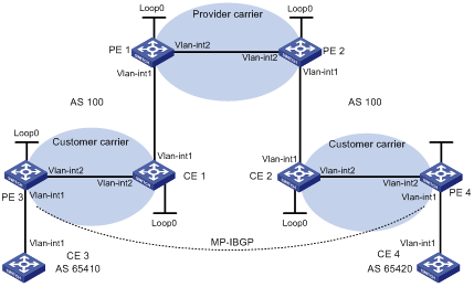
|
Interface |
IP address |
Device |
Interface |
IP address |
|
|
CE 3 |
Vlan-int1 |
100.1.1.1/24 |
CE 4 |
Vlan-int1 |
120.1.1.1/24 |
|
PE 3 |
Loop0 |
1.1.1.9/32 |
PE 4 |
Loop0 |
6.6.6.9/32 |
|
|
Vlan-int1 |
100.1.1.2/24 |
|
Vlan-int1 |
120.1.1.2/24 |
|
|
Vlan-int2 |
10.1.1.1/24 |
|
Vlan-int2 |
20.1.1.2/24 |
|
CE 1 |
Loop0 |
2.2.2.9/32 |
CE 2 |
Loop0 |
5.5.5.9/32 |
|
|
Vlan-int2 |
10.1.1.2/24 |
|
Vlan-int1 |
21.1.1.2/24 |
|
|
Vlan-int1 |
11.1.1.1/24 |
|
Vlan-int2 |
20.1.1.1/24 |
|
PE 1 |
Loop0 |
3.3.3.9/32 |
PE 2 |
Loop0 |
4.4.4.9/32 |
|
|
Vlan-int1 |
11.1.1.2/24 |
|
Vlan-int2 |
30.1.1.2/24 |
|
|
Vlan-int2 |
30.1.1.1/24 |
|
Vlan-int1 |
21.1.1.1/24 |
Networking and Configuration Requirements
The Level 2 carrier provides MPLS L3VPN services to customers.
As shown in Figure 3-5,
l PE 1 and PE 2 are PEs of the Level 1 carrier backbone.
l CE 1 and CE 2 are devices of the Level 2 carrier and work as CE to access the Level 1 carrier backbone.
l PE 3 and PE 4 are devices of the Level 2 carrier and work as PE to provide access service for the customers of the Level 2 carrier.
l CE 3 and CE 4 are customers of the Level 2 carrier.
Applicable Product Matrix
|
Product series |
Software version |
Hardware version |
|
S7500E Series Ethernet Switches |
Release 6300, |
LSQ1SRP1CB SRPU(s), or exclusively EA series LPUs |
Configuration Procedure
The key of the carrier’s carrier configuration lies in the exchange process of two kinds of routes:
l The exchange of the internal Level 2 carrier VPN routes on the Level 1 carrier backbone. In this process, the Level 2 carrier accesses the Level 1 carrier backbone as CE.
l The exchange of customer VPN routes of the Level 2 carrier between PEs of the Level 2 carrier. In this process, MP-IBGP peer relationship must be established between the PEs of the Level 2 carrier (that is, between PE 3 and PE 4).
1) Configure MPLS L3VPN on the Level 1 carrier backbone: start IS-IS as the IGP, enable LDP between PE 1 and PE 2, and establish MP-IBGP peer relationship between the PEs
# Configure PE 1.
<PE1> system-view
[PE1] interface loopback 0
[PE1-LoopBack0] ip address 3.3.3.9 32
[PE1-LoopBack0] quit
[PE1] mpls lsr-id 3.3.3.9
[PE1] mpls
[PE1-mpls] quit
[PE1] mpls ldp
[PE1-mpls-ldp] quit
[PE1] isis 1
[PE1-isis-1] network-entity 10.0000.0000.0000.0004.00
[PE1-isis-1] quit
[PE1] interface loopback 0
[PE1-LoopBack0] isis enable 1
[PE1-LoopBack0] quit
[PE1] interface vlan-interface 2
[PE1-Vlan-interface2] ip address 30.1.1.1 24
[PE1-Vlan-interface2] isis enable 1
[PE1-Vlan-interface2] mpls
[PE1-Vlan-interface2] mpls ldp
[PE1-Vlan-interface2] mpls ldp transport-address interface
[PE1-Vlan-interface2] quit
[PE1] bgp 100
[PE1-bgp] peer 4.4.4.9 as-number 100
[PE1-bgp] peer 4.4.4.9 connect-interface loopback 0
[PE1-bgp] ipv4-family vpnv4
[PE1-bgp-af-vpnv4] peer 4.4.4.9 enable
[PE1-bgp-af-vpnv4] quit
[PE1-bgp] quit
![]()
The configurations for PE 2 are similar to those for PE 1. The detailed configuration steps are omitted.
After completing the above configurations, you should see that the LDP session has been established successfully by issuing the display mpls ldp session command on PE 1 or PE 2. Issuing the display bgp peer command, you should see that the BGP peer relationship has been established and has reached the state of Established. Issuing the display isis peer command, you should see that the IS-IS neighbor relationship has been set up. Take PE 1 as an example:
[PE1] display mpls ldp session
LDP Session(s) in Public Network
----------------------------------------------------------------
Peer-ID Status LAM SsnRole FT MD5 KA-Sent/Rcv
----------------------------------------------------------------
4.4.4.9:0 Operational DU Active Off Off 378/378
----------------------------------------------------------------
LAM : Label Advertisement Mode FT : Fault Tolerance
[PE1] display bgp peer
BGP local router ID : 3.3.3.9
Local AS number : 100
Total number of peers : 1 Peers in established state : 1
Peer V AS MsgRcvd MsgSent OutQ PrefRcv Up/Down State
4.4.4.9 4 100 162 145 0 0 02:12:47 Established
[PE1] display isis peer
Peer information for ISIS(1)
----------------------------
System Id Interface Circuit Id State HoldTime Type PRI
0000.0000.0005 Vlan-interface2 001 Up 29s L1L2 --
2) Configure the Level 2 carrier network: start IS-IS as the IGP and enable LDP between PE 3 and CE 1, and between PE 4 and CE 2 respectively
# Configure PE 3.
<PE3> system-view
[PE3] interface loopback 0
[PE3-LoopBack0] ip address 1.1.1.9 32
[PE3-LoopBack0] quit
[PE3] mpls lsr-id 1.1.1.9
[PE3] mpls
[PE3-mpls] quit
[PE3] mpls ldp
[PE3-mpls-ldp] quit
[PE3] isis 2
[PE3-isis-2] network-entity 10.0000.0000.0000.0001.00
[PE3-isis-2] quit
[PE3] interface loopback 0
[PE3-LoopBack0] isis enable 2
[PE3-LoopBack0] quit
[PE3] interface vlan-interface 2
[PE3-Vlan-interface2] ip address 10.1.1.1 24
[PE3-Vlan-interface2] isis enable 2
[PE3-Vlan-interface2] mpls
[PE3-Vlan-interface2] mpls ldp
[PE3-Vlan-interface2] mpls ldp transport-address interface
[PE3-Vlan-interface2] quit
# Configure CE 1.
<CE1> system-view
[CE1] interface loopback 0
[CE1-LoopBack0] ip address 2.2.2.9 32
[CE1-LoopBack0] quit
[CE1] mpls lsr-id 2.2.2.9
[CE1] mpls
[CE1-mpls] quit
[CE1] mpls ldp
[CE1-mpls-ldp] quit
[CE1] isis 2
[CE1-isis-2] network-entity 10.0000.0000.0000.0002.00
[CE1-isis-2] quit
[CE1] interface loopback 0
[CE1-LoopBack0] isis enable 2
[CE1-LoopBack0] quit
[CE1] interface vlan-interface 2
[CE1-Vlan-interface2] ip address 10.1.1.2 24
[CE1-Vlan-interface2] isis enable 2
[CE1-Vlan-interface2] mpls
[CE1-Vlan-interface2] mpls ldp
[CE1-Vlan-interface2] mpls ldp transport-address interface
[CE1-Vlan-interface2] quit
After you complete the above configurations, PE 3 and CE 1 should be able to establish the LDP session and IS-IS neighbor relationship between them.
![]()
The configurations for PE 4 and CE 2 are similar to those for PE 3 and CE 1. The detailed configuration steps are omitted.
3) Perform configuration to allow CEs of the Level 2 carrier to access PEs of the Level 1 carrier
# Configure PE 1 and inject IS-IS routes.
[PE1] ip vpn-instance vpn1
[PE1-vpn-instance-vpn1] route-distinguisher 200:1
[PE1-vpn-instance-vpn1] vpn-target 1:1
[PE1-vpn-instance-vpn1] quit
[PE1] mpls ldp vpn-instance vpn1
[PE1-mpls-ldp-vpn-instance-vpn1] quit
[PE1] isis 2 vpn-instance vpn1
[PE1-isis-2] network-entity 10.0000.0000.0000.0003.00
[PE1-isis-2] import-route bgp
[PE1-isis-2] quit
[PE1] interface vlan-interface 1
[PE1-Vlan-interface1] ip binding vpn-instance vpn1
[PE1-Vlan-interface1] ip address 11.1.1.2 24
[PE1-Vlan-interface1] isis enable 2
[PE1-Vlan-interface1] mpls
[PE1-Vlan-interface1] mpls ldp
[PE1-Vlan-interface1] mpls ldp transport-address interface
[PE1-Vlan-interface1] quit
[PE1] bgp 100
[PE1-bgp] ipv4-family vpn-instance vpn1
[PE1-bgp-vpn1] import isis 2
[PE1-bgp-vpn1] quit
[PE1-bgp] quit
# Configure CE 1.
[CE1] interface vlan-interface 1
[CE1-Vlan-interface1] ip address 11.1.1.1 24
[CE1-Vlan-interface1] isis enable 2
[CE1-Vlan-interface1] mpls
[CE1-Vlan-interface1] mpls ldp
[CE1-Vlan-interface1] mpls ldp transport-address interface
[CE1-Vlan-interface1] quit
After you complete the above configurations, PE 1 and CE 1 should be able to establish the LDP session and IS-IS neighbor relationship between them.
![]()
The configurations for PE 2 and CE 2 are similar to those for PE 1 and CE 1. The detailed configuration steps are omitted.
4) Perform configuration to allow the CEs of the Level 2 carrier to access the PEs
# Configure CE 3.
<CE3> system-view
[CE3] interface vlan-interface 1
[CE3-Vlan-interface1] ip address 100.1.1.1 24
[CE3-Vlan-interface1] quit
[CE3] bgp 65410
[CE3-bgp] peer 100.1.1.2 as-number 100
[CE3-bgp] import-route direct
[CE3-bgp] quit
# Configure PE 3.
[PE3] ip vpn-instance vpn1
[PE3-vpn-instance-vpn1] route-distinguisher 100:1
[PE3-vpn-instance-vpn1] vpn-target 1:1
[PE3-vpn-instance-vpn1] quit
[PE3] interface vlan-interface 1
[PE3-Vlan-interface1] ip binding vpn-instance vpn1
[PE3-Vlan-interface1] ip address 100.1.1.2 24
[PE3-Vlan-interface1] quit
[PE3] bgp 100
[PE3-bgp] ipv4-family vpn-instance vpn1
[PE3-bgp-vpn1] peer 100.1.1.1 as-number 65410
[PE3-bgp-vpn1] import-route direct
[PE3-bgp-vpn1] quit
[PE3-bgp] quit
![]()
The configurations for PE 4 and CE 4 are similar to those for PE 3 and CE 3. The detailed configuration steps are omitted.
5) Configure MP-IBGP peer relationship between PEs of the Level 2 carrier to exchange the VPN routes of the Level 2 carrier customers
# Configure PE 3.
[PE3] bgp 100
[PE3-bgp] peer 6.6.6.9 as-number 100
[PE3-bgp] peer 6.6.6.9 connect-interface loopback 0
[PE3-bgp] ipv4-family vpnv4
[PE3-bgp-af-vpnv4] peer 6.6.6.9 enable
[PE3-bgp-af-vpnv4] quit
[PE3-bgp] quit
![]()
The configurations for PE 4 are similar to those for PE 3. The detailed configuration steps are omitted.
6) Verify your configurations
After completing all the above configurations, you can issue the display ip routing-table command on PE 1 and PE 2. You should see that only routes of the Level 1 carrier network are present in the public network routing table of PE 1 and PE 2. Takes PE 1 as an example:
[PE1] display ip routing-table
Routing Tables: Public
Destinations : 7 Routes : 7
Destination/Mask Proto Pre Cost NextHop Interface
3.3.3.9/32 Direct 0 0 127.0.0.1 InLoop0
4.4.4.9/32 ISIS 15 10 30.1.1.2 Vlan2
30.1.1.0/24 Direct 0 0 30.1.1.1 Vlan2
30.1.1.1/32 Direct 0 0 127.0.0.1 InLoop0
30.1.1.2/32 Direct 0 0 30.1.1.2 Vlan2
127.0.0.0/8 Direct 0 0 127.0.0.1 InLoop0
127.0.0.1/32 Direct 0 0 127.0.0.1 InLoop0
Issuing the display ip routing-table vpn-instance command on PE 1 and PE 2, you should see that the internal routes of the Level 2 carrier network are present in the VPN routing tables, but the VPN routes that the Level 2 carrier maintains are not. Takes PE 1 as an example:
[PE1] display ip routing-table vpn-instance vpn1
Routing Tables: vpn1
Destinations : 11 Routes : 11
Destination/Mask Proto Pre Cost NextHop Interface
1.1.1.9/32 ISIS 15 20 11.1.1.1 Vlan1
2.2.2.9/32 ISIS 15 10 11.1.1.1 Vlan1
5.5.5.9/32 BGP 255 0 4.4.4.9 NULL0
6.6.6.9/32 BGP 255 0 4.4.4.9 NULL0
10.1.1.0/24 ISIS 15 20 11.1.1.1 Vlan1
11.1.1.0/24 Direct 0 0 11.1.1.1 Vlan1
11.1.1.1/32 Direct 0 0 127.0.0.1 InLoop0
11.1.1.2/32 Direct 0 0 11.1.1.2 Vlan1
20.1.1.0/24 BGP 255 0 4.4.4.9 NULL0
21.1.1.0/24 BGP 255 0 4.4.4.9 NULL0
21.1.1.2/32 BGP 255 0 4.4.4.9 NULL0
Issuing the display ip routing-table command on CE 1 and CE 2, you should see that the internal routes of the Level 2 carrier network are present in the public network routing tables, but the VPN routes that the Level 2 carrier maintains are not. Takes CE 1 as an example:
[CE1] display ip routing-table
Routing Tables: Public
Destinations : 16 Routes : 16
Destination/Mask Proto Pre Cost NextHop Interface
1.1.1.9/32 ISIS 15 10 10.1.1.2 Vlan2
2.2.2.9/32 Direct 0 0 127.0.0.1 InLoop0
5.5.5.9/32 ISIS 15 74 11.1.1.2 Vlan1
6.6.6.9/32 ISIS 15 74 11.1.1.2 Vlan1
10.1.1.0/24 Direct 0 0 10.1.1.2 Vlan2
10.1.1.1/32 Direct 0 0 10.1.1.1 Vlan2
10.1.1.2/32 Direct 0 0 127.0.0.1 InLoop0
11.1.1.0/24 Direct 0 0 11.1.1.1 Vlan1
11.1.1.1/32 Direct 0 0 127.0.0.1 InLoop0
11.1.1.2/32 Direct 0 0 11.1.1.2 Vlan1
20.1.1.0/24 ISIS 15 74 11.1.1.2 Vlan1
21.1.1.0/24 ISIS 15 74 11.1.1.2 Vlan1
21.1.1.2/32 ISIS 15 74 11.1.1.2 Vlan1
127.0.0.0/8 Direct 0 0 127.0.0.1 InLoop0
127.0.0.1/32 Direct 0 0 127.0.0.1 InLoop0
Issuing the display ip routing-table command on PE 3 and PE 4, you should see that the internal routes of the Level 2 carrier network are present in the public network routing tables. Takes PE 3 as an example:
[PE3] display ip routing-table
Routing Tables: Public
Destinations : 11 Routes : 11
Destination/Mask Proto Pre Cost NextHop Interface
1.1.1.9/32 Direct 0 0 127.0.0.1 InLoop0
2.2.2.9/32 ISIS 15 10 10.1.1.2 Vlan2
5.5.5.9/32 ISIS 15 84 10.1.1.2 Vlan2
6.6.6.9/32 ISIS 15 84 10.1.1.2 Vlan2
10.1.1.0/24 Direct 0 0 10.1.1.1 Vlan2
10.1.1.1/32 Direct 0 0 127.0.0.1 InLoop0
10.1.1.2/32 Direct 0 0 10.1.1.2 Vlan2
11.1.1.0/24 ISIS 15 20 10.1.1.2 Vlan2
20.1.1.0/24 ISIS 15 84 10.1.1.2 Vlan2
21.1.1.0/24 ISIS 15 84 10.1.1.2 Vlan2
21.1.1.2/32 ISIS 15 84 10.1.1.2 Vlan2
127.0.0.0/8 Direct 0 0 127.0.0.1 InLoop0
127.0.0.1/32 Direct 0 0 127.0.0.1 InLoop0
Issuing the display ip routing-table vpn-instance command on PE 3 and PE 4, you should see that the routes of the remote VPN customers are present in the VPN routing tables. Takes PE 3 as an example:
[PE3] display ip routing-table vpn-instance vpn1
Routing Tables: vpn1
Destinations : 3 Routes : 3
Destination/Mask Proto Pre Cost NextHop Interface
100.1.1.0/24 Direct 0 0 100.1.1.2 Vlan1
100.1.1.2/32 Direct 0 0 127.0.0.1 InLoop0
120.1.1.0/24 BGP 255 0 6.6.6.9 NULL0
PE 3 and PE 4 should be able to ping each other:
[PE3] ping 20.1.1.2
PING 20.1.1.2: 56 data bytes, press CTRL_C to break
Reply from 20.1.1.2: bytes=56 Sequence=1 ttl=252 time=127 ms
Reply from 20.1.1.2: bytes=56 Sequence=2 ttl=252 time=97 ms
Reply from 20.1.1.2: bytes=56 Sequence=3 ttl=252 time=83 ms
Reply from 20.1.1.2: bytes=56 Sequence=4 ttl=252 time=70 ms
Reply from 20.1.1.2: bytes=56 Sequence=5 ttl=252 time=60 ms
--- 20.1.1.2 ping statistics ---
5 packet(s) transmitted
5 packet(s) received
0.00% packet loss
round-trip min/avg/max = 60/87/127 ms
CE 3 and CE 4 should be able to ping each other:
[CE3] ping 120.1.1.1
PING 120.1.1.1: 56 data bytes, press CTRL_C to break
Reply from 120.1.1.1: bytes=56 Sequence=1 ttl=252 time=102 ms
Reply from 120.1.1.1: bytes=56 Sequence=2 ttl=252 time=69 ms
Reply from 120.1.1.1: bytes=56 Sequence=3 ttl=252 time=105 ms
Reply from 120.1.1.1: bytes=56 Sequence=4 ttl=252 time=88 ms
Reply from 120.1.1.1: bytes=56 Sequence=5 ttl=252 time=87 ms
--- 120.1.1.1 ping statistics ---
5 packet(s) transmitted
5 packet(s) received
0.00% packet loss
round-trip min/avg/max = 69/90/105 ms
Complete Configuration
l Configuration on PE 1
#
mpls lsr-id 3.3.3.9
#
ip vpn-instance vpn1
route-distinguisher 200:1
vpn-target 1:1 export-extcommunity
vpn-target 1:1 import-extcommunity
#
mpls
lsp-trigger all
#
mpls ldp
#
mpls ldp vpn-instance vpn1
#
isis 1
network-entity 10.0000.0000.0000.0004.00
#
isis 2 vpn-instance vpn1
network-entity 10.0000.0000.0000.0003.00
import-route bgp
#
interface LoopBack0
ip address 3.3.3.9 255.255.255.255
isis enable 1
#
interface Vlan-interface1
ip binding vpn-instance vpn1
ip address 11.1.1.2 255.255.255.0
isis enable 2
mpls
mpls ldp
mpls ldp transport-address interface
#
interface Vlan-interface2
ip address 30.1.1.1 255.255.255.0
isis enable 1
mpls
mpls ldp
mpls ldp transport-address interface
#
bgp 100
undo synchronization
peer 4.4.4.9 as-number 100
peer 4.4.4.9 connect-interface LoopBack0
#
ipv4-family vpn-instance vpn1
import-route isis 2
#
ipv4-family vpnv4
peer 4.4.4.9 enable
l Configuration on PE 2
#
mpls lsr-id 4.4.4.9
#
ip vpn-instance vpn1
route-distinguisher 200:1
vpn-target 1:1 export-extcommunity
vpn-target 1:1 import-extcommunity
#
mpls
lsp-trigger all
#
mpls ldp
#
mpls ldp vpn-instance vpn1
#
isis 1
network-entity 10.0000.0000.0000.0004.00
#
isis 2 vpn-instance vpn1
network-entity 10.0000.0000.0000.0003.00
import-route bgp
#
interface LoopBack0
ip address 4.4.4.9 255.255.255.255
isis enable 1
#
interface Vlan-interface1
ip binding vpn-instance vpn1
ip address 21.1.1.1 255.255.255.0
isis enable 2
mpls
mpls ldp
mpls ldp transport-address interface
#
interface Vlan-interface2
ip address 30.1.1.2 255.255.255.0
isis enable 1
mpls
mpls ldp
mpls ldp transport-address interface
#
bgp 100
undo synchronization
peer 3.3.3.9 as-number 100
peer 3.3.3.9 connect-interface LoopBack0
#
ipv4-family vpn-instance vpn1
import-route isis 2
#
ipv4-family vpnv4
peer 3.3.3.9 enable
l Configuration on CE 1
#
mpls lsr-id 2.2.2.9
#
mpls
lsp-trigger all
#
mpls ldp
#
isis 2
network-entity 10.0000.0000.0000.0002.00
#
interface LoopBack0
ip address 2.2.2.9 255.255.255.255
isis enable 2
#
interface Vlan-interface1
ip binding vpn-instance vpn1
ip address 11.1.1.1 255.255.255.0
isis enable 2
mpls
mpls ldp
mpls ldp transport-address interface
#
interface Vlan-interface2
ip address 10.1.1.2 255.255.255.0
isis enable 2
mpls
mpls ldp
mpls ldp transport-address interface
l Configuration on CE 2
The complete configuration on CE 2 is similar to that on CE 1 expect the interface IP addresses and the route advertisement segments.
l Configuration on PE 3
#
mpls lsr-id 1.1.1.9
#
ip vpn-instance vpn1
route-distinguisher 100:1
vpn-target 1:1 export-extcommunity
vpn-target 1:1 import-extcommunity
#
mpls
lsp-trigger all
#
mpls ldp
#
mpls ldp vpn-instance vpn1
#
isis 2
network-entity 10.0000.0000.0000.0001.00
#
interface LoopBack0
ip address 1.1.1.9 255.255.255.255
isis enable 2
#
interface Vlan-interface1
ip binding vpn-instance vpn1
ip address 100.1.1.2 255.255.255.0
#
interface Vlan-interface2
ip address 10.1.1.1 255.255.255.0
isis enable 2
mpls
mpls ldp
mpls ldp transport-address interface
#
bgp 100
undo synchronization
peer 6.6.6.9 as-number 100
peer 6.6.6.9 connect-interface LoopBack0
#
ipv4-family vpn-instance vpn1
peer 100.1.1.1 as-number 65410
import-route direct
#
ipv4-family vpnv4
peer 6.6.6.9 enable
l Configuration on PE 4
The complete configuration on PE 4 is similar to that on PE 3 expect the interface IP addresses and the route advertisement segments.
l Configuration on CE 3
#
interface Vlan-interface1
ip address 100.1.1.1 255.255.255.0
#
bgp 65410
peer 100.1.1.2 as-number 100
import-route direct
l Configuration on CE 4
#
interface Vlan-interface1
ip address 120.1.1.1 255.255.255.0
#
bgp 65420
peer 120.1.1.2 as-number 100
import-route direct
Configuration Guidelines
None
Configuring Nested VPN
Network Diagram
Figure 3-6 Configure nested VPN
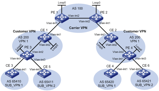
|
Device |
Interface |
IP address |
Device |
Interface |
IP address |
|
CE 1 |
Loop0 |
2.2.2.9/32 |
CE 2 |
Loop0 |
5.5.5.9/32 |
|
|
Vlan-int2 |
10.1.1.2/24 |
|
Vlan-int1 |
21.1.1.2/24 |
|
|
Vlan-int1 |
11.1.1.1/24 |
|
Vlan-int2 |
20.1.1.1/24 |
|
CE 3 |
Vlan-int1 |
100.1.1.1/24 |
CE 4 |
Vlan-int1 |
120.1.1.1/24 |
|
CE 5 |
Vlan-int3 |
110.1.1.1/24 |
CE 6 |
Vlan-int3 |
130.1.1.1/24 |
|
PE 1 |
Loop0 |
3.3.3.9/32 |
PE 2 |
Loop0 |
4.4.4.9/32 |
|
|
Vlan-int1 |
11.1.1.2/24 |
|
Vlan-int1 |
21.1.1.1/24 |
|
|
Vlan-int2 |
30.1.1.1/24 |
|
Vlan-int2 |
30.1.1.2/24 |
|
PE 3 |
Loop0 |
1.1.1.9/32 |
PE 4 |
Loop0 |
6.6.6.9/32 |
|
|
Vlan-int1 |
100.1.1.2/24 |
|
Vlan-int1 |
120.1.1.2/24 |
|
|
Vlan-int2 |
10.1.1.1/24 |
|
Vlan-int2 |
20.1.1.2/24 |
|
|
Vlan-int3 |
110.1.1.2/24 |
|
Vlan-int3 |
130.1.1.2/24 |
Networking and Configuration Requirements
The service provider provides nested VPN services for users, as shown in Figure 3-6, where:
l PE 1 and PE 2 are PE devices on the service provider backbone. Both of them support the nested VPN function.
l CE 1 and CE 2 are connected to the service provider backbone. Both of them support VPNv4 routes.
l PE 3 and PE 4 are PE devices of the customer VPN. Both of them support MPLS L3VPN.
l CE 3 through CE 6 are CE devices of the sub-VPNs for the customer VPN.
The key of nested VPN configuration is to understand the processing of routes of sub-VPNs on the service provider PEs, which is described as follows:
l When receiving a VPNv4 route from a CE (CE 1 or CE 2 in this example), a service provider PE replaces the RD of the VPNv4 route with the RD of the MPLS VPN on the service provider network where the CE resides, adds the export target attribute of the MPLS VPN on the service provider network to the extended community attribute list, and then forwards the VPNv4 route as usual.
l To implement exchange of sub-VPN routes between customer PEs and service provider PEs, MP-EBGP peers should be established between service provider PEs and customer CEs.
Applicable Product Matrix
|
Product series |
Software version |
Hardware version |
|
S7500E Series Ethernet Switches |
Release 6300, |
LSQ1SRP1CB SRPU(s), or exclusively EA series LPUs |
Configuration Procedure
1) Configure MPLS L3VPN on the service provider backbone, using IS-IS as the IGP protocol, and enabling LDP and establishing MP-IBGP peer relationship between PE 1 and PE 2.
# Configure PE 1.
<PE1> system-view
[PE1] interface loopback 0
[PE1-LoopBack0] ip address 3.3.3.9 32
[PE1-LoopBack0] quit
[PE1] mpls lsr-id 3.3.3.9
[PE1] mpls
[PE1-mpls] quit
[PE1] mpls ldp
[PE1-mpls-ldp] quit
[PE1] isis 1
[PE1-isis-1] network-entity 10.0000.0000.0000.0004.00
[PE1-isis-1] quit
[PE1] interface loopback 0
[PE1-LoopBack0] isis enable 1
[PE1-LoopBack0] quit
[PE1] interface vlan-interface 2
[PE1-Vlan-interface2] ip address 30.1.1.1 24
[PE1-Vlan-interface2] isis enable 1
[PE1-Vlan-interface2] mpls
[PE1-Vlan-interface2] mpls ldp
[PE1-Vlan-interface2] quit
[PE1] bgp 100
[PE1-bgp] peer 4.4.4.9 as-number 100
[PE1-bgp] peer 4.4.4.9 connect-interface loopback 0
[PE1-bgp] ipv4-family vpnv4
[PE1-bgp-af-vpnv4] peer 4.4.4.9 enable
[PE1-bgp-af-vpnv4] quit
[PE1-bgp] quit
![]()
Configurations on PE 2 are similar to those on PE 1, and are thus omitted here.
After completing the configurations above, you can execute commands display mpls ldp session, display bgp peer and display isis peer respectively on either PE 1 or PE 2. You should see that the LDP session is established, the BGP peer relationship is established and in the Established state, and the IS-IS neighbor relationship is established and up.
The following takes PE 1 for illustration.
[PE1] display mpls ldp session
LDP Session(s) in Public Network
----------------------------------------------------------------
Peer-ID Status LAM SsnRole FT MD5 KA-Sent/Rcv
----------------------------------------------------------------
4.4.4.9:0 Operational DU Active Off Off 378/378
----------------------------------------------------------------
LAM : Label Advertisement Mode FT : Fault Tolerance
[PE1] display bgp peer
BGP local router ID : 3.3.3.9
Local AS number : 100
Total number of peers : 1 Peers in established state : 1
Peer V AS MsgRcvd MsgSent OutQ PrefRcv Up/Down State
4.4.4.9 4 100 162 145 0 0 02:12:47 Established
[PE1] display isis peer
Peer information for ISIS(1)
----------------------------
System Id Interface Circuit Id State HoldTime Type PRI
0000.0000.0005 Vlan-interface2 001 Up 29s L1L2 --
2) Configure the customer VPN, using IS-IS as the IGP protocol and enabling LDP between PE 3 and CE 1, and between PE 4 and CE 2.
# Configure PE 3.
<PE3> system-view
[PE3] interface loopback 0
[PE3-LoopBack0] ip address 1.1.1.9 32
[PE3-LoopBack0] quit
[PE3] mpls lsr-id 1.1.1.9
[PE3] mpls
[PE3-mpls] quit
[PE3] mpls ldp
[PE3-mpls-ldp] quit
[PE3] isis 2
[PE3-isis-2] network-entity 10.0000.0000.0000.0001.00
[PE3-isis-2] quit
[PE3] interface loopback 0
[PE3-LoopBack0] isis enable 2
[PE3-LoopBack0] quit
[PE3-Vlan-interface2] ip address 10.1.1.1 24
[PE3-Vlan-interface2] isis enable 2
[PE3-Vlan-interface2] mpls
[PE3-Vlan-interface2] mpls ldp
[PE3-Vlan-interface2] quit
# Configure CE 1.
<CE1> system-view
[CE1] interface loopback 0
[CE1-LoopBack0] ip address 2.2.2.9 32
[CE1-LoopBack0] quit
[CE1] mpls lsr-id 2.2.2.9
[CE1] mpls
[CE1-mpls] quit
[CE1] mpls ldp
[CE1-mpls-ldp] quit
[CE1] isis 2
[CE1-isis-2] network-entity 10.0000.0000.0000.0002.00
[CE1-isis-2] quit
[CE1] interface loopback 0
[CE1-LoopBack0] isis enable 2
[CE1-LoopBack0] quit
[CE1] interface vlan-interface 2
[CE1-Vlan-interface2] ip address 10.1.1.2 24
[CE1-Vlan-interface2] isis enable 2
[CE1-Vlan-interface2] mpls
[CE1-Vlan-interface2] mpls ldp
[CE1-Vlan-interface2] quit
After the configurations above, LDP and IS-IS neighbor relationship can be established between PE 3 and CE 1.
![]()
Configurations on PE 4 and CE 2 are similar to those on PE 3 and CE 1 respectively, and are thus omitted here.
3) Connect CE 1 and CE 2 to service provider PEs.
# Configure PE 1.
[PE1] ip vpn-instance vpn1
[PE1-vpn-instance-vpn1] route-distinguisher 200:1
[PE1-vpn-instance-vpn1] vpn-target 1:1
[PE1-vpn-instance-vpn1] quit
[PE1] interface vlan-interface1
[PE1-Vlan-interface1] ip binding vpn-instance vpn1
[PE1-Vlan-interface1] ip address 11.1.1.2 24
[PE1-Vlan-interface1] mpls
[PE1-Vlan-interface1] quit
[PE1] bgp 100
[PE1-bgp] ipv4-family vpn-instance vpn1
[PE1-bgp-vpn1] peer 11.1.1.1 as-number 200
[PE1-bgp-vpn1] quit
[PE1-bgp] quit
# Configure CE 1.
[CE1] interface vlan-interface 1
[CE1-Vlan-interface1] ip address 11.1.1.1 24
[CE1-Vlan-interface1] mpls
[CE1-Vlan-interface1] quit
[CE1] bgp 200
[CE1-bgp] peer 11.1.1.2 as-number 100
[CE1-bgp] import isis 2
[CE1-bgp] quit
![]()
Configurations on PE 2 and CE 2 are similar to those on PE 1 and CE 1 respectively, and are thus omitted here.
4) Connect sub-VPN CEs to the customer VPN PEs
# Configure CE 3.
<CE3> system-view
[CE3] interface vlan-interface1
[CE3-Vlan-interface1] ip address 100.1.1.1 24
[CE3-Vlan-interface1] quit
[CE3] bgp 65410
[CE3-bgp] peer 100.1.1.2 as-number 200
[CE3-bgp] import-route direct
[CE3-bgp] quit
# Configure CE5.
<CE5> system-view
[CE5] interface vlan-interface 3
[CE5-Vlan-interface3] ip address 110.1.1.1 24
[CE5-Vlan-interface3] quit
[CE5] bgp 65411
[CE5-bgp] peer 110.1.1.2 as-number 200
[CE5-bgp] import-route direct
[CE5-bgp] quit
# Configure PE 3.
[PE3] ip vpn-instance SUB_VPN1
[PE3-vpn-instance-SUB_VPN1] route-distinguisher 100:1
[PE3-vpn-instance-SUB_VPN1] vpn-target 2:1
[PE3-vpn-instance-SUB_VPN1] quit
[PE3] interface vlan-interface 1
[PE3-Vlan-interface1] ip binding vpn-instance SUB_VPN1
[PE3-Vlan-interface1] ip address 100.1.1.2 24
[PE3-Vlan-interface1] quit
[PE3] ip vpn-instance SUB_VPN2
[PE3-vpn-instance-SUB_VPN2] route-distinguisher 101:1
[PE3-vpn-instance-SUB_VPN2] vpn-target 2:2
[PE3-vpn-instance-SUB_VPN2] quit
[PE3] interface vlan-interface 3
[PE3-Vlan-interface3] ip binding vpn-instance SUB_VPN2
[PE3-Vlan-interface3] ip address 110.1.1.2 24
[PE3-Vlan-interface3] quit
[PE3] bgp 200
[PE3-bgp] ipv4-family vpn-instance SUB_VPN1
[PE3-bgp-SUB_VPN1] peer 100.1.1.1 as-number 65410
[PE3-bgp-SUB_VPN1] import-route direct
[PE3-bgp-SUB_VPN1] quit
[PE3-bgp] ipv4-family vpn-instance SUB_VPN2
[PE3-bgp-SUB_VPN2] peer 100.1.1.1 as-number 65411
[PE3-bgp-SUB_VPN2] import-route direct
[PE3-bgp-SUB_VPN2] quit
[PE3-bgp] quit
![]()
Configurations on PE 4, CE 4 and CE6 are similar to those on PE 3, CE 3 and CE5 respectively, and are thus omitted here.
5) Establish MP-EBGP peer relationship between service provider PEs and their CEs to exchange user VPNv4 routes.
# Configure PE 1, enabling nested VPN.
[PE1] bgp 100
[PE1-bgp] ipv4-family vpnv4
[PE1-bgp-af-vpnv4] nesting-vpn
[PE1-bgp-af-vpnv4] peer 11.1.1.1 vpn-instance vpn1 enable
[PE1-bgp-af-vpnv4] quit
[PE1-bgp] quit
# Configure CE 1, enabling VPNv4 capability and establishing VPNv4 neighbor relationship between CE 1 and PE 1.
[CE1] bgp 200
[CE1-bgp] ipv4-family vpnv4
[CE1-bgp-af-vpnv4] peer 11.1.1.2 enable
# Specify to allow the local AS number to appear in the AS-PATH attribute of the routes received.
[CE1-bgp-af-vpnv4] peer 11.1.1.2 allow-as-loop 2
# Specify to receive all VPNv4 routes.
[CE1-bgp-af-vpnv4] undo policy vpn-target
[CE1-bgp-af-vpnv4] quit
[CE1-bgp] quit
![]()
Configurations on PE 2 and CE 2 are similar to those on PE 1 and CE 1 respectively, and are thus omitted here.
6) Establish MP-IBGP peer relationship between sub-VPN PEs and CEs of the customer VPN to exchange VPNv4 routes of sub-VPNs.
# Configure PE 3.
[PE3] bgp 200
[PE3-bgp] peer 2.2.2.9 as-number 200
[PE3-bgp] peer 2.2.2.9 connect-interface loopback 0
[PE3-bgp] ipv4-family vpnv4
[PE3-bgp-af-vpnv4] peer 2.2.2.9 enable
# Specify to allow the local AS number to appear in the AS-PATH attribute of the routes received.
[PE3-bgp-af-vpnv4] peer 2.2.2.9 allow-as-loop 2
[PE3-bgp-af-vpnv4] quit
[PE3-bgp] quit
# Configure CE 1.
[CE1] bgp 200
[CE1-bgp] peer 1.1.1.9 as-number 200
[CE1-bgp] peer 1.1.1.9 connect-interface loopback 0
[CE1-bgp] ipv4-family vpnv4
[CE1-bgp-af-vpnv4] peer 1.1.1.9 enable
[CE1-bgp-af-vpnv4] undo policy vpn-target
[CE1-bgp-af-vpnv4] quit
[CE1-bgp] quit
![]()
Configurations on PE 4 and CE 2 are similar to those on PE 3 and CE 1 respectively, and are thus omitted here.
7) Verify the configurations.
After completing all the configurations above, execute the display ip routing-table comand on PE 1 and PE 2 to verify that the public routing tables contain only routes on the service provider network. The following takes PE 1 for illustration.
[PE1] display ip routing-table
Routing Tables: Public
Destinations : 7 Routes : 7
Destination/Mask Proto Pre Cost NextHop Interface
3.3.3.9/32 Direct 0 0 127.0.0.1 InLoop0
4.4.4.9/32 ISIS 15 10 30.1.1.2 Vlan2
30.1.1.0/24 Direct 0 0 30.1.1.1 Vlan2
30.1.1.1/32 Direct 0 0 127.0.0.1 InLoop0
30.1.1.2/32 Direct 0 0 30.1.1.2 Vlan2
127.0.0.0/8 Direct 0 0 127.0.0.1 InLoop0
127.0.0.1/32 Direct 0 0 127.0.0.1 InLoop0
Execute the display ip routing-table vpn-instance command on PE 1 and PE 2 to verify that the VPN routing tables contain sub-VPN routes. The following takes PE 1 for illustration.
[PE1] display ip routing-table vpn-instance vpn1
Routing Tables: vpn1
Destinations : 9 Routes : 9
Destination/Mask Proto Pre Cost NextHop Interface
11.1.1.0/24 Direct 0 0 11.1.1.1 Vlan1
11.1.1.1/32 Direct 0 0 127.0.0.1 InLoop0
11.1.1.2/32 Direct 0 0 11.1.1.2 Vlan1
100.1.1.0/24 BGP 255 0 11.1.1.1 NULL0
110.1.1.0/24 BGP 255 0 11.1.1.1 NULL0
120.1.1.0/24 BGP 255 0 4.4.4.9 NULL0
127.0.0.0/8 Direct 0 0 127.0.0.1 InLoop0
127.0.0.1/32 Direct 0 0 127.0.0.1 InLoop0
130.1.1.0/24 BGP 255 0 4.4.4.9 NULL0
Execute the display bgp vpnv4 all routing-table command on CE 1 and CE 2 to verify that the VPNv4 routing tables on the customer VPN contain internal sub-VPN routes. The following takes CE 1 for illustration.
[CE1] display bgp vpnv4 all routing-table
BGP Local router ID is 11.11.11.11
Status codes: * - valid, > - best, d - damped,
h - history, i - internal, s - suppressed, S - Stale
Origin : i - IGP, e - EGP, ? - incomplete
Total number of routes from all PE: 4
Route Distinguisher: 100:1
Network NextHop In/Out Label MED LocPrf
*> 100.1.1.0/24 1.1.1.9 1024/1024
Route Distinguisher: 101:1
Network NextHop In/Out Label MED LocPrf
*> 110.1.1.0/24 1.1.1.9 1025/1025
Route Distinguisher: 200:1
Network NextHop In/Out Label MED LocPrf
*> 120.1.1.0/24 11.1.1.2 1026/1027
Route Distinguisher: 201:1
Network NextHop In/Out Label MED LocPrf
*> 130.1.1.0/24 11.1.1.2 1027/1028
Execute the display ip routing-table vpn-instance SUB_VPN1 command on PE 3 and PE 4 to verify that the VPN routing tables contain routes sent by the provider PE to user sub-VPN. The following takes PE 3 for illustration.
[PE3] display ip routing-table vpn-instance SUB_VPN1
Routing Tables: SUB_VPN1
Destinations : 5 Routes : 5
Destination/Mask Proto Pre Cost NextHop Interface
100.1.1.0/24 Direct 0 0 100.1.1.2 Vlan1
100.1.1.2/32 Direct 0 0 127.0.0.1 InLoop0
120.1.1.0/24 BGP 255 0 2.2.2.9 NULL0
127.0.0.0/8 Direct 0 0 127.0.0.1 InLoop0
127.0.0.1/32 Direct 0 0 127.0.0.1 InLoop0
Execute the display ip routing-table command on CE 3 and CE 4 to verify that the routing tables contain routes of remote sub-VPNs. The following takes CE 3 for illustration.
[CE3] display ip routing-table
Routing Tables: Public
Destinations : 5 Routes : 5
Destination/Mask Proto Pre Cost NextHop Interface
100.1.1.0/24 Direct 0 0 100.1.1.1 Vlan1
100.1.1.1/32 Direct 0 0 127.0.0.1 InLoop0
120.1.1.0/24 BGP 255 0 100.1.1.2 Vlan1
127.0.0.0/8 Direct 0 0 127.0.0.1 InLoop0
127.0.0.1/32 Direct 0 0 127.0.0.1 InLoop0
Execute the display ip routing-table command on CE5 and CE6 to verify that the routing tables contain routes of remote sub-VPNs. The following takes CE5 for illustration.
[CE5] display ip routing-table
Routing Tables: Public
Destinations : 5 Routes : 5
Destination/Mask Proto Pre Cost NextHop Interface
110.1.1.0/24 Direct 0 0 110.1.1.1 Vlan1
110.1.1.1/32 Direct 0 0 127.0.0.1 InLoop0
127.0.0.0/8 Direct 0 0 127.0.0.1 InLoop0
127.0.0.1/32 Direct 0 0 127.0.0.1 InLoop0
130.1.1.0/24 BGP 255 0 110.1.1.2 Vlan1
CE 3 and CE 4 can ping each other successfully.
[CE3] ping 120.1.1.1
PING 120.1.1.1: 56 data bytes, press CTRL_C to break
Reply from 120.1.1.1: bytes=56 Sequence=1 ttl=252 time=102 ms
Reply from 120.1.1.1: bytes=56 Sequence=2 ttl=252 time=69 ms
Reply from 120.1.1.1: bytes=56 Sequence=3 ttl=252 time=105 ms
Reply from 120.1.1.1: bytes=56 Sequence=4 ttl=252 time=88 ms
Reply from 120.1.1.1: bytes=56 Sequence=5 ttl=252 time=87 ms
--- 120.1.1.1 ping statistics ---
5 packet(s) transmitted
5 packet(s) received
0.00% packet loss
round-trip min/avg/max = 69/90/105 ms
CE5 and CE6 can ping each other successfully.
[CE5] ping 130.1.1.1
PING 130.1.1.1: 56 data bytes, press CTRL_C to break
Reply from 130.1.1.1: bytes=56 Sequence=1 ttl=252 time=102 ms
Reply from 130.1.1.1: bytes=56 Sequence=2 ttl=252 time=69 ms
Reply from 130.1.1.1: bytes=56 Sequence=3 ttl=252 time=105 ms
Reply from 130.1.1.1: bytes=56 Sequence=4 ttl=252 time=88 ms
Reply from 130.1.1.1: bytes=56 Sequence=5 ttl=252 time=87 ms
--- 130.1.1.1 ping statistics ---
5 packet(s) transmitted
5 packet(s) received
0.00% packet loss
round-trip min/avg/max = 69/90/105 ms
CE 3 and CE6 cannot ping each other.
[CE3] ping 130.1.1.1
PING 130.1.1.1: 56 data bytes, press CTRL_C to break
Request time out
Request time out
Request time out
Request time out
Request time out
--- 130.1.1.1 ping statistics ---
5 packet(s) transmitted
0 packet(s) received
100.00% packet loss
Complete Configuration
l Configuration on PE 1
#
mpls lsr-id 3.3.3.9
#
ip vpn-instance vpn1
route-distinguisher 200:1
vpn-target 1:1 export-extcommunity
vpn-target 1:1 import-extcommunity
#
mpls
lsp-trigger all
#
mpls ldp
#
isis 1
network-entity 10.0000.0000.0000.0004.00
#
interface LoopBack0
ip address 3.3.3.9 255.255.255.255
isis enable 1
#
interface Vlan-interface1
ip binding vpn-instance vpn1
ip address 11.1.1.2 255.255.255.0
mpls
#
interface Vlan-interface2
ip address 30.1.1.1 255.255.255.0
isis enable 1
mpls
mpls ldp
#
bgp 100
undo synchronization
peer 4.4.4.9 as-number 100
peer 4.4.4.9 connect-interface LoopBack0
#
ipv4-family vpn-instance vpn1
peer 11.1.1.1 as-number 200
#
ipv4-family vpnv4
peer 4.4.4.9 enable
nesting-vpn
peer 11.1.1.1 vpn-instance vpn1 enable
l Configuration on CE 1
#
mpls lsr-id 2.2.2.9
#
mpls
lsp-trigger all
#
mpls ldp
#
isis 2
network-entity 10.0000.0000.0000.0002.00
#
interface LoopBack0
ip address 2.2.2.9 255.255.255.255
isis enable 2
#
interface Vlan-interface1
ip address 11.1.1.1 255.255.255.0
mpls
#
interface Vlan-interface2
ip address 10.1.1.2 255.255.255.0
isis enable 2
mpls
mpls ldp
#
bgp 200
import-route isis 2
undo synchronization
peer 11.1.1.2 as-number 100
peer 1.1.1.9 as-number 200
peer 1.1.1.9 connect-interface LoopBack0
#
ipv4-family vpnv4
undo policy vpn-target
peer 11.1.1.2 enable
peer 11.1.1.2 allow-as-loop 2
peer 1.1.1.9 enable
l Configuration on PE 3
#
mpls lsr-id 1.1.1.9
#
ip vpn-instance SUB_VPN1
route-distinguisher 100:1
vpn-target 2:1 export-extcommunity
vpn-target 2:1 import-extcommunity
#
ip vpn-instance SUB_VPN2
route-distinguisher 101:1
vpn-target 2:2 export-extcommunity
vpn-target 2:2 import-extcommunity
#
mpls
lsp-trigger all
#
mpls ldp
#
isis 2
network-entity 10.0000.0000.0000.0001.00
#
interface LoopBack0
ip address 1.1.1.9 255.255.255.255
isis enable 2
#
interface Vlan-interface1
ip binding vpn-instance SUB_VPN1
ip address 100.1.1.2 255.255.255.0
#
interface Vlan-interface2
ip address 10.1.1.1 255.255.255.0
isis enable 2
mpls
mpls ldp
#
interface Vlan-interface3
ip binding vpn-instance SUB_VPN2
ip address 110.1.1.2 255.255.255.0
#
bgp 200
undo synchronization
peer 2.2.2.9 as-number 200
peer 2.2.2.9 connect-interface LoopBack0
#
ipv4-family vpn-instance SUB_VPN1
peer 100.1.1.1 as-number 65410
import-route direct
#
ipv4-family vpn-instance SUB_VPN2
peer 100.1.1.1 as-number 65411
import-route direct
#
ipv4-family vpnv4
peer 2.2.2.9 enable
peer 2.2.2.9 allow-as-loop 2
l Configuration on CE 3
#
interface Vlan-interface1
ip address 100.1.1.1 255.255.255.0
#
bgp 65410
peer 100.1.1.2 as-number 200
import-route direct
l Configuration on CE 5
#
interface Vlan-interface3
ip address 110.1.1.1 255.255.255.0
#
bgp 65411
peer 110.1.1.2 as-number 200
import-route direct
l Configuration on PE 2
#
mpls lsr-id 4.4.4.9
#
ip vpn-instance vpn1
route-distinguisher 200:1
vpn-target 1:1 export-extcommunity
vpn-target 1:1 import-extcommunity
#
mpls
lsp-trigger all
#
mpls ldp
#
isis 1
network-entity 10.0000.0000.0000.0005.00
#
interface LoopBack0
ip address 4.4.4.9 255.255.255.255
isis enable 1
#
interface Vlan-interface1
ip binding vpn-instance vpn1
ip address 21.1.1.2 255.255.255.0
mpls
#
interface Vlan-interface2
ip address 30.1.1.2 255.255.255.0
isis enable 1
mpls
mpls ldp
#
bgp 100
undo synchronization
peer 3.3.3.9 as-number 100
peer 3.3.3.9 connect-interface LoopBack0
#
ipv4-family vpn-instance vpn1
peer 11.1.1.2 as-number 200
#
ipv4-family vpnv4
peer 3.3.3.9 enable
nesting-vpn
peer 11.1.1.2 vpn-instance vpn1 enable
![]()
CE 2, PE 4, CE 4, and CE 6 are respectively in the similar positions as CE 1, PE 3, CE 3, and CE 5 in the network and each pair of them needs the similar configuration. The only differences are the interface IP addresses and the route advertisement segments.
Configuration Guidelines
l The address ranges for sub-VPNs of a user VPN cannot overlap.
l It is not recommended to give nested VPN peers addresses that public network peers use.
l Before specifying a nested VPN peer or peer group, be sure to configure the corresponding CE peer or peer group in BGP VPN instance view.
l At present, nested VPN does not support multi-hop EBGP networking. Therefore, a service provider PE and its peer must use the addresses of the directly connected interfaces to establish neighbor relationship.
l If a CE of a sub-VPN is directly connected to a service provider’s PE, policy routing must be configured on the PE to allow mutual access between the sub-VPN and the carrier VPN.
Configuring OSPF Sham Links
Network Diagram
Figure 3-7 Configure an OSPF sham link
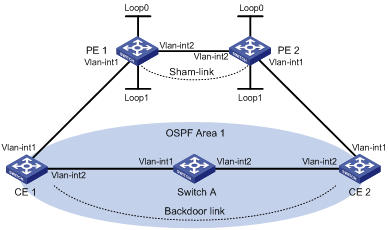
|
Interface |
IP address |
Device |
Interface |
IP address |
|
|
CE 1 |
Vlan-int1 |
100.1.1.1/24 |
CE 2 |
Vlan-int1 |
120.1.1.1/24 |
|
|
Vlan-int2 |
20.1.1.1/24 |
|
Vlan-int2 |
30.1.1.2/24 |
|
PE 1 |
Loop0 |
1.1.1.9/32 |
PE 2 |
Loop0 |
2.2.2.9/32 |
|
|
Loop1 |
3.3.3.3/32 |
|
Loop1 |
5.5.5.5/32 |
|
|
Vlan-int1 |
100.1.1.2/24 |
|
Vlan-int1 |
120.1.1.2/24 |
|
|
Vlan-int2 |
10.1.1.1/24 |
|
Vlan-int2 |
10.1.1.2/24 |
|
Switch A |
Vlan-int1 |
20.1.1.2/24 |
|
|
|
|
|
Vlan-int2 |
30.1.1.1/24 |
|
|
|
Networking and Configuration Requirements
l CE 1 and CE 2 belong to VPN 1 and are respectively connected to PE 1 and PE 2.
l CE 1 and CE 2 are in the same OSPF area.
l VPN traffic between CE 1 and CE 2 is required to be forwarded through the MPLS backbone, instead of any route in the OSPF area.
Applicable Product Matrix
|
Product series |
Software version |
Hardware version |
|
S7500E Series Ethernet Switches |
Release 6300, |
LSQ1SRP1CB SRPU(s), or exclusively EA series LPUs |
Configuration Procedure
1) Configure OSPF on the customer networks
Configure conventional OSPF on CE 1, Switch A, and CE 2 to advertise segment addresses of the interfaces as shown in Figure 3-7. The detailed configuration steps are omitted.
After completing the configurations, CE 1 and CE 2 should be able to learn the OSPF route to the VLAN interface 1 of each other. The following takes CE 1 as an example:
<CE1> display ip routing-table
Routing Tables: Public
Destinations : 9 Routes : 9
Destination/Mask Proto Pre Cost NextHop Interface
20.1.1.0/24 Direct 0 0 20.1.1.1 Vlan2
20.1.1.1/32 Direct 0 0 127.0.0.1 InLoop0
20.1.1.2/32 Direct 0 0 20.1.1.2 Vlan2
30.1.1.0/24 OSPF 10 3124 20.1.1.2 Vlan2
100.1.1.0/24 Direct 0 0 100.1.1.1 Vlan1
100.1.1.1/32 Direct 0 0 127.0.0.1 InLoop0
120.1.1.0/24 OSPF 10 3125 20.1.1.2 Vlan2
127.0.0.0/8 Direct 0 0 127.0.0.1 InLoop0
127.0.0.1/32 Direct 0 0 127.0.0.1 InLoop0
2) Configure MPLS L3VPN on the backbone
# Configure MPLS basic capability and MPLS LDP on PE 1 to establish LDP LSPs.
<PE1> system-view
[PE1] interface loopback 0
[PE1-LoopBack0] ip address 1.1.1.9 32
[PE1-LoopBack0] quit
[PE1] mpls lsr-id 1.1.1.9
[PE1] mpls
[PE1-mpls] quit
[PE1] mpls ldp
[PE1-mpls-ldp] quit
[PE1] interface vlan-interface 2
[PE1-Vlan-interface2] ip address 10.1.1.1 24
[PE1-Vlan-interface2] mpls
[PE1-Vlan-interface2] mpls ldp
[PE1-Vlan-interface2] quit
# Configure PE 1 to take PE 2 as the MP-IBGP peer.
[PE1] bgp 100
[PE1-bgp] peer 2.2.2.9 as-number 100
[PE1-bgp] peer 2.2.2.9 connect-interface loopback 0
[PE1-bgp] ipv4-family vpnv4
[PE1-bgp-af-vpnv4] peer 2.2.2.9 enable
[PE1-bgp-af-vpnv4] quit
[PE1-bgp] quit
# Configure OSPF on PE 1.
[PE1] ospf 1
[PE1-ospf-1] area 0
[PE1-ospf-1-area-0.0.0.0] network 1.1.1.9 0.0.0.0
[PE1-ospf-1-area-0.0.0.0] network 10.1.1.0 0.0.0.255
[PE1-ospf-1-area-0.0.0.0] quit
[PE1-ospf-1] quit
# Configure MPLS basic capability and MPLS LDP on PE 2 to establish LDP LSPs.
<PE2> system-view
[PE2] interface loopback 0
[PE2-LoopBack0] ip address 2.2.2.9 32
[PE2-LoopBack0] quit
[PE2] mpls lsr-id 2.2.2.9
[PE2] mpls
[PE2-mpls] quit
[PE2] mpls ldp
[PE2-mpls-ldp] quit
[PE2] interface vlan-interface 2
[PE2-Vlan-interface2] ip address 10.1.1.2 24
[PE2-Vlan-interface2] mpls
[PE2-Vlan-interface2] mpls ldp
[PE2-Vlan-interface2] quit
# Configure PE 2 to take PE 1 as the MP-IBGP peer.
[PE2] bgp 100
[PE2-bgp] peer 1.1.1.9 as-number 100
[PE2-bgp] peer 1.1.1.9 connect-interface loopback 0
[PE2-bgp] ipv4-family vpnv4
[PE2-bgp-af-vpnv4] peer 1.1.1.9 enable
[PE2-bgp-af-vpnv4] quit
[PE2-bgp] quit
# Configure OSPF on PE 2.
[PE2]ospf 1
[PE2-ospf-1]area 0
[PE2-ospf-1-area-0.0.0.0]network 2.2.2.9 0.0.0.0
[PE2-ospf-1-area-0.0.0.0]network 10.1.1.0 0.0.0.255
[PE2-ospf-1-area-0.0.0.0]quit
[PE2-ospf-1]quit
3) Configure PEs to allow CEs to access the network
# Configure PE 1 to allow CE 1 to access the network.
[PE1] ip vpn-instance vpn1
[PE1-vpn-instance-vpn1] route-distinguisher 100:1
[PE1-vpn-instance-vpn1] vpn-target 1:1
[PE1-vpn-instance-vpn1] quit
[PE1] interface vlan-interface 1
[PE1-Vlan-interface1] ip binding vpn-instance vpn1
[PE1-Vlan-interface1] ip address 100.1.1.2 24
[PE1-Vlan-interface1] quit
[PE1] ospf 100 vpn-instance vpn1
[PE1-ospf-100] domain-id 10
[PE1-ospf-100] area 1
[PE1-ospf-100-area-0.0.0.1] network 100.1.1.0 0.0.0.255
[PE1-ospf-100-area-0.0.0.1] quit
[PE1-ospf-100] quit
[PE2] bgp 100
[PE1-bgp] ipv4-family vpn-instance vpn1
[PE1-bgp-vpn1] import-route ospf 100
[PE1-bgp-vpn1] quit
[PE1-bgp] quit
# Configure PE 2 to allow CE 2 to access the network.
[PE2] ip vpn-instance vpn1
[PE2-vpn-instance-vpn1] route-distinguisher 100:2
[PE2-vpn-instance-vpn1] vpn-target 1:1
[PE2-vpn-instance-vpn1] quit
[PE2] interface vlan-interface 1
[PE2-Vlan-interface1] ip binding vpn-instance vpn1
[PE2-Vlan-interface1] ip address 120.1.1.2 24
[PE2-Vlan-interface1] quit
[PE2] ospf 100 vpn-instance vpn1
[PE2-ospf-100] domain-id 10
[PE2-ospf-100] area 1
[PE2-ospf-100-area-0.0.0.1] network 120.1.1.0 0.0.0.255
[PE2-ospf-100-area-0.0.0.1] quit
[PE2-ospf-100] quit
[PE2] bgp 100
[PE2-bgp] ipv4-family vpn-instance vpn1
[PE2-bgp-vpn1] import-route ospf 100
[PE2-bgp-vpn1] quit
[PE2-bgp] quit
After completing the above configurations, if you issue the display ip routing-table vpn-instance command on the PEs, you should see that the path to the peer CE is along the OSPF route across the customer networks, instead of the BGP route across the backbone. Take PE 1 as an example:
[PE1] display ip routing-table vpn-instance vpn1
Routing Tables: vpn1
Destinations : 5 Routes : 5
Destination/Mask Proto Pre Cost NextHop Interface
20.1.1.0/24 OSPF 10 1563 100.1.1.1 Vlan1
30.1.1.0/24 OSPF 10 3125 100.1.1.1 Vlan1
100.1.1.0/24 Direct 0 0 100.1.1.2 Vlan1
100.1.1.2/32 Direct 0 0 127.0.0.1 InLoop0
120.1.1.0/24 OSPF 10 3126 100.1.1.1 Vlan1
4) Configure a sham link
# Configure PE 1.
[PE1] interface loopback 1
[PE1-LoopBack1] ip binding vpn-instance vpn1
[PE1-LoopBack1] ip address 3.3.3.3 32
[PE1-LoopBack1] quit
[PE1] ospf 100
[PE1-ospf-100] area 1
[PE1-ospf-100-area-0.0.0.1] sham-link 3.3.3.3 5.5.5.5 cost 10
[PE1-ospf-100-area-0.0.0.1] quit
[PE1-ospf-100] quit
# Configure PE 2.
[PE2] interface loopback 1
[PE2-LoopBack1] ip binding vpn-instance vpn1
[PE2-LoopBack1] ip address 5.5.5.5 32
[PE2-LoopBack1] quit
[PE2] ospf 100
[PE2-ospf-100] area 1
[PE2-ospf-100-area-0.0.0.1] sham-link 5.5.5.5 3.3.3.3 cost 10
[PE2-ospf-100-area-0.0.0.1] quit
[PE2-ospf-100] quit
After completing the above configurations, if you issue the display ip routing-table vpn-instance command again on the PEs, you should see that the path to the peer CE is now along the BGP route across the backbone, and that a route to the sham link destination address is present. Take PE 1 as an example:
[PE1] display ip routing-table vpn-instance vpn1
Routing Tables: vpn1
Destinations : 6 Routes : 6
Destination/Mask Proto Pre Cost NextHop Interface
3.3.3.3/32 Direct 0 0 127.0.0.1 InLoop0
5.5.5.5/32 BGP 255 0 2.2.2.9 NULL0
20.1.1.0/24 OSPF 10 1563 100.1.1.1 Vlan1
100.1.1.0/24 Direct 0 0 100.1.1.2 Vlan1
100.1.1.2/32 Direct 0 0 127.0.0.1 InLoop0
120.1.1.0/24 BGP 255 0 2.2.2.9 NULL0
Issuing the display ip routing-table command on the CEs, you should see that the cost of the OSPF route to the peer CE is now 10 (the cost configured for the sham link), and that the next hop is now the VLAN interface 1 connected to the PE. This means that VPN traffic to the peer will be forwarded over the backbone. Takes CE 1 as an example:
[CE1] display ip routing-table
Routing Tables: Public
Destinations : 9 Routes : 9
Destination/Mask Proto Pre Cost NextHop Interface
20.1.1.0/24 Direct 0 0 20.1.1.1 Vlan2
20.1.1.1/32 Direct 0 0 127.0.0.1 InLoop0
20.1.1.2/32 Direct 0 0 20.1.1.2 Vlan2
30.1.1.0/24 OSPF 10 1574 100.1.1.2 Vlan1
100.1.1.0/24 Direct 0 0 100.1.1.1 Vlan1
100.1.1.1/32 Direct 0 0 127.0.0.1 InLoop0
120.1.1.0/24 OSPF 10 12 100.1.1.2 Vlan1
127.0.0.0/8 Direct 0 0 127.0.0.1 InLoop0
127.0.0.1/32 Direct 0 0 127.0.0.1 InLoop0
Issuing the display ospf sham-link command on the PEs, you should see the established sham link. Takes PE 1 as an example:
[PE1] display ospf sham-link
OSPF Process 100 with Router ID 100.1.1.2
Sham Link:
Area RouterId Source-IP Destination-IP State Cost
0.0.0.1 100.1.1.2 3.3.3.3 5.5.5.5 P-2-P 10
Issuing the display ospf sham-link area command, you should see that the status of the peer is Full:
[PE1] display ospf sham-link area 1
OSPF Process 100 with Router ID 100.1.1.2
Sham-Link: 3.3.3.3 --> 5.5.5.5
Neighbour State: Full
Area: 0.0.0.1
Cost: 10 State: P-2-P, Type: Sham
Timers: Hello 10 , Dead 40 , Retransmit 5 , Transmit Delay 1
Complete Configuration
l Configuration on PE 1
#
mpls lsr-id 1.1.1.9
#
ip vpn-instance vpn1
route-distinguisher 100:1
vpn-target 1:1 export-extcommunity
vpn-target 1:1 import-extcommunity
#
mpls
lsp-trigger all
#
mpls ldp
#
interface LoopBack0
ip address 1.1.1.9 255.255.255.255
#
interface LoopBack1
ip binding vpn-instance vpn1
ip address 3.3.3.3 255.255.255.255
#
interface Vlan-interface1
ip binding vpn-instance vpn1
ip address 100.1.1.2 255.255.255.0
#
interface Vlan-interface2
ip address 10.1.1.1 255.255.255.0
mpls
mpls ldp
#
bgp 100
undo synchronization
peer 2.2.2.9 as-number 100
peer 2.2.2.9 connect-interface LoopBack0
#
ipv4-family vpn-instance vpn1
import-route ospf 100
#
ipv4-family vpnv4
peer 2.2.2.9 enable
#
ospf 1
area 0.0.0.0
network 1.1.1.9 0.0.0.0
network 10.1.1.0 0.0.0.255
#
ospf 100 vpn-instance vpn1
domain-id 0.0.0.10
area 0.0.0.1
network 100.1.1.0 0.0.0.255
sham-link 3.3.3.3 5.5.5.5 cost 10
l Configuration on PE 2
#
mpls lsr-id 2.2.2.9
#
ip vpn-instance vpn1
route-distinguisher 100:2
vpn-target 1:1 export-extcommunity
vpn-target 1:1 import-extcommunity
#
mpls
lsp-trigger all
#
mpls ldp
#
interface LoopBack0
ip address 2.2.2.9 255.255.255.255
#
interface LoopBack1
ip binding vpn-instance vpn1
ip address 5.5.5.5 255.255.255.255
#
interface Vlan-interface1
ip binding vpn-instance vpn1
ip address 120.1.1.2 255.255.255.0
#
interface Vlan-interface2
ip address 10.1.1.2 255.255.255.0
mpls
mpls ldp
#
bgp 100
undo synchronization
peer 1.1.1.9 as-number 100
peer 1.1.1.9 connect-interface LoopBack0
#
ipv4-family vpn-instance vpn1
import-route ospf 100
#
ipv4-family vpnv4
peer 1.1.1.9 enable
#
ospf 1
area 0.0.0.0
network 2.2.2.9 0.0.0.0
network 10.1.1.0 0.0.0.255
#
ospf 100 vpn-instance vpn1
domain-id 0.0.0.10
area 0.0.0.1
network 100.1.1.0 0.0.0.255
sham-link 5.5.5.5 3.3.3.3 cost 10
![]()
On CE 1, Switch A, and CE 2, you just need to perform common OSPF configurations and advertise the network segment addresses of the interfaces as illustrated in Figure 3-7.
Configuration Guidelines
None
Configuring BGP AS Number Substitution
Network Diagram
Figure 3-8 Configure BGP AS number substitution
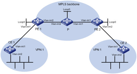
|
Interface |
IP address |
Device |
Interface |
IP address |
|
|
CE 1 |
Vlan-int1 |
10.1.1.1/24 |
P |
Loop0 |
2.2.2.9/32 |
|
|
Vlan-int2 |
100.1.1.1/24 |
|
Vlan-int1 |
30.1.1.1/24 |
|
PE 1 |
Loop0 |
1.1.1.9/32 |
|
Vlan-int2 |
20.1.1.2/24 |
|
|
Vlan-int1 |
10.1.1.2/24 |
PE 2 |
Loop0 |
3.3.3.9/32 |
|
|
Vlan-int2 |
20.1.1.1/24 |
|
Vlan-int1 |
30.1.1.2/24 |
|
CE 2 |
Vlan-int1 |
10.2.1.1/24 |
|
Vlan-int2 |
10.2.1.2/24 |
|
|
Vlan-int2 |
200.1.1.1/24 |
|
|
|
Networking and Configuration Requirements
As shown in Figure 3-8, CE 1 and CE 2 belong to VPN 1 and are connected to PE 1 and PE 2 respectively. In addition, they use the same AS number 600.
Applicable Product Matrix
|
Product series |
Software version |
Hardware version |
|
S7500E Series Ethernet Switches |
Release 6300, |
LSQ1SRP1CB SRPU(s), or exclusively EA series LPUs |
Configuration Procedure
1) Configuring basic MPLS L3VPN
l Configure OSPF on the MPLS backbone to allow the PEs and P device to learn the routes of the loopback interfaces from each other.
l Configure MPLS basic capability and MPLS LDP on the MPLS backbone to establish LDP LSPs.
l Establish MP-IBGP peer relationship between the PEs to advertise VPN IPv4 routes.
l Configure the VPN instance of VPN 1 on PE 2 to allow CE 2 to access the network.
l Configure the VPN instance of VPN 1 on PE 1 to allow CE 1 to access the network.
l Configure BGP between PE 1 and CE 1, and between PE 2 and CE 2 to inject routes of CEs into PEs.
After completing the above configurations, if you issue the display ip routing-table command on CE 2, you should see that CE 2 has learned the route to network segment 10.1.1.0/24, where the interface used by CE 1 to access PE 1 resides; but has not learned the route to the VPN (100.1.1.0/24) behind CE 1. You should see the similar situation on CE 1.
<CE2> display ip routing-table
Routing Tables: Public
Destinations : 8 Routes : 8
Destination/Mask Proto Pre Cost NextHop Interface
10.1.1.0/24 BGP 255 0 10.2.1.2 Vlan1
10.1.1.1/32 BGP 255 0 10.2.1.2 Vlan1
10.2.1.0/24 Direct 0 0 10.2.1.1 Vlan1
10.2.1.1/32 Direct 0 0 127.0.0.1 InLoop0
10.2.1.2/32 Direct 0 0 10.2.1.2 Vlan1
127.0.0.0/8 Direct 0 0 127.0.0.1 InLoop0
127.0.0.1/32 Direct 0 0 127.0.0.1 InLoop0
200.1.1.0/24 Direct 0 0 200.1.1.1 InLoop0
200.1.1.1/32 Direct 0 0 127.0.0.1 InLoop0
Issuing the display ip routing-table vpn-instance command on the PEs, you should see the route to the VPN behind the peer CE. Takes PE 2 as an example:
<PE2> display ip routing-table vpn-instance vpn1
Routing Tables: vpn1
Destinations : 7 Routes : 7
Destination/Mask Proto Pre Cost NextHop Interface
10.1.1.0/24 BGP 255 0 1.1.1.9 NULL0
10.1.1.1/32 BGP 255 0 1.1.1.9 NULL0
10.2.1.0/24 Direct 0 0 10.2.1.2 Vlan1
10.2.1.1/32 Direct 0 0 10.2.1.1 Vlan1
10.2.1.2/32 Direct 0 0 127.0.0.1 InLoop0
100.1.1.1/32 BGP 255 0 1.1.1.9 NULL0
200.1.1.1/32 BGP 255 0 10.2.1.1 Vlan1
Enabling BGP update packet debugging on PE 2, you should see that PE 2 advertises the route to 100.1.1.1/32, and the AS_PATH is 100 600.
<PE2> terminal monitor
<PE2> terminal debugging
<PE2> debugging bgp update vpn-instance vpn1 verbose
<PE2> refresh bgp vpn-instance vpn1 all export
*0.4402392 PE2 RM/7/RMDEBUG:
BGP.vpn1: Send UPDATE to 10.2.1.1 for following destinations :
Origin : Incomplete
AS Path : 100 600
Next Hop : 10.2.1.2
100.1.1.1/32,
Issuing the display bgp routing-table peer received-routes command on CE 2, you should see that CE 2 did not receive the route to 100.1.1.1/32.
<CE2> display bgp routing-table peer 10.2.1.2 received-routes
Total Number of Routes: 4
BGP Local router ID is 10.2.1.1
Status codes: * - valid, > - best, d - damped,
h - history, i - internal, s - suppressed, S - Stale
Origin : i - IGP, e - EGP, ? - incomplete
Network NextHop MED LocPrf PrefVal Path/Ogn
*> 10.1.1.0/24 10.2.1.2 0 100?
*> 10.1.1.1/32 10.2.1.2 0 100?
* 10.2.1.0/24 10.2.1.2 0 0 100?
* 10.2.1.1/32 10.2.1.2 0 0 100?
2) Configure BGP AS number substitution
# Configure BGP AS number substitution on PE 2.
<PE2> system-view
[PE2] bgp 100
[PE2-bgp] ipv4-family vpn-instance vpn1
[PE2-bgp-vpn1] peer 10.2.1.1 substitute-as
[PE2-bgp-vpn1] quit
[PE2-bgp] quit
You should see that among the routes advertised by PE 2 to CE 2, the AS_PATH of 100.1.1.1/32 has changed from 100 600 to 100 100:
*0.13498737 PE2 RM/7/RMDEBUG:
BGP.vpn1: Send UPDATE to 10.2.1.1 for following destinations :
Origin : Incomplete
AS Path : 100 100
Next Hop : 10.2.1.2
100.1.1.1/32
Display again the routing information that CE 2 receives and the routing table:
<CE2> display bgp routing-table peer 10.2.1.2 received-routes
Total Number of Routes: 5
BGP Local router ID is 10.2.1.1
Status codes: * - valid, > - best, d - damped,
h - history, i - internal, s - suppressed, S - Stale
Origin : i - IGP, e - EGP, ? - incomplete
Network NextHop MED LocPrf PrefVal Path/Ogn
*> 10.1.1.0/24 10.2.1.2 0 100?
*> 10.1.1.1/32 10.2.1.2 0 100?
* 10.2.1.0/24 10.2.1.2 0 0 100?
* 10.2.1.1/32 10.2.1.2 0 0 100?
*> 100.1.1.1/32 10.2.1.2 0 100 100?
<CE2> display ip routing-table
Routing Tables: Public
Destinations : 9 Routes : 9
Destination/Mask Proto Pre Cost NextHop Interface
10.1.1.0/24 BGP 255 0 10.2.1.2 Vlan1
10.1.1.1/32 BGP 255 0 10.2.1.2 Vlan1
10.2.1.0/24 Direct 0 0 10.2.1.1 Vlan1
10.2.1.1/32 Direct 0 0 127.0.0.1 InLoop0
10.2.1.2/32 Direct 0 0 10.2.1.2 Vlan1
100.1.1.1/32 BGP 255 0 10.2.1.2 Vlan1
127.0.0.0/8 Direct 0 0 127.0.0.1 InLoop0
127.0.0.1/32 Direct 0 0 127.0.0.1 InLoop0
200.1.1.1/32 Direct 0 0 127.0.0.1 InLoop0
After configuring BGP AS substitution on PE 1 too, the VLAN interfaces of CE 1 and CE 2 should be able to ping each other:
<CE1> ping –a 100.1.1.1 200.1.1.1
PING 200.1.1.1: 56 data bytes, press CTRL_C to break
Reply from 200.1.1.1: bytes=56 Sequence=1 ttl=253 time=109 ms
Reply from 200.1.1.1: bytes=56 Sequence=2 ttl=253 time=67 ms
Reply from 200.1.1.1: bytes=56 Sequence=3 ttl=253 time=66 ms
Reply from 200.1.1.1: bytes=56 Sequence=4 ttl=253 time=85 ms
Reply from 200.1.1.1: bytes=56 Sequence=5 ttl=253 time=70 ms
--- 200.1.1.1 ping statistics ---
5 packet(s) transmitted
5 packet(s) received
0.00% packet loss
round-trip min/avg/max = 66/79/109 ms
Complete Configuration
l Configuration on PE 1
#
mpls lsr-id 1.1.1.9
#
ip vpn-instance vpn1
route-distinguisher 100:1
vpn-target 1:1 export-extcommunity
vpn-target 1:1 import-extcommunity
#
mpls
lsp-trigger all
#
mpls ldp
#
interface LoopBack0
ip address 1.1.1.9 255.255.255.255
#
interface Vlan-interface1
ip binding vpn-instance vpn1
ip address 10.1.1.2 255.255.255.0
#
interface Vlan-interface2
ip address 20.1.1.1 255.255.255.0
mpls
mpls ldp
#
bgp 100
undo synchronization
peer 3.3.3.9 as-number 100
peer 3.3.3.9 connect-interface LoopBack0
peer 10.1.1.1 substitute-as
#
ipv4-family vpn-instance vpn1
import-route bgp 600
#
ipv4-family vpnv4
peer 3.3.3.9 enable
#
l Configuration on PE 2
#
mpls lsr-id 3.3.3.9
#
ip vpn-instance vpn1
route-distinguisher 100:1
vpn-target 1:1 export-extcommunity
vpn-target 1:1 import-extcommunity
#
mpls
lsp-trigger all
#
mpls ldp
#
interface LoopBack0
ip address 3.3.3.9 255.255.255.255
#
interface Vlan-interface1
ip address 30.1.1.2 255.255.255.0
mpls
mpls ldp
#
interface Vlan-interface2
ip binding vpn-instance vpn1
ip address 10.2.1.2 255.255.255.0
#
bgp 100
undo synchronization
peer 1.1.1.9 as-number 100
peer 1.1.1.9 connect-interface LoopBack0
peer 10.2.1.1 substitute-as
#
ipv4-family vpn-instance vpn1
import-route bgp 600
#
ipv4-family vpnv4
peer 1.1.1.9 enable
#
Configuration Guidelines
None