- Table of Contents
-
- H3C Low-End and Mid-Range Ethernet Switches Configuration Examples(V1.01)
- 00-1Cover
- 01-Login Configuration Guide
- 02-VLAN Configuration Guide
- 03-GVRP Configuration Guide
- 04-Voice VLAN Configuration Guide
- 05-IP Addressing and Performance Configuration Guide
- 06-QinQ Configuration Guide
- 07-BPDU Tunnel Configuration Guide
- 08-VLAN Mapping Configuration Guide
- 09-MAC Address Table Management Configuration Guide
- 10-Link Aggregation Configuration Guide
- 11-IP Source Guard Configuration Guide
- 12-DLDP Configuration Guide
- 13-MSTP Configuration Guide
- 14-IPv4 Routing Configuration Guide
- 15-IPv6 Configuration Guide
- 16-IPv6 Routing Configuration Guide
- 17-IPv4 Multicast Configuration Guide
- 18-IPv6 Multicast Configuration Examples
- 19-802.1x Configuration Guide
- 20-AAA Configuration Guide
- 21-MAC Authentication Configuration Guide
- 22-Portal Configuration Guide
- 23-ARP Configuration Guide
- 24-DHCP Configuration Guide
- 25-ACL Configuration Guide
- 26-QoS Configuration Guide
- 27-Port Mirroring Configuration Guide
- 28-Cluster Management Configuration Guide
- 29-SNMP-RMON Configuration Guide
- 30-NTP Configuration Guide
- 31-FTP-TFTP Configuration Guide
- 32-UDP Helper Configuration Guide
- 33-Information Center Configuration Guide
- 34-DNS Configuration Guide
- 35-File System Management Configuration Guide
- 36-Remote Upgrade Configuration Guide
- 37-NQA Configuration Guide
- 38-VRRP Configuration Guide
- 39-SSH Configuration Guide
- 40-Port Security Configuration Guide
- 41-Port Isolation Configuration Guide
- 42-LLDP Configuration Guide
- 43-MCE Configuration Guide
- 44-PoE Configuration Guide
- 45-OAM Configuration Guide
- 46-Connectivity Fault Detection Configuration Guide
- 47-RRPP Configuration Guide
- 48-sFlow Configuration Guide
- 49-SSL-HTTPS Configuration Guide
- 50-PKI Configuration Guide
- 51-Track Configuration Guide
- 52-EPON-OLT Configuration Guide
- 53-Smart Link Configuration Guide
- 54-MPLS Configuration Guide
- Related Documents
-
| Title | Size | Download |
|---|---|---|
| 47-RRPP Configuration Guide | 733.47 KB |
1 RRPP Configuration Guide (Protected VLANs Not Supported)
Configuring a Single-Ring Topology
Networking and Configuration Requirements
Configuring a Single-Domain Intersecting-Ring Topology
Networking and Configuration Requirements
Configuring a Multi-Domain Intersecting-Ring Topology
Networking and Configuration Requirements
2 RRPP Configuration Guide (Protected VLANs Supported)
Configuring a Single-Ring Topology
Networking and Configuration Requirements
Configuring a Intersecting-Ring Topology
Networking and Configuration Requirements
Configuring Intersecting-Ring Load Balancing
Networking and Configuration Requirements
1 RRPP Configuration Guide (Protected VLANs Not Supported)
Configuring a Single-Ring Topology
Rapid Ring Protection Protocol (RRPP) is an Ethernet ring-specific link layer protocol. It can not only prevent data loop from causing broadcast storm efficiently when the Ethernet ring is complete, but also restore communication channels among nodes on the Ethernet ring rapidly when a link is torn down. Compared with Spanning Tree Protocol (STP), RRPP features:
l Expedited topology convergence
l Independent of the number of nodes on the Ethernet ring
Network Diagram
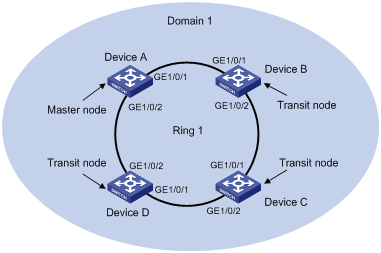
Figure 1-1 A single-ring topology networking diagram
Networking and Configuration Requirements
l Device A, Device B, Device C and Device D constitute RRPP domain 1.
l VLAN 4092 is the control VLAN of RRPP domain 1.
l Device A, Device B, Device C and Device D constitute primary ring 1.
l Device A is the master node of primary ring 1, GigabitEthernet 1/0/1 is the primary port and GigabitEthernet 1/0/2 is the secondary port.
l The timer of the primary ring adopts the default value.
Applicable Product Matrix
|
Product series |
Software version |
Hardware version |
|
S3610 series Ethernet switches |
Release 5301, Release 5303 |
All versions |
|
S5510 series Ethernet switches |
Release 5301, Release 5303 |
All versions |
|
S5500-EI series Ethernet switches |
Release 2102 |
All versions |
|
S7500E series Ethernet switches |
Release 6100 |
All versions |
Configuration Procedure
![]()
l The following describes the configurations on Device A (master node) and Device B (transit node) only. The configuration on Device C and on Device D is the same as that on Device B.
l You must configure the ports accessing an RRPP ring as trunk ports, permitting the traffic of data VLANs to pass through. For details, refer to Ethernet Interface Configuration Guide in this manual.
l You must disable STP on ports accessing RRPP rings.
1) Configuration on Switch A
# Create an RRPP domain on Device A and specify a control VLAN.
<DeviceA> system-view
[DeviceA] rrpp domain 1
[DeviceA-rrpp-domain1] control-vlan 4092
# Configure Device A as the master node of the primary ring. Specify GigabitEthernet 1/0/1 and GigabitEthernet 1/0/2 of Device A as the primary port and the secondary port that access the primary ring.
[DeviceA-rrpp-domain1] ring 1 node-mode master primary-port gigabitethernet 1/0/1 secondary-port gigabitethernet 1/0/2 level 0
# Enable the RRPP ring.
[DeviceA-rrpp-domain1] ring 1 enable
[DeviceA-rrpp-domain1] quit
# Enable RRPP.
[DeviceA] rrpp enable
2) Configuration on Switch B
# Create an RRPP domain on Device B and specify a control VLAN, using the same domain ID and control VLAN as other nodes in the domain.
<DeviceB> system-view
[DeviceB] rrpp domain 1
[DeviceB-rrpp-domain1] control-vlan 4092
# Configure Device B as the transit node of the primary ring. Specify GigabitEthernet 1/0/1 and GigabitEthernet 1/0/2 of Device B as the primary port and the secondary port that access the primary ring.
[DeviceB-rrpp-domain1] ring 1 node-mode transit primary-port gigabitethernet 1/0/1 secondary-port gigabitethernet 1/0/2 level 0
# Enable the RRPP ring.
[DeviceB-rrpp-domain1] ring 1 enable
[DeviceB-rrpp-domain1] quit
# Enable RRPP.
[DeviceB] rrpp enable
Complete Configuration
l Configuration on Switch A
#
rrpp domain 1
control-vlan 4092
ring 1 node-mode master primary-port GigabitEthernet1/0/1 secondary-port GigabitEthernet1/0/2 level 0
ring 1 enable
#
rrpp enable
#
l Configuration on Switch B
#
rrpp domain 1
control-vlan 4092
ring 1 node-mode transit primary-port GigabitEthernet1/0/1 secondary-port GigabitEthernet1/0/2 level 0
ring 1 enable
#
rrpp enable
#
Configuration Guidelines
l RRPP does not have an auto election mechanism, so you must configure each node in the ring network properly for RRPP to monitor and protect the ring network.
l Before configuring RRPP, you need to construct a ring-shaped Ethernet topology physically.
l Control VLAN configuration is required for configuring an RRPP ring.
l The control VLAN configured for an RRPP domain must be a new one.
l You can only configure a control VLAN for the primary ring (namely the primary control VLAN). However, the control VLAN of a subring (namely the secondary control VLAN) is assigned automatically by the system and its VLAN ID is the control VLAN of the primary ring plus 1. Therefore, you must use two new continuous VLANs when configuring a control VLAN. Otherwise, the configuration fails.
l Each RRPP domain is bound to a control VLAN only. You will remove a control VLAN when removing an RRPP domain. However, you cannot use the undo vlan all command to remove a control VLAN.
l You cannot specify a control VLAN as a remote mirroring VLAN or an isolate-user-VLAN.
l Do not enable QinQ or VLAN mapping on the control VLAN. Otherwise, RRPPDUs cannot be forwarded properly.
l Do not configure the default VLAN of a port accessing an RRPP ring as the primary control VLAN or the secondary control VLAN, ensuring proper receiving/sending of RRPP packets.
l Modification of node mode, port role and ring level of an RRPP ring is prohibited after configuration. If needed, you must first delete the existing configuration.
l To use the undo rrpp domain command to remove an RRPP domain, you must ensure the RRPP domain has no RRPP ring.
l You must configure the ports accessing an RRPP ring as trunk ports, permitting the traffic of data VLANs to pass through.
l Ports accessing an RRPP ring must not be aggregate ports or service loop ports.
l You must not enable STP, 802.1x, MAC address authentication, voice VLAN or smart link on ports accessing an RRPP ring.
l Do not enable OAM remote loopback function on an RRPP port. Otherwise, this may cause temporary broadcast storm.
l Enable link status rapid report function on a port accessing an RRPP ring (the link-delay of the port is set to 0) to accelerate topology convergence.
l If you need to transparently transmit RRPP packets on a device without enabling RRPP, you must ensure that only the two ports accessing an RRPP ring permit the packets of the control VLAN. Otherwise, the packets from other VLANs may go into the control VLAN in transparent transmission mode and strike the RRPP ring.
Configuring a Single-Domain Intersecting-Ring Topology
Network Diagram
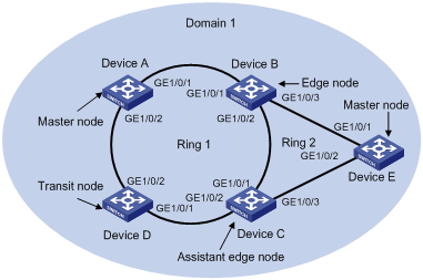
Figure 1-2 A single-domain intersecting ring topology networking diagram
Networking and Configuration Requirements
l Device A, Device B, Device C, Device D and Device E constitute RRPP domain 1.
l VLAN 4092 is the control VLAN of RRPP domain 1.
l Device A, Device B, Device C and Device D constitute primary ring 1.
l Device B, Device C and Device E constitute subring 2.
l Device A is the master node of primary ring 1, GigabitEthernet 1/0/1 is the primary port, and GigabitEthernet 1/0/2 is the secondary port.
l Device E is the master node of subring 1, GigabitEthernet 1/0/1 is the primary port, and GigabitEthernet 1/0/2 is the secondary port.
l Device B is the transit node of primary ring 1 and the edge node of subring 2, GigabitEthernet 1/0/2 is the common port, and GigabitEthernet 1/0/3 is the edge port.
l Device C is the transit node of primary ring 1 and the assistant edge node of subring 1, GigabitEthernet 1/0/1 is the common port, and GigabitEthernet 1/0/3 is the edge port.
l Device D is the transit node of primary ring 1, GigabitEthernet 1/0/1 is the primary port, and GigabitEthernet 1/0/2 is the secondary port.
l The timers of both the primary ring and the subring adopt the default value.
Applicable Product Matrix
|
Product series |
Software version |
Hardware version |
|
S3610 series Ethernet switches |
Release 5301, Release 5303 |
All versions |
|
S5510 series Ethernet switches |
Release 5301, Release 5303 |
All versions |
|
S5500-EI series Ethernet switches |
Release 2102 |
All versions |
|
S7500E series Ethernet switches |
Release 6100 |
All versions |
Configuration Procedure
![]()
l You must configure the ports accessing an RRPP ring as trunk ports, permitting the traffic of data VLANs to pass through. For details, refer to Ethernet Interface Configuration Guide in this manual.
l Disable STP on ports accessing RRPP rings.
1) Configuration on Switch A
# Create an RRPP domain on Device A and specify a control VLAN.
<DeviceA> system-view
[DeviceA] rrpp domain 1
[DeviceA-rrpp-domain1] control-vlan 4092
# Configure Device A as the master node of the primary ring. Specify GigabitEthernet 1/0/1 and GigabitEthernet 1/0/2 of Device A as the primary port and the secondary port that access the primary ring.
[DeviceA-rrpp-domain1] ring 1 node-mode master primary-port gigabitethernet 1/0/1 secondary-port gigabitethernet 1/0/2 level 0
# Enable the RRPP ring.
[DeviceA-rrpp-domain1] ring 1 enable
[DeviceA-rrpp-domain1] quit
# Enable RRPP.
[DeviceA] rrpp enable
2) Configuration on Switch B
# Create an RRPP domain on Device B and specify a control VLAN, using the same domain ID and control VLAN as other nodes in the domain.
<DeviceB> system-view
[DeviceB] rrpp domain 1
[DeviceB-rrpp-domain1] control-vlan 4092
# Configure Device B as the transit node of the primary ring. Specify GigabitEthernet 1/0/1 and GigabitEthernet 1/0/2 of Device B as the primary port and the secondary port that access the primary ring.
[DeviceB-rrpp-domain1] ring 1 node-mode transit primary-port gigabitethernet 1/0/1 secondary-port gigabitethernet 1/0/2 level 0
# Configure Device B as the edge node of the subring. Specify GigabitEthernet 1/0/2 and GigabitEthernet 1/0/3 of Device B as the common port and the edge port that access the subring. You do not need to configure the level values when using the ring command to configure an edge node.
[DeviceB-rrpp-domain1] ring 2 node-mode edge common-port gigabitethernet 1/0/2 edge-port gigabitethernet 1/0/3
# Enable the RRPP ring and RRPP subring.
[DeviceB-rrpp-domain1] ring 1 enable
[DeviceB-rrpp-domain1] ring 2 enable
[DeviceB-rrpp-domain1] quit
# Enable RRPP.
[DeviceB] rrpp enable
3) Configuration on Switch C
# Create an RRPP domain on Device C and specify a control VLAN, using the same domain ID and control VLAN as other nodes in the domain.
<DeviceC> system-view
[DeviceC] rrpp domain 1
[DeviceC-rrpp-domain1] control-vlan 4092
# Configure Device C as the transit node of the primary ring. Specify GigabitEthernet 1/0/1 and GigabitEthernet 1/0/2 of Device C as the primary port and the secondary port that access the primary ring.
[DeviceC-rrpp-domain1] ring 1 node-mode transit primary-port gigabitethernet 1/0/1 secondary-port gigabitethernet 1/0/2 level 0
# Configure Device C as the assistant-edge edge node of the subring. Specify GigabitEthernet 1/0/1 and GigabitEthernet 1/0/3 of Device C as the common port and the edge port that access the subring. You do not need to configure the level values when using the ring command to configure an assistant edge node.
[DeviceC-rrpp-domain1] ring 2 node-mode assistant-edge common-port gigabitethernet 1/0/1 edge-port gigabitethernet 1/0/3
# Enable the RRPP ring and RRPP subring.
[DeviceC-rrpp-domain1] ring 1 enable
[DeviceC-rrpp-domain1] ring 2 enable
[DeviceC-rrpp-domain1] quit
# Enable RRPP.
[DeviceC] rrpp enable
4) Configuration on Switch D
# Create an RRPP domain on Device D and specify a control VLAN, using the same domain ID and control VLAN as other nodes in the domain.
<DeviceD> system-view
[DeviceD] rrpp domain 1
[DeviceD-rrpp-domain1] control-vlan 4092
# Configure Device D as the transit node of the primary ring. Specify GigabitEthernet 1/0/1 and GigabitEthernet 1/0/2 of Device D as the primary port and the secondary port that access the primary ring.
[DeviceD-rrpp-domain1] ring 1 node-mode transit primary-port gigabitethernet 1/0/1 secondary-port gigabitethernet 1/0/2 level 0
# Enable the RRPP ring.
[DeviceD-rrpp-domain1] ring 1 enable
[DeviceD-rrpp-domain1] quit
# Enable RRPP.
[DeviceD] rrpp enable
5) Configuration on Switch E
# Create an RRPP domain on Device E and specify a control VLAN, using the same domain ID and control VLAN as other nodes in the domain.
<DeviceE> system-view
[DeviceE] rrpp domain 1
[DeviceE-rrpp-domain1] control-vlan 4092
# Configure Device E as the master node of the subring. Specify GigabitEthernet 1/0/1 and GigabitEthernet 1/0/2 of Device E as the primary port and the secondary port that access the subring.
[DeviceE-rrpp-domain1] ring 2 node-mode master primary-port gigabitethernet 1/0/1 secondary-port gigabitethernet 1/0/2 level 1
# Enable the RRPP subring.
[DeviceE-rrpp-domain1] ring 2 enable
[DeviceE-rrpp-domain1] quit
# Enable RRPP.
[DeviceE] rrpp enable
Complete Configuration
l Configuration on Switch A
#
rrpp domain 1
control-vlan 4092
ring 1 node-mode master primary-port GigabitEthernet1/0/1 secondary-port GigabitEthernet1/0/2 level 0
ring 1 enable
#
rrpp enable
#
l Configuration on Switch B
#
rrpp domain 1
control-vlan 4092
ring 1 node-mode transit primary-port GigabitEthernet1/0/1 secondary-port GigabitEthernet1/0/2 level 0
ring 2 node-mode edge common-port GigabitEthernet1/0/2 edge-port GigabitEthernet1/0/3
ring 1 enable
ring 2 enable
#
rrpp enable
#
l Configuration on Switch C
#
rrpp domain 1
control-vlan 4092
ring 1 node-mode transit primary-port GigabitEthernet1/0/1 secondary-port GigabitEthernet1/0/2 level 0
ring 2 node-mode assistant-edge common-port GigabitEthernet1/0/1 edge-port GigabitEthernet1/0/3
ring 1 enable
ring 2 enable
#
rrpp enable
#
l Configuration on Switch D
#
rrpp domain 1
control-vlan 4092
ring 1 node-mode transit primary-port GigabitEthernet1/0/1 secondary-port GigabitEthernet1/0/2 level 0
ring 1 enable
#
rrpp enable
#
l Configuration on Switch E
#
rrpp domain 1
control-vlan 4092
ring 2 node-mode master primary-port GigabitEthernet1/0/1 secondary-port GigabitEthernet1/0/2 level 1
ring 2 enable
#
rrpp enable
#
Configuration Guidelines
In addition to the precautions in Configuration Guidelines in Configuring a Single-Ring Topology, make sure that:
l You must first configure the primary ring and then the subring when configuring an RRPP domain. In addition, different RRPP rings in the same RRPP domain cannot share the same ring ID.
l If a device is on multiple RRPP rings in the same RRPP domain, only one primary ring exists. Moreover, the node role of the device on other subrings can be either edge node or assistant edge node only.
l You do not need to configure the level values when using the ring command to configure an edge node or an assistant edge node.
l The total number of rings configured on a device in all RRPP domains cannot be greater than 16.
l Do not configure the default VLAN of a port accessing an RRPP ring as the primary control VLAN or the secondary control VLAN (the secondary control VLAN is the control VLAN plus 1), ensuring proper receiving/sending of RRPP packets.
l You must first configure the primary ring and then the subring when configuring an edge node or an assistant edge node. Moreover, you must remove all subring configurations before deleting the primary ring configuration of an edge node. However, the RRPP ring enabled cannot be deleted.
Configuring a Multi-Domain Intersecting-Ring Topology
Network Diagram
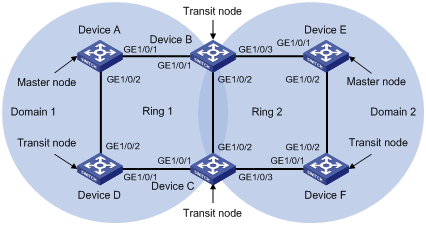
Figure 1-3 A multi-domain intersecting ring topology networking diagram
Networking and Configuration Requirements
l Device A, Device B, Device C and Device D constitute RRPP domain 1; Device E, Device F, Device C and Device B constitute RRPP domain 2.
l VLAN 4090 is the control VLAN of RRPP domain 1, and VLAN 4092 is the control VLAN of RRPP domain 2.
l Device A, Device B, Device C and Device D constitute primary ring 1.
l Device E, Device F, Device C and Device B constitute primary ring 2.
l Device A is the master node of primary ring 1 in RRPP domain 1, GigabitEthernet 1/0/1 is the primary port, and GigabitEthernet 1/0/2 is the secondary port.
l Device E is the master node of primary ring 2 in RRPP domain 2, GigabitEthernet 1/0/1 is the primary port, and GigabitEthernet 1/0/2 is the secondary port.
l Device B is both the transit node of primary ring 1 in RRPP domain 1 and the transit node of primary ring 2 in RRPP domain 2. GigabitEthernet 1/0/2 is the multi-domain intersecting common port.
l Device C is both the transit node of primary ring 1 in RRPP domain 1 and the transit node of primary ring 2 in RRPP domain 2. GigabitEthernet 1/0/2 is the multi-domain intersecting common port.
l Device D is the transit node of primary ring 1 in RRPP domain 1, GigabitEthernet 1/0/1 is the primary port, and GigabitEthernet 1/0/2 is the secondary port.
l Device F is the transit node of primary ring 2 in RRPP domain 2, GigabitEthernet 1/0/1 is the primary port and GigabitEthernet 1/0/2 is the secondary port.
l The timers of primary rings in both domains adopt the default values.
Applicable Product Matrix
|
Product series |
Software version |
Hardware version |
|
S3610 series Ethernet switches |
Release 5301, Release 5303 |
All versions |
|
S5510 series Ethernet switches |
Release 5301, Release 5303 |
All versions |
|
S5500-EI series Ethernet switches |
Release 2102 |
All versions |
Configuration Procedure
![]()
l The rings within different domains are independent when you configure multi-domain intersecting rings. Data VLANs in different domains must be isolated from each other.
l You must configure the ports in all domains accessing an RRPP ring as trunk ports, permitting the traffic of data VLANs to pass through. For details, refer to Ethernet Interface Configuration Guide in this manual.
l Disable STP on ports accessing RRPP rings.
1) Configuration on Switch A
# Create RRPP domain 1 on Device A and specify a control VLAN.
<DeviceA> system-view
[DeviceA] rrpp domain 1
[DeviceA-rrpp-domain1] control-vlan 4090
# Configure Device A as the master node of the primary ring. Specify GigabitEthernet 1/0/1 and GigabitEthernet 1/0/2 of Device A as the primary port and the secondary port that access the primary ring.
[DeviceA-rrpp-domain1] ring 1 node-mode master primary-port gigabitethernet 1/0/1 secondary-port gigabitethernet 1/0/2 level 0
# Enable the RRPP ring.
[DeviceA-rrpp-domain1] ring 1 enable
[DeviceA-rrpp-domain1] quit
# Enable RRPP.
[DeviceA] rrpp enable
2) Configuration on Switch B
# Create RRPP domain 1 on Device B and specify a control VLAN, using the same domain ID and control VLAN as other nodes in domain 1.
<DeviceB> system-view
[DeviceB] rrpp domain 1
[DeviceB-rrpp-domain1] control-vlan 4090
# Configure Device B as the transit node of the primary ring 1 in domain 1. Specify GigabitEthernet 1/0/1 and GigabitEthernet 1/0/2 of Device B as the primary port and the secondary port that access primary ring 1.
[DeviceB-rrpp-domain1] ring 1 node-mode transit primary-port gigabitethernet 1/0/1 secondary-port gigabitethernet 1/0/2 level 0
# Enable RRPP ring 1.
[DeviceB-rrpp-domain1] ring 1 enable
[DeviceB-rrpp-domain1] quit
# Create RRPP domain 2 on Device B and specify a control VLAN, using the same domain ID and control VLAN as other nodes in domain 2.
[DeviceB] rrpp domain 2
[DeviceB-rrpp-domain2] control-vlan 4092
# Configure Device B as the transit node of the primary ring in domain 2. Specify GigabitEthernet 1/0/2 and GigabitEthernet 1/0/3 of Device B as the primary port and the secondary port that access primary ring 2.
[DeviceB-rrpp-domain2] ring 2 node-mode transit primary-port gigabitethernet 1/0/2 secondary-port gigabitethernet 1/0/3 level 0
# Enable RRPP ring 2.
[DeviceB-rrpp-domain2] ring 2 enable
[DeviceB-rrpp-domain2] quit
# Enable RRPP.
[DeviceB] rrpp enable
3) Configuration on Switch C
# Create RRPP domain 1 on Device C and specify a control VLAN, using the same domain ID and control VLAN as other nodes in domain 1.
<DeviceC> system-view
[DeviceC] rrpp domain 1
[DeviceC-rrpp-domain1] control-vlan 4090
# Configure Device C as the transit node of primary ring 1. Specify GigabitEthernet 1/0/1 and GigabitEthernet 1/0/2 of Device C as the primary port and the secondary port that access primary ring 1.
[DeviceC-rrpp-domain1] ring 1 node-mode transit primary-port gigabitethernet 1/0/1 secondary-port gigabitethernet 1/0/2 level 0
# Enable RRPP ring 1.
[DeviceC-rrpp-domain1] ring 1 enable
[DeviceC-rrpp-domain1] quit
# Create RRPP domain 2 on Device C and specify a control VLAN, using the same domain ID and control VLAN as other nodes in domain 2.
[DeviceC] rrpp domain 2
[DeviceC-rrpp-domain2] control-vlan 4092
# Configure Device C as the transit node of primary ring 2 in domain 2. Specify GigabitEthernet 1/0/3 and GigabitEthernet 1/0/2 of Device C as the primary port and the secondary port that access primary ring 2.
[DeviceC-rrpp-domain2] ring 2 node-mode transit primary-port gigabitethernet 1/0/3 secondary-port gigabitethernet 1/0/2 level 0
# Enable RRPP ring 2.
[DeviceC-rrpp-domain2] ring 2 enable
[DeviceC-rrpp-domain2] quit
# Enable RRPP.
[DeviceC] rrpp enable
4) Configuration on Switch D
# Create RRPP domain 1 on Device D and specify a control VLAN, using the same domain ID and control VLAN as other nodes in domain 1.
<DeviceD> system-view
[DeviceD] rrpp domain 1
[DeviceD-rrpp-domain1] control-vlan 4090
# Configure Device D as the transit node of primary ring 1 in domain 1. Specify GigabitEthernet 1/0/1 and GigabitEthernet 1/0/2 of Device D as the primary port and the secondary port that access primary ring 1.
[DeviceD-rrpp-domain1] ring 1 node-mode transit primary-port gigabitethernet 1/0/1 secondary-port gigabitethernet 1/0/2 level 0
# Enable RRPP ring 1.
[DeviceD-rrpp-domain1] ring 1 enable
[DeviceD-rrpp-domain1] quit
# Enable RRPP.
[DeviceD] rrpp enable
5) Configuration on Switch E
# Create RRPP domain 2 on Device E and specify a control VLAN, using the same domain ID and control VLAN as other nodes in domain 2.
<DeviceE> system-view
[DeviceE] rrpp domain 2
[DeviceE-rrpp-domain2] control-vlan 4092
# Configure Device E as the master node of primary ring 2 in domain 2. Specify GigabitEthernet 1/0/1 and GigabitEthernet 1/0/2 of Device E as the primary port and the secondary port that access primary ring 2.
[DeviceE-rrpp-domain2] ring 2 node-mode master primary-port gigabitethernet 1/0/1 secondary-port gigabitethernet 1/0/2 level 0
# Enable RRPP ring 2.
[DeviceE-rrpp-domain2] ring 2 enable
[DeviceE-rrpp-domain2] quit
# Enable RRPP.
[DeviceE] rrpp enable
6) Configuration on Switch F
# Create RRPP domain 2 on Device F and specify a control VLAN, using the same domain ID and control VLAN as other nodes in domain 2.
<DeviceF> system-view
[DeviceF] rrpp domain 2
[DeviceF-rrpp-domain2] control-vlan 4092
# Configure Device F as the transit node of primary ring 2 in domain 2. Specify GigabitEthernet 1/0/1 and GigabitEthernet 1/0/2 of Device F as the primary port and the secondary port that access primary ring 2.
[DeviceF-rrpp-domain2] ring 2 node-mode transit primary-port gigabitethernet 1/0/1 secondary-port gigabitethernet 1/0/2 level 0
# Enable RRPP ring 2.
[DeviceF-rrpp-domain2] ring 2 enable
[DeviceF-rrpp-domain2] quit
# Enable RRPP.
[DeviceF] rrpp enable
Complete Configuration
l Configuration on Switch A
#
rrpp domain 1
control-vlan 4090
ring 1 node-mode master primary-port GigabitEthernet1/0/1 secondary-port GigabitEthernet1/0/2 level 0
ring 1 enable
#
rrpp enable
#
l Configuration on Switch B
#
rrpp domain 1
control-vlan 4090
ring 1 node-mode transit primary-port GigabitEthernet1/0/1 secondary-port GigabitEthernet1/0/2 level 0
ring 1 enable
#
rrpp domain 2
control-vlan 4092
ring 2 node-mode transit primary-port GigabitEthernet1/0/2 secondary-port GigabitEthernet1/0/3 level 0
ring 2 enable
#
rrpp enable
#
l Configuration on Switch C
#
rrpp domain 1
control-vlan 4090
ring 1 node-mode transit primary-port GigabitEthernet1/0/1 secondary-port GigabitEthernet1/0/2 level 0
ring 1 enable
#
rrpp domain 2
control-vlan 4092
ring 2 node-mode transit primary-port GigabitEthernet1/0/3 secondary-port GigabitEthernet1/0/2 level 0
ring 2 enable
#
rrpp enable
#
l Configuration on Switch D
#
rrpp domain 1
control-vlan 4090
ring 1 node-mode transit primary-port GigabitEthernet1/0/1 secondary-port GigabitEthernet1/0/2 level 0
ring 1 enable
#
rrpp enable
#
l Configuration on Switch E
#
rrpp domain 2
control-vlan 4092
ring 2 node-mode master primary-port GigabitEthernet1/0/1 secondary-port GigabitEthernet1/0/2 level 0
ring 2 enable
#
rrpp enable
#
l Configuration on Switch F
#
rrpp domain 2
control-vlan 4092
ring 2 node-mode transit primary-port GigabitEthernet1/0/1 secondary-port GigabitEthernet1/0/2 level 0
ring 2 enable
#
rrpp enable
#
Configuration Guidelines
In addition to the precautions in Configuration Guidelines of Configuring a Single-Domain Intersecting-Ring Topology, make sure that:
l Multi-domain intersecting rings must have their primary rings intersected. In another word, you cannot configure a port on a subring node as a multi-domain intersecting common port.
l You cannot configure the secondary port on the master node as the common port of the multi-domain intersecting rings when it is blocked.
l You cannot configure a node’s two ports accessing the same RRPP ring as the multi-domain intersecting common ports simultaneously.
l With RRPP enabled globally, you cannot enable or disable the RRPP rings on which the multi-domain intersecting common port resides when configuring multi-domain intersecting rings.
l The rings within different domains are independent when you configure multi-domain intersecting rings. Data VLANs in different domains must be isolated from each other.
![]()
To be compatible with old-version RRPP, which does not support protected VLAN configuration, an RRPP domain protects all VLANs on a device started with an old-version configuration file.
Configuring a Single-Ring Topology
Rapid Ring Protection Protocol (RRPP) is an Ethernet ring-specific link layer protocol. It can not only prevent data loop from causing broadcast storm efficiently when the Ethernet ring is complete, but also restore communication channels among nodes on the Ethernet ring rapidly when a link is torn down. Compared with Spanning Tree Protocol (STP), RRPP features:
l Expedited topology convergence
l Independent of the number of nodes on the Ethernet ring
Network Diagram
Figure 2-1 A single-ring topology networking diagram
Networking and Configuration Requirements
l Device A, Device B, Device C and Device D constitute RRPP domain 1.
l VLAN 4092 is the control VLAN of RRPP domain 1.
l RPPP domain 1 protects all VLANs.
l Device A, Device B, Device C and Device D constitute primary ring 1.
l Device A is the master node of primary ring 1, GigabitEthernet 1/0/1 is the primary port and GigabitEthernet 1/0/2 is the secondary port.
l Device B, Device C and Device D are the transit nodes of primary ring 1, and their GigabitEthernet 1/0/1 is the primary port and GigabitEthernet 1/0/2 is the secondary port.
l The timer of the primary ring adopts the default value.
Applicable Product Matrix
|
Product series |
Software version |
Hardware version |
|
S7500E series Ethernet switches |
Release 6300 |
All versions |
Configuration Procedure
![]()
l The following describes the configurations on Device A (master node) and Device B (transit node) only. The configuration on Device C and on Device D is the same as that on Device B.
l You must configure the ports accessing an RRPP ring as trunk ports, permitting the traffic of data VLANs to pass through. For details, refer to Ethernet Interface Configuration Guide in this manual.
l You must disable STP on ports accessing RRPP rings.
1) Configuration on Switch A
# Create an RRPP domain on Device A and specify a control VLAN.
<DeviceA> system-view
[DeviceA] rrpp domain 1
[DeviceA-rrpp-domain1] control-vlan 4092
# Configure the MSTIs referenced by the protected VLANs. The MSTI range depends on the device model. In this example, the MSTI ID ranges from 0 to 31.
[DeviceA-rrpp-domain1] protected-vlan reference-instance 0 to 31
# Configure Device A as the master node of the primary ring. Specify GigabitEthernet 1/0/1 and GigabitEthernet 1/0/2 of Device A as the primary port and the secondary port that access the primary ring.
[DeviceA-rrpp-domain1] ring 1 node-mode master primary-port gigabitethernet 1/0/1 secondary-port gigabitethernet 1/0/2 level 0
# Enable the RRPP ring.
[DeviceA-rrpp-domain1] ring 1 enable
[DeviceA-rrpp-domain1] quit
# Enable RRPP.
[DeviceA] rrpp enable
2) Configuration on Switch B
# Create an RRPP domain on Device B and specify a control VLAN, using the same domain ID and control VLAN as other nodes in the domain.
<DeviceB> system-view
[DeviceB] rrpp domain 1
[DeviceB-rrpp-domain1] control-vlan 4092
# Configure the MSTIs referenced by the protected VLANs. The MSTI range depends on the device model. In this example, the MSTI ID ranges from 0 to 31.
[DeviceB-rrpp-domain1] protected-vlan reference-instance 0 to 31
# Configure Device B as the transit node of the primary ring. Specify GigabitEthernet 1/0/1 and GigabitEthernet 1/0/2 of Device B as the primary port and the secondary port that access the primary ring.
[DeviceB-rrpp-domain1] ring 1 node-mode transit primary-port gigabitethernet 1/0/1 secondary-port gigabitethernet 1/0/2 level 0
# Enable the RRPP ring.
[DeviceB-rrpp-domain1] ring 1 enable
[DeviceB-rrpp-domain1] quit
# Enable RRPP.
[DeviceB] rrpp enable
After the above configuration, you can use the display command to view RRPP configuration.
Complete Configuration
l Configuration on Switch A
#
rrpp domain 1
control-vlan 4092
protected-vlan reference-instance 0 to 31
ring 1 node-mode master primary-port GigabitEthernet1/0/1 secondary-port GigabitEthernet1/0/2 level 0
ring 1 enable
#
rrpp enable
#
l Configuration on Switch B
#
rrpp domain 1
control-vlan 4092
protected-vlan reference-instance 0 to 31
ring 1 node-mode transit primary-port GigabitEthernet1/0/1 secondary-port GigabitEthernet1/0/2 level 0
ring 1 enable
#
rrpp enable
#
Configuration Guidelines
l RRPP does not have an auto election mechanism, so you must configure each node in the ring network properly for RRPP to monitor and protect the ring network.
l Before configuring RRPP, you need to construct a ring-shaped Ethernet topology physically.
l Before configuring rings for an RRPP domain, you must configure protected VLANs and protected VLANs for the domain first.
l The control VLAN configured for an RRPP domain must be a new one.
l You can only configure a control VLAN for the primary ring (namely the primary control VLAN). However, the control VLAN of a subring (namely the secondary control VLAN) is assigned automatically by the system and its VLAN ID is the control VLAN of the primary ring plus 1. Therefore, you must use two new continuous VLANs when configuring a control VLAN. Otherwise, the configuration fails.
l Each RRPP domain is bound to a control VLAN only. You will remove a control VLAN when removing an RRPP domain. However, you cannot use the undo vlan all command to remove a control VLAN.
l You cannot specify a control VLAN as a remote mirroring VLAN or an isolate-user-VLAN.
l Do not enable QinQ or VLAN mapping on the control VLAN. Otherwise, RRPPDUs cannot be forwarded properly.
l Do not configure the default VLAN of a port accessing an RRPP ring as the primary control VLAN or the secondary control VLAN, ensuring proper receiving/sending of RRPP packets.
l Protected VLAN configuration is required for configuring an RRPP ring. After specifying rings for an RRPP domain, you can delete or modify the protected VLANs configured for the RRPP domain, however, you cannot delete all the protected VLANs configured for the domain.
l The protected-vlan command configures protected VLANs for an RRPP domain by referencing MSTIs to which the protected VLANs are mapped. When the VLAN-to-MSTI mappings change, the protected VLANs of an RRPP domain also changes according to the MSTIs configured for the domain.
l All the VLANs permitted to pass through RRPP ports must be configured as protected VLANs of the RRPP domain.
l To activate the RRPP domain, RRPP protocol and the RRPP ring must be enabled simultaneously.
l Modification of node mode, port role and ring level of an RRPP ring is prohibited after configuration. If needed, you must first delete the existing configuration.
l To use the undo rrpp domain command to remove an RRPP domain, you must ensure the RRPP domain has no RRPP ring.
l You must configure the ports accessing an RRPP ring as trunk ports, permitting the traffic of data VLANs to pass through.
l Ports accessing an RRPP ring must not be member ports of any aggregation group, service loopback group, or smart link group.
l You must not enable STP, 802.1x, MAC address authentication, voice VLAN or smart link on ports accessing an RRPP ring.
l Do not enable OAM remote loopback function on an RRPP port. Otherwise, this may cause temporary broadcast storm.
l Enable link status rapid report function on a port accessing an RRPP ring (the link-delay of the port is set to 0) to accelerate topology convergence.
l If you need to transparently transmit RRPP packets on a device without enabling RRPP, you must ensure that only the two ports accessing an RRPP ring permit the packets of the control VLAN. Otherwise, the packets from other VLANs may go into the control VLAN in transparent transmission mode and strike the RRPP ring.
Configuring a Intersecting-Ring Topology
Network Diagram
Figure 2-2 A intersecting ring topology networking diagram
Networking and Configuration Requirements
l Device A, Device B, Device C, Device D and Device E constitute RRPP domain 1.
l VLAN 4092 is the control VLAN of RRPP domain 1.
l RPPP domain 1 protects all VLANs;
l Device A, Device B, Device C and Device D constitute primary ring 1.
l Device B, Device C and Device E constitute subring 2.
l Device A is the master node of primary ring 1, GigabitEthernet 1/0/1 is the primary port, and GigabitEthernet 1/0/2 is the secondary port.
l Device E is the master node of subring 1, GigabitEthernet 1/0/1 is the primary port, and GigabitEthernet 1/0/2 is the secondary port.
l Device B is the transit node of primary ring 1 and the edge node of subring 2, GigabitEthernet 1/0/2 is the common port, and GigabitEthernet 1/0/3 is the edge port.
l Device C is the transit node of primary ring 1 and the assistant edge node of subring 1, GigabitEthernet 1/0/1 is the common port, and GigabitEthernet 1/0/3 is the edge port.
l Device D is the transit node of primary ring 1, GigabitEthernet 1/0/1 is the primary port, and GigabitEthernet 1/0/2 is the secondary port.
l The timers of both the primary ring and the subring adopt the default value.
Applicable Product Matrix
|
Product series |
Software version |
Hardware version |
|
S7500E series Ethernet switches |
Release 6300 |
All versions |
Configuration Procedure
![]()
l You must configure the ports accessing an RRPP ring as trunk ports, permitting the traffic of data VLANs to pass through. For details, refer to Ethernet Interface Configuration Guide in this manual.
l Disable STP on ports accessing RRPP rings.
1) Configuration on Switch A
# Create an RRPP domain on Device A and specify a control VLAN.
<DeviceA> system-view
[DeviceA] rrpp domain 1
[DeviceA-rrpp-domain1] control-vlan 4092
# Configure the MSTIs referenced by the protected VLANs. The MSTI range depends on the device model. In this example, the MSTI ID ranges from 0 to 31.
[DeviceA-rrpp-domain1] protected-vlan reference-instance 0 to 31
# Configure Device A as the master node of the primary ring. Specify GigabitEthernet 1/0/1 and GigabitEthernet 1/0/2 of Device A as the primary port and the secondary port that access the primary ring.
[DeviceA-rrpp-domain1] ring 1 node-mode master primary-port gigabitethernet 1/0/1 secondary-port gigabitethernet 1/0/2 level 0
# Enable the RRPP ring.
[DeviceA-rrpp-domain1] ring 1 enable
[DeviceA-rrpp-domain1] quit
# Enable RRPP.
[DeviceA] rrpp enable
2) Configuration on Switch B
# Create an RRPP domain on Device B and specify a control VLAN, using the same domain ID and control VLAN as other nodes in the domain.
<DeviceB> system-view
[DeviceB] rrpp domain 1
[DeviceB-rrpp-domain1] control-vlan 4092
# Configure the MSTIs referenced by the protected VLANs. The MSTI range depends on the device model. In this example, the MSTI ID ranges from 0 to 31.
[DeviceB-rrpp-domain1] protected-vlan reference-instance 0 to 31
# Configure Device B as the transit node of the primary ring. Specify GigabitEthernet 1/0/1 and GigabitEthernet 1/0/2 of Device B as the primary port and the secondary port that access the primary ring.
[DeviceB-rrpp-domain1] ring 1 node-mode transit primary-port gigabitethernet 1/0/1 secondary-port gigabitethernet 1/0/2 level 0
# Configure Device B as the edge node of the subring. Specify GigabitEthernet 1/0/3 of Device B as the edge port that access the subring. You do not need to configure the level values when using the ring command to configure an edge node.
[DeviceB-rrpp-domain1] ring 2 node-mode edge edge-port gigabitethernet 1/0/3
# Enable the RRPP ring and RRPP subring.
[DeviceB-rrpp-domain1] ring 1 enable
[DeviceB-rrpp-domain1] ring 2 enable
[DeviceB-rrpp-domain1] quit
# Enable RRPP.
[DeviceB] rrpp enable
3) Configuration on Switch C
# Create an RRPP domain on Device C and specify a control VLAN, using the same domain ID and control VLAN as other nodes in the domain.
<DeviceC> system-view
[DeviceC] rrpp domain 1
[DeviceC-rrpp-domain1] control-vlan 4092
# Configure the MSTIs referenced by the protected VLANs. The MSTI range depends on the device model. In this example, the MSTI ID ranges from 0 to 31.
[DeviceC-rrpp-domain1] protected-vlan reference-instance 0 to 31
# Configure Device C as the transit node of the primary ring. Specify GigabitEthernet 1/0/1 and GigabitEthernet 1/0/2 of Device C as the primary port and the secondary port that access the primary ring.
[DeviceC-rrpp-domain1] ring 1 node-mode transit primary-port gigabitethernet 1/0/1 secondary-port gigabitethernet 1/0/2 level 0
# Configure Device C as the assistant-edge edge node of the subring. Specify GigabitEthernet 1/0/3 of Device C as the edge port that access the subring. You do not need to configure the level values when using the ring command to configure an assistant edge node.
[DeviceC-rrpp-domain1] ring 2 node-mode assistant-edge edge-port gigabitethernet 1/0/3
# Enable the RRPP ring and RRPP subring.
[DeviceC-rrpp-domain1] ring 1 enable
[DeviceC-rrpp-domain1] ring 2 enable
[DeviceC-rrpp-domain1] quit
# Enable RRPP.
[DeviceC] rrpp enable
4) Configuration on Switch D
# Create an RRPP domain on Device D and specify a control VLAN, using the same domain ID and control VLAN as other nodes in the domain.
<DeviceD> system-view
[DeviceD] rrpp domain 1
[DeviceD-rrpp-domain1] control-vlan 4092
# Configure the MSTIs referenced by the protected VLANs. The MSTI range depends on the device model. In this example, the MSTI ID ranges from 0 to 31.
[DeviceD-rrpp-domain1] protected-vlan reference-instance 0 to 31
# Configure Device D as the transit node of the primary ring. Specify GigabitEthernet 1/0/1 and GigabitEthernet 1/0/2 of Device D as the primary port and the secondary port that access the primary ring.
[DeviceD-rrpp-domain1] ring 1 node-mode transit primary-port gigabitethernet 1/0/1 secondary-port gigabitethernet 1/0/2 level 0
# Enable the RRPP ring.
[DeviceD-rrpp-domain1] ring 1 enable
[DeviceD-rrpp-domain1] quit
# Enable RRPP.
[DeviceD] rrpp enable
5) Configuration on Switch E
# Create an RRPP domain on Device E and specify a control VLAN, using the same domain ID and control VLAN as other nodes in the domain.
<DeviceE> system-view
[DeviceE] rrpp domain 1
[DeviceE-rrpp-domain1] control-vlan 4092
# Configure the MSTIs referenced by the protected VLANs. The MSTI range depends on the device model. In this example, the MSTI ID ranges from 0 to 31.
[DeviceE-rrpp-domain1] protected-vlan reference-instance 0 to 31
# Configure Device E as the master node of the subring. Specify GigabitEthernet 1/0/1 and GigabitEthernet 1/0/2 of Device E as the primary port and the secondary port that access the subring.
[DeviceE-rrpp-domain1] ring 2 node-mode master primary-port gigabitethernet 1/0/1 secondary-port gigabitethernet 1/0/2 level 1
# Enable the RRPP subring.
[DeviceE-rrpp-domain1] ring 2 enable
[DeviceE-rrpp-domain1] quit
# Enable RRPP.
[DeviceE] rrpp enable
After the above configuration, you can use the display command to view RRPP configuration.
Complete Configuration
l Configuration on Switch A
#
rrpp domain 1
control-vlan 4092
protected-vlan reference-instance 0 to 31
ring 1 node-mode master primary-port GigabitEthernet1/0/1 secondary-port GigabitEthernet1/0/2 level 0
ring 1 enable
#
rrpp enable
#
l Configuration on Switch B
#
rrpp domain 1
control-vlan 4092
protected-vlan reference-instance 0 to 31
ring 1 node-mode transit primary-port GigabitEthernet1/0/1 secondary-port GigabitEthernet1/0/2 level 0
ring 2 node-mode edge edge-port GigabitEthernet1/0/3
ring 1 enable
ring 2 enable
#
rrpp enable
#
l Configuration on Switch C
#
rrpp domain 1
control-vlan 4092
protected-vlan reference-instance 0 to 31
ring 1 node-mode transit primary-port GigabitEthernet1/0/1 secondary-port GigabitEthernet1/0/2 level 0
ring 2 node-mode assistant-edge edge-port GigabitEthernet1/0/3
ring 1 enable
ring 2 enable
#
rrpp enable
#
l Configuration on Switch D
#
rrpp domain 1
control-vlan 4092
protected-vlan reference-instance 0 to 31
ring 1 node-mode transit primary-port GigabitEthernet1/0/1 secondary-port GigabitEthernet1/0/2 level 0
ring 1 enable
#
rrpp enable
#
l Configuration on Switch E
#
rrpp domain 1
control-vlan 4092
protected-vlan reference-instance 0 to 31
ring 2 node-mode master primary-port GigabitEthernet1/0/1 secondary-port GigabitEthernet1/0/2 level 1
ring 2 enable
#
rrpp enable
#
Configuration Guidelines
In addition to the precautions in Configuration Guidelines in Configuring a Single-Ring Topology, make sure that:
l You must first configure the primary ring and then the subring when configuring an RRPP domain. In addition, different RRPP rings in the same RRPP domain cannot share the same ring ID.
l If a device is on multiple RRPP rings in the same RRPP domain, only one primary ring exists. Moreover, the node role of the device on other subrings can be either edge node or assistant edge node only.
l You do not need to configure the level values when using the ring command to configure an edge node or an assistant edge node.
l To enable subrings, you must first enable the primary ring before enabling subrings. You must first disable all the subrings in the RRPP domain and then disable the primary ring.
l The total number of rings configured on a device in all RRPP domains cannot be greater than 16.
l Do not configure the default VLAN of a port accessing an RRPP ring as the primary control VLAN or the secondary control VLAN (the secondary control VLAN is the control VLAN plus 1), ensuring proper receiving/sending of RRPP packets.
l You must first configure the primary ring and then the subring when configuring an edge node or an assistant edge node. Moreover, you must remove all subring configurations before deleting the primary ring configuration of an edge node. However, the RRPP ring enabled cannot be deleted.
Configuring Intersecting-Ring Load Balancing
In a ring network, maybe traffic of multiple VLANs is transmitted at the same time. RRPP can implement load balancing for the traffic by transmitting traffic of different VLANs along different paths.
By configuring an individual RRPP domain for transmitting the traffic of the specified VLANs (refereed to as protected VLANs) in a ring network, traffic of different VLANs can be transmitted according to different topologies in the ring network. In this way, load balancing is achieved.
Network Diagram
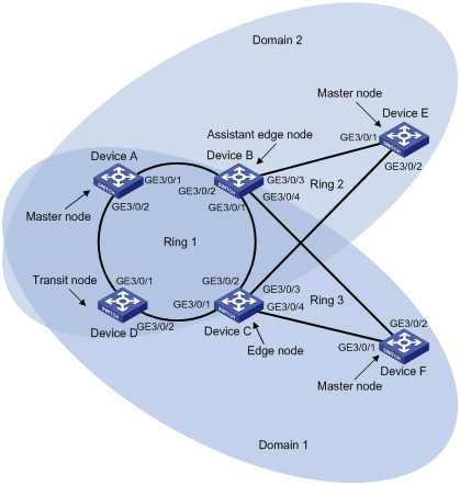
Figure 2-3 Network diagram for intersecting-ring load balancing
Networking and Configuration Requirements
l Device A, Device B, Device C, Device D, and Device F constitute RRPP domain 1, and VLAN 100 is the control VLAN of the RRPP domain. Device A is the master node of the primary ring Ring 1; Device D is the transit node of the primary ring Ring 1; Device F is the master node of the subring Ring 3; Device C is the edge node of the subring Ring 3; Device B is the assistant-edge node of the subring Ring 3.
l Device A, Device B, Device C, Device D, and Device E constitute RRPP domain 2, and VLAN 105 is the control VLAN of the RRPP domain. Device A is the master node of the primary ring Ring 1; Device D is the transit node of the primary ring Ring 1; Device E is the master node of the subring Ring 2; Device C is the edge node of the subring Ring 2; Device B is the assistant-edge node of the subring Ring 2.
l Specify VLAN 10 as the protected VLAN of domain 1, and VLAN 20 as the protected VLAN of domain 2. Thus, you can achieve VLAN-based load balancing on the primary ring.
l As the edge node and assistant-edge node of subring Ring 2 is the same as those of subring Ring 3, and the two subrings have the same link in the primary ring, you can add subrings Ring 2 and Ring 3 to the ring group to reduce Edge-Hello traffic.
Applicable Product Matrix
|
Product series |
Software version |
Hardware version |
|
S7500E series Ethernet switches |
Release 6300 |
All versions |
Configuration Procedure
Configuration considerations:
l Create data VLANs, and map the VLANs to be protected in each RRPP domain to different MSTIs.
l Disable STP on all ports accessing RRPP rings on these devices and configure the VLANs whose traffic is permitted to pass through.
l Create RRPP domains.
l Specify control VLANs for RRPP domains.
l Specify protected VLANs for each domain by specifying MSTIs.
l Specify the roles of devices in these RRPP rings and the ports accessing RRPP rings.
l Enable RRPP rings.
l Enable the RRPP protocol.
l Configure a ring group on the edge nodes and assistant-edge nodes.
1) Configuration on Device A
# Configure Device A as the master node of the primary ring.
# Configure the MSTIs mapped to the protected VLANs.
<DeviceA> system-view
[DeviceA] vlan 10
[DeviceA-vlan10] vlan 20
[DeviceA-vlan20] quit
[DeviceA] stp region-configuration
[DeviceA-mst-region] instance 1 vlan 10
[DeviceA-mst-region] instance 2 vlan 20
[DeviceA-mst-region] active region-configuration
[DeviceA-mst-region] quit
# Configure the ports used to access the RRPP ring on Device A.
[DeviceA] interface gigabitethernet 3/0/1
[DeviceA-GigabitEthernet3/0/1] link-delay 0
[DeviceA-GigabitEthernet3/0/1] stp disable
[DeviceA-GigabitEthernet3/0/1] port link-type trunk
[DeviceA-GigabitEthernet3/0/1] undo port trunk permit vlan 1
[DeviceA-GigabitEthernet3/0/1] port trunk permit vlan 10 20
[DeviceA-GigabitEthernet3/0/1] interface gigabitethernet 3/0/2
[DeviceA-GigabitEthernet3/0/2] link-delay 0
[DeviceA-GigabitEthernet3/0/2] stp disable
[DeviceA-GigabitEthernet3/0/2] port link-type trunk
[DeviceA-GigabitEthernet3/0/2] undo port trunk permit vlan 1
[DeviceA-GigabitEthernet3/0/2] port trunk permit vlan 10 20
[DeviceA-GigabitEthernet3/0/2] quit
# Configure RRPP Domain 1; specify the control VLAN and protected VLANs; configure and enable RRPP ring.
[DeviceA] rrpp domain 1
[DeviceA-rrpp-domain1] control-vlan 100
[DeviceA-rrpp-domain1] protected-vlan reference-instance 1
[DeviceA-rrpp-domain1] ring 1 node-mode master primary-port gigabitethernet 3/0/1 secondary-port gigabitethernet 3/0/2 level 0
[DeviceA-rrpp-domain1] ring 1 enable
[DeviceA-rrpp-domain1] quit
# Configure RRPP Domain 2; specify the control VLAN and protected VLANs; configure and enable RRPP ring.
[DeviceA] rrpp domain 2
[DeviceA-rrpp-domain2] control-vlan 105
[DeviceA-rrpp-domain2] protected-vlan reference-instance 2
[DeviceA-rrpp-domain2] ring 1 node-mode master primary-port gigabitethernet 3/0/2 secondary-port gigabitethernet 3/0/1 level 0
[DeviceA-rrpp-domain2] ring 1 enable
[DeviceA-rrpp-domain2] quit
# Enable RRPP.
[DeviceA] rrpp enable
2) Configuration on Device B
# Configure Device B as the assistant-edge node of subrings Ring 2 and Ring 3.
# Configure the MSTIs mapped to the protected VLANs.
<DeviceB> system-view
[DeviceB] vlan 10
[DeviceB-vlan10] vlan 20
[DeviceB-vlan20] quit
[DeviceB] stp region-configuration
[DeviceB-mst-region] instance 1 vlan 10
[DeviceB-mst-region] instance 2 vlan 20
[DeviceB-mst-region] active region-configuration
[DeviceB-mst-region] quit
# Configure the ports used to access the RRPP ring on Device A.
[DeviceB] interface gigabitethernet 3/0/1
[DeviceB-GigabitEthernet3/0/1] link-delay 0
[DeviceB-GigabitEthernet3/0/1] stp disable
[DeviceB-GigabitEthernet3/0/1] port link-type trunk
[DeviceB-GigabitEthernet3/0/1] undo port trunk permit vlan 1
[DeviceB-GigabitEthernet3/0/1] port trunk permit vlan 10 20
[DeviceB-GigabitEthernet3/0/1] interface gigabitethernet 3/0/2
[DeviceB-GigabitEthernet3/0/2] link-delay 0
[DeviceB-GigabitEthernet3/0/2] stp disable
[DeviceB-GigabitEthernet3/0/2] port link-type trunk
[DeviceB-GigabitEthernet3/0/2] undo port trunk permit vlan 1
[DeviceB-GigabitEthernet3/0/2] port trunk permit vlan 10 20
[DeviceB-GigabitEthernet3/0/2] interface gigabitethernet 3/0/3
[DeviceB-GigabitEthernet3/0/3] link-delay 0
[DeviceB-GigabitEthernet3/0/3] stp disable
[DeviceB-GigabitEthernet3/0/3] port link-type trunk
[DeviceB-GigabitEthernet3/0/3] undo port trunk permit vlan 1
[DeviceB-GigabitEthernet3/0/3] port trunk permit vlan 20
[DeviceB-GigabitEthernet3/0/3] interface gigabitethernet 3/0/4
[DeviceB-GigabitEthernet3/0/4] link-delay 0
[DeviceB-GigabitEthernet3/0/4] stp disable
[DeviceB-GigabitEthernet3/0/4] port link-type trunk
[DeviceB-GigabitEthernet3/0/4] undo port trunk permit vlan 1
[DeviceB-GigabitEthernet3/0/4] port trunk permit vlan 10
[DeviceB-GigabitEthernet3/0/4] quit
# Configure RRPP Domain 1; specify the control VLAN and protected VLANs; configure and enable RRPP ring.
[DeviceB] rrpp domain 1
[DeviceB-rrpp-domain1] control-vlan 100
[DeviceB-rrpp-domain1] protected-vlan reference-instance 1
[DeviceB-rrpp-domain1] ring 1 node-mode transit primary-port gigabitethernet 3/0/1 secondary-port gigabitethernet 3/0/2 level 0
[DeviceB-rrpp-domain1] ring 3 node-mode assistant-edge edge-port gigabitethernet 3/0/4
[DeviceB-rrpp-domain1] ring 1 enable
[DeviceB-rrpp-domain1] ring 3 enable
[DeviceB-rrpp-domain1] quit
# Configure RRPP Domain 2; specify the control VLAN and protected VLANs; configure and enable RRPP ring.
[DeviceB] rrpp domain 2
[DeviceB-rrpp-domain2] control-vlan 105
[DeviceB-rrpp-domain2] protected-vlan reference-instance 2
[DeviceB-rrpp-domain2] ring 1 node-mode transit primary-port gigabitethernet 3/0/1 secondary-port gigabitethernet 3/0/2 level 0
[DeviceB-rrpp-domain2] ring 2 node-mode assistant-edge edge-port gigabitethernet 3/0/3
[DeviceB-rrpp-domain2] ring 1 enable
[DeviceB-rrpp-domain2] ring 2 enable
[DeviceB-rrpp-domain2] quit
# Enable RRPP.
[DeviceB] rrpp enable
3) Configuration on Device C
# Configure Device C as the edge node of subrings Ring 2 and Ring 3.
# Configure the MSTIs mapped to the protected VLANs.
<DeviceC> system-view
[DeviceC] vlan 10
[DeviceC-vlan10] vlan 20
[DeviceC-vlan20] quit
[DeviceC] stp region-configuration
[DeviceC-mst-region] instance 1 vlan 10
[DeviceC-mst-region] instance 2 vlan 20
[DeviceC-mst-region] active region-configuration
[DeviceC-mst-region] quit
# Configure the ports used to access the RRPP ring on Device A.
[DeviceC] interface gigabitethernet 3/0/1
[DeviceC-GigabitEthernet3/0/1] link-delay 0
[DeviceC-GigabitEthernet3/0/1] stp disable
[DeviceC-GigabitEthernet3/0/1] port link-type trunk
[DeviceC-GigabitEthernet3/0/1] undo port trunk permit vlan 1
[DeviceC-GigabitEthernet3/0/1] port trunk permit vlan 10 20
[DeviceC-GigabitEthernet3/0/1] interface gigabitethernet 3/0/2
[DeviceC-GigabitEthernet3/0/2] link-delay 0
[DeviceC-GigabitEthernet3/0/2] stp disable
[DeviceC-GigabitEthernet3/0/2] port link-type trunk
[DeviceC-GigabitEthernet3/0/2] undo port trunk permit vlan 1
[DeviceC-GigabitEthernet3/0/2] port trunk permit vlan 10 20
[DeviceC-GigabitEthernet3/0/2] interface gigabitethernet 3/0/3
[DeviceC-GigabitEthernet3/0/3] link-delay 0
[DeviceC-GigabitEthernet3/0/3] stp disable
[DeviceC-GigabitEthernet3/0/3] port link-type trunk
[DeviceC-GigabitEthernet3/0/3] undo port trunk permit vlan 1
[DeviceC-GigabitEthernet3/0/3] port trunk permit vlan 20
[DeviceC-GigabitEthernet3/0/3] interface gigabitethernet 3/0/4
[DeviceC-GigabitEthernet3/0/4] link-delay 0
[DeviceC-GigabitEthernet3/0/4] stp disable
[DeviceC-GigabitEthernet3/0/4] port link-type trunk
[DeviceC-GigabitEthernet3/0/4] undo port trunk permit vlan 1
[DeviceC-GigabitEthernet3/0/4] port trunk permit vlan 10
[DeviceC-GigabitEthernet3/0/4] quit
# Configure RRPP Domain 1; specify the control VLAN and protected VLANs; configure and enable RRPP ring.
[DeviceC] rrpp domain 1
[DeviceC-rrpp-domain1] control-vlan 100
[DeviceC-rrpp-domain1] protected-vlan reference-instance 1
[DeviceC-rrpp-domain1] ring 1 node-mode transit primary-port gigabitethernet 3/0/1 secondary-port gigabitethernet 3/0/2 level 0
[DeviceC-rrpp-domain1] ring 3 node-mode edge edge-port gigabitethernet 3/0/4
[DeviceC-rrpp-domain1] ring 1 enable
[DeviceC-rrpp-domain1] ring 3 enable
[DeviceC-rrpp-domain1] quit
# Configure RRPP Domain 2; specify the control VLAN and protected VLANs; configure and enable RRPP ring.
[DeviceC] rrpp domain 2
[DeviceC-rrpp-domain2] control-vlan 105
[DeviceC-rrpp-domain2] protected-vlan reference-instance 2
[DeviceC-rrpp-domain2] ring 1 node-mode transit primary-port gigabitethernet 3/0/1 secondary-port gigabitethernet 3/0/2 level 0
[DeviceC-rrpp-domain2] ring 2 node-mode edge edge-port gigabitethernet 3/0/3
[DeviceC-rrpp-domain2] ring 1 enable
[DeviceC-rrpp-domain2] ring 2 enable
[DeviceC-rrpp-domain2] quit
# Enable RRPP.
[DeviceC] rrpp enable
4) Configuration on Device D
# Configure Device D as a transit node of the primary ring.
# Configure the MSTIs mapped to the protected VLANs.
<DeviceD> system-view
[DeviceD] vlan 10
[DeviceD-vlan10] vlan 20
[DeviceD-vlan20] quit
[DeviceD] stp region-configuration
[DeviceD-mst-region] instance 1 vlan 10
[DeviceD-mst-region] instance 2 vlan 20
[DeviceD-mst-region] active region-configuration
[DeviceD-mst-region] quit
# Configure the ports used to access the RRPP ring on Device A.
[DeviceD] interface gigabitethernet 3/0/1
[DeviceD-GigabitEthernet3/0/1] link-delay 0
[DeviceD-GigabitEthernet3/0/1] stp disable
[DeviceD-GigabitEthernet3/0/1] port link-type trunk
[DeviceD-GigabitEthernet3/0/1] undo port trunk permit vlan 1
[DeviceD-GigabitEthernet3/0/1] port trunk permit vlan 10 20
[DeviceD-GigabitEthernet3/0/1] interface gigabitethernet 3/0/2
[DeviceD-GigabitEthernet3/0/2] link-delay 0
[DeviceD-GigabitEthernet3/0/2] stp disable
[DeviceD-GigabitEthernet3/0/2] port link-type trunk
[DeviceD-GigabitEthernet3/0/2] undo port trunk permit vlan 1
[DeviceD-GigabitEthernet3/0/2] port trunk permit vlan 10 20
[DeviceD-GigabitEthernet3/0/2] quit
# Configure RRPP Domain 1; specify the control VLAN and protected VLANs; configure and enable RRPP ring.
[DeviceD] rrpp domain 1
[DeviceD-rrpp-domain1] control-vlan 100
[DeviceD-rrpp-domain1] protected-vlan reference-instance 1
[DeviceD-rrpp-domain1] ring 1 node-mode transit primary-port gigabitethernet 3/0/1 secondary-port gigabitethernet 3/0/2 level 0
[DeviceD-rrpp-domain1] ring 1 enable
[DeviceD-rrpp-domain1] quit
# Configure RRPP Domain 2; specify the control VLAN and protected VLANs; configure and enable RRPP ring.
[DeviceD] rrpp domain 2
[DeviceD-rrpp-domain2] control-vlan 105
[DeviceD-rrpp-domain2] protected-vlan reference-instance 2
[DeviceD-rrpp-domain2] ring 1 node-mode transit primary-port gigabitethernet 3/0/1 secondary-port gigabitethernet 3/0/2 level 0
[DeviceD-rrpp-domain2] ring 1 enable
[DeviceD-rrpp-domain2] quit
# Enable RRPP.
[DeviceD] rrpp enable
5) Configuration on Device E
# Configure Device E as the master node of subring Ring 2 in domain 2.
# Configure the MSTI mapped to the protected VLANs.
<DeviceE> system-view
[DeviceE] vlan 20
[DeviceE-vlan20] quit
[DeviceE] stp region-configuration
[DeviceE-mst-region] instance 2 vlan 20
[DeviceE-mst-region] active region-configuration
[DeviceE-mst-region] quit
# Configure the ports used to access the RRPP ring on Device A.
[DeviceE] interface gigabitethernet 3/0/1
[DeviceE-GigabitEthernet3/0/1] link-delay 0
[DeviceE-GigabitEthernet3/0/1] stp disable
[DeviceE-GigabitEthernet3/0/1] port link-type trunk
[DeviceE-GigabitEthernet3/0/1] undo port trunk permit vlan 1
[DeviceE-GigabitEthernet3/0/1] port trunk permit vlan 20
[DeviceE-GigabitEthernet3/0/1] interface gigabitethernet 3/0/2
[DeviceE-GigabitEthernet3/0/2] link-delay 0
[DeviceE-GigabitEthernet3/0/2] stp disable
[DeviceE-GigabitEthernet3/0/2] port link-type trunk
[DeviceE-GigabitEthernet3/0/2] undo port trunk permit vlan 1
[DeviceE-GigabitEthernet3/0/2] port trunk permit vlan 20
[DeviceE-GigabitEthernet3/0/2] quit
# Configure RRPP Domain 2; specify the control VLAN and protected VLANs; configure and enable RRPP ring.
[DeviceE] rrpp domain 2
[DeviceE-rrpp-domain2] control-vlan 105
[DeviceE-rrpp-domain2] protected-vlan reference-instance 2
[DeviceE-rrpp-domain2] ring 2 node-mode master primary-port gigabitethernet 3/0/2 secondary-port gigabitethernet 3/0/1 level 1
[DeviceE-rrpp-domain2] ring 2 enable
[DeviceE-rrpp-domain2] quit
# Enable RRPP.
[DeviceE] rrpp enable
6) Configuration on Device F
# Configure Device F as the master node of subring Ring 3 in domain 1.
# Configure the MSTI mapped to the protected VLAN.
<DeviceF> system-view
[DeviceF] vlan 10
[DeviceF-vlan10] quit
[DeviceF] stp region-configuration
[DeviceF-mst-region] instance 1 vlan 10
[DeviceF-mst-region] active region-configuration
[DeviceF-mst-region] quit
# Configure the ports used to access the RRPP ring on Device A.
[DeviceF] interface gigabitethernet 3/0/1
[DeviceF-GigabitEthernet3/0/1] link-delay 0
[DeviceF-GigabitEthernet3/0/1] stp disable
[DeviceF-GigabitEthernet3/0/1] port link-type trunk
[DeviceF-GigabitEthernet3/0/1] undo port trunk permit vlan 1
[DeviceF-GigabitEthernet3/0/1] port trunk permit vlan 10
[DeviceF-GigabitEthernet3/0/1] interface gigabitethernet 3/0/2
[DeviceF-GigabitEthernet3/0/2] link-delay 0
[DeviceF-GigabitEthernet3/0/2] stp disable
[DeviceF-GigabitEthernet3/0/2] port link-type trunk
[DeviceF-GigabitEthernet3/0/2] undo port trunk permit vlan 1
[DeviceF-GigabitEthernet3/0/2] port trunk permit vlan 10
[DeviceF-GigabitEthernet3/0/2] quit
# Configure RRPP Domain 1; specify the control VLAN and protected VLANs; configure and enable RRPP ring.
[DeviceF] rrpp domain 1
[DeviceF-rrpp-domain1] control-vlan 100
[DeviceF-rrpp-domain1] protected-vlan reference-instance 1
[DeviceF-rrpp-domain1] ring 3 node-mode master primary-port gigabitethernet 3/0/1 secondary-port gigabitethernet 3/0/2 level 1
[DeviceF-rrpp-domain1] ring 3 enable
[DeviceF-rrpp-domain1] quit
# Enable RRPP.
[DeviceF] rrpp enable
7) Configure a ring group on Device B and Device C after the configurations above
<DeviceB> system-view
[DeviceB] rrpp ring-group 1
[DeviceB-rrpp-ring-group1] domain 2 ring 2
[DeviceB-rrpp-ring-group1] domain 1 ring 3
<DeviceC> system-view
[DeviceC] rrpp ring-group 1
[DeviceC-rrpp-ring-group1] domain 2 ring 2
[DeviceC-rrpp-ring-group1] domain 1 ring 3
Complete Configuration
l Configuration on Device A
#
vlan 10
#
vlan 20
#
stp region-configuration
instance 1 vlan 10
instance 2 vlan 20
active region-configuration
#
interface GigabitEthernet3/0/1
port link-type trunk
undo port trunk permit vlan 1
port trunk permit vlan 10 20
stp disable
#
interface GigabitEthernet3/0/2
port link-type trunk
undo port trunk permit vlan 1
port trunk permit vlan 10 20
stp disable
#
rrpp domain 1
control-vlan 100
protected-vlan reference-instance 1
ring 1 node-mode master primary-port GigabitEthernet3/0/1 secondary-port GigabitEthernet3/0/2 level 0
ring 1 enable
#
rrpp domain 2
control-vlan 105
protected-vlan reference-instance 1
ring 1 node-mode master primary-port GigabitEthernet3/0/2 secondary-port GigabitEthernet3/0/1 level 0
ring 1 enable
#
rrpp enable
#
l Configuration on Device B
#
vlan 10
#
vlan 20
#
stp region-configuration
instance 1 vlan 10
instance 2 vlan 20
active region-configuration
#
interface GigabitEthernet3/0/1
port link-type trunk
undo port trunk permit vlan 1
port trunk permit vlan 10 20
stp disable
#
interface GigabitEthernet3/0/2
port link-type trunk
undo port trunk permit vlan 1
port trunk permit vlan 10 20
stp disable
#
interface GigabitEthernet3/0/3
port link-type trunk
undo port trunk permit vlan 1
port trunk permit vlan 20
stp disable
#
interface GigabitEthernet3/0/4
port link-type trunk
undo port trunk permit vlan 1
port trunk permit vlan 10
stp disable
#
rrpp domain 1
control-vlan 100
protected-vlan reference-instance 1
ring 1 node-mode transit primary-port GigabitEthernet3/0/1 secondary-port GigabitEthernet3/0/2 level 0
ring 3 node-mode assistant-edge edge-port GigabitEthernet3/0/4
ring 1 enable
ring 3 enable
#
rrpp domain 2
control-vlan 105
protected-vlan reference-instance 2
ring 1 node-mode transit primary-port GigabitEthernet3/0/1 secondary-port GigabitEthernet3/0/2 level 0
ring 2 node-mode assistant-edge edge-port GigabitEthernet3/0/3
ring 1 enable
ring 2 enable
#
rrpp ring-group 1
domain 2 ring 2
domain 1 ring 3
#
rrpp enable
#
l Configuration on Device C
#
vlan 10
#
vlan 20
#
stp region-configuration
instance 1 vlan 10
instance 2 vlan 20
active region-configuration
#
interface GigabitEthernet3/0/1
port link-type trunk
undo port trunk permit vlan 1
port trunk permit vlan 10 20
stp disable
#
interface GigabitEthernet3/0/2
port link-type trunk
undo port trunk permit vlan 1
port trunk permit vlan 10 20
stp disable
#
interface GigabitEthernet3/0/3
port link-type trunk
undo port trunk permit vlan 1
port trunk permit vlan 20
stp disable
#
interface GigabitEthernet3/0/4
port link-type trunk
undo port trunk permit vlan 1
port trunk permit vlan 10
stp disable
#
rrpp domain 1
control-vlan 100
protected-vlan reference-instance 1
ring 1 node-mode transit primary-port GigabitEthernet3/0/1 secondary-port GigabitEthernet3/0/2 level 0
ring 3 node-mode edge edge-port GigabitEthernet3/0/4
ring 1 enable
ring 3 enable
#
rrpp domain 2
control-vlan 105
protected-vlan reference-instance 1
ring 1 node-mode transit primary-port GigabitEthernet3/0/1 secondary-port GigabitEthernet3/0/2 level 0
ring 2 node-mode edge edge-port GigabitEthernet3/0/3
ring 1 enable
ring 2 enable
#
rrpp ring-group 1
domain 2 ring 2
domain 1 ring 3
#
rrpp enable
#
l Configuration on Device D
#
vlan 10
#
vlan 20
#
stp region-configuration
instance 1 vlan 10
instance 2 vlan 20
active region-configuration
#
interface GigabitEthernet3/0/1
port link-type trunk
undo port trunk permit vlan 1
port trunk permit vlan 10 20
stp disable
#
interface GigabitEthernet3/0/2
port link-type trunk
undo port trunk permit vlan 1
port trunk permit vlan 10 20
stp disable
#
rrpp domain 1
control-vlan 100
protected-vlan reference-instance 1
ring 1 node-mode transit primary-port GigabitEthernet3/0/1 secondary-port GigabitEthernet3/0/2 level 0
ring 1 enable
#
rrpp domain 2
control-vlan 105
protected-vlan reference-instance 1
ring 1 node-mode transit primary-port GigabitEthernet3/0/1 secondary-port GigabitEthernet3/0/2 level 0
ring 1 enable
#
rrpp enable
#
l Configuration on Device E
#
vlan 20
#
stp region-configuration
instance 2 vlan 20
active region-configuration
#
interface GigabitEthernet3/0/1
port link-type trunk
undo port trunk permit vlan 1
port trunk permit vlan 20
stp disable
#
interface GigabitEthernet3/0/2
port link-type trunk
undo port trunk permit vlan 1
port trunk permit vlan 20
stp disable
#
rrpp domain 2
control-vlan 105
protected-vlan reference-instance 2
ring 2 node-mode master primary-port GigabitEthernet3/0/2 secondary-port GigabitEthernet3/0/1 level 1
ring 2 enable
#
rrpp enable
#
l Configuration on Device F
#
vlan 10
#
stp region-configuration
instance 1 vlan 10
active region-configuration
#
interface GigabitEthernet3/0/1
port link-type trunk
undo port trunk permit vlan 1
port trunk permit vlan 10
stp disable
#
interface GigabitEthernet3/0/2
port link-type trunk
undo port trunk permit vlan 1
port trunk permit vlan 10
stp disable
#
rrpp domain 1
control-vlan 100
protected-vlan reference-instance 1
ring 3 node-mode master primary-port GigabitEthernet3/0/1 secondary-port GigabitEthernet3/0/2 level 1
ring 3 enable
#
rrpp enable
#
Configuration Guidelines
In addition to the precautions in Configuration Guidelines of Configuring a Single-Ring Topology and Configuration Guidelines of Configuring a Intersecting-Ring Topology, make sure that:
l To reduce Edge-Hello traffic, you can adopt the ring group mechanism, that is, assign subrings with the same edge node/assistant-edge node to a ring group. RRPP configured with ring groups cannot interoperate with RRPP that does not support ring group configuration.
l You need to configure ring groups on both the edge node and the assistant-edge node at the same time. The two ring groups must be configured with the same subrings. Otherwise, the ring groups cannot operate properly.
l A subring can be assigned to only one ring group.
l A device must be of the same type, an edge node or an assistant-edge node, in the subrings in a ring group.
l To assign an activated ring to a ring group, first assign the ring to the assistant-edge node ring group and then to the edge node ring group.
l To remove an activated ring from a ring group, first remove the ring from the edge node ring group and then from the assistant-edge node ring group.
l The subrings in a ring group must have the same link in the primary ring. Otherwise, the ring group cannot function properly.
l An edge node ring group and its corresponding assistant-edge node ring group must be the same in configurations and activation status.