- Table of Contents
-
- H3C Low-End and Mid-Range Ethernet Switches Configuration Examples(V1.01)
- 00-1Cover
- 01-Login Configuration Guide
- 02-VLAN Configuration Guide
- 03-GVRP Configuration Guide
- 04-Voice VLAN Configuration Guide
- 05-IP Addressing and Performance Configuration Guide
- 06-QinQ Configuration Guide
- 07-BPDU Tunnel Configuration Guide
- 08-VLAN Mapping Configuration Guide
- 09-MAC Address Table Management Configuration Guide
- 10-Link Aggregation Configuration Guide
- 11-IP Source Guard Configuration Guide
- 12-DLDP Configuration Guide
- 13-MSTP Configuration Guide
- 14-IPv4 Routing Configuration Guide
- 15-IPv6 Configuration Guide
- 16-IPv6 Routing Configuration Guide
- 17-IPv4 Multicast Configuration Guide
- 18-IPv6 Multicast Configuration Examples
- 19-802.1x Configuration Guide
- 20-AAA Configuration Guide
- 21-MAC Authentication Configuration Guide
- 22-Portal Configuration Guide
- 23-ARP Configuration Guide
- 24-DHCP Configuration Guide
- 25-ACL Configuration Guide
- 26-QoS Configuration Guide
- 27-Port Mirroring Configuration Guide
- 28-Cluster Management Configuration Guide
- 29-SNMP-RMON Configuration Guide
- 30-NTP Configuration Guide
- 31-FTP-TFTP Configuration Guide
- 32-UDP Helper Configuration Guide
- 33-Information Center Configuration Guide
- 34-DNS Configuration Guide
- 35-File System Management Configuration Guide
- 36-Remote Upgrade Configuration Guide
- 37-NQA Configuration Guide
- 38-VRRP Configuration Guide
- 39-SSH Configuration Guide
- 40-Port Security Configuration Guide
- 41-Port Isolation Configuration Guide
- 42-LLDP Configuration Guide
- 43-MCE Configuration Guide
- 44-PoE Configuration Guide
- 45-OAM Configuration Guide
- 46-Connectivity Fault Detection Configuration Guide
- 47-RRPP Configuration Guide
- 48-sFlow Configuration Guide
- 49-SSL-HTTPS Configuration Guide
- 50-PKI Configuration Guide
- 51-Track Configuration Guide
- 52-EPON-OLT Configuration Guide
- 53-Smart Link Configuration Guide
- 54-MPLS Configuration Guide
- Related Documents
-
| Title | Size | Download |
|---|---|---|
| 38-VRRP Configuration Guide | 182.67 KB |
Table of Contents
1 IPv4-Based VRRP Configuration Guide
Networking and Configuration Requirements
Configuring VRRP Interface Tracking
Networking and Configuration Requirements
Configuring Multiple VRRP Groups
Networking and Configuration Requirements
2 IPv6-Based VRRP Configuration Guide
Networking and Configuration Requirements
Configuring VRRP Interface Tracking
Networking and Configuration Requirements
Configuring Multiple VRRP Groups
Networking and Configuration Requirements
Configuring Single VRRP Group
Virtual Router Redundancy Protocol (VRRP) is an error-tolerant protocol. Deploying it on multicast and broadcast LANs such as Ethernet, you can ensure that the system can still provide highly reliable default links without changing configurations (such as dynamic routing protocols, route discovery protocols) when a device fails. Backup links facilitate network security and prevent network interruption due to a single link failure.
You can add two or more switches into one VRRP group, which can provide two or more reliable links to the external networks, therefore avoiding communication interruption resulting from single or multi-point failure.
Network Diagram
Figure 1-1 Network diagram for single VRRP group configuration
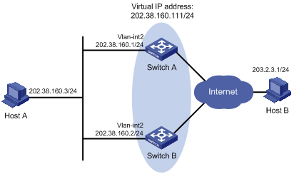
Networking and Configuration Requirements
l Host A needs to access Host B on the Internet, using 202.38.160.111/24 as its default gateway.
l If Switch A operates normally, packets sent from Host A to Host B are forwarded by Switch A; if Switch A fails, packets sent from Host A to Host B are forwarded by Switch B.
VRRP group settings:
l VRRP group number: 1
l Virtual router IP address of the VRRP group: 202.38.160.111
l Switch A acts as the master
l Switch B acts as the backup, and works in the preemptive mode
Table 1-1 Networking description
|
Switch |
Ethernet port connected with Host A |
IP address of the VLAN interface |
Switch priority in the VRRP group |
Working mode |
|
Switch A |
Ethernet 1/0/6 |
202.38.160.1/24 |
110 |
Preemptive mode |
|
Switch B |
Ethernet 1/0/5 |
202.38.160.2/24 |
100 (default) |
Preemptive mode |
Applicable Product Matrix
|
Software version |
Hardware version |
|
|
S3610 Series Ethernet Switches |
Release 5301 Release 5303 |
All versions |
|
S5510 Series Ethernet Switches |
Release 5301 Release 5303 |
All versions |
|
S5500-EI Series Ethernet Switches |
Release 2102 |
All versions |
|
S7500E Series Ethernet Switches |
Release 6100 Release 6300 |
All versions |
Configuration Procedure
# Configure VLAN 2.
<Switch A> system-view
[Switch A] vlan 2
[Switch A-vlan2] port Ethernet1/0/6
[Switch A-vlan2] quit
[Switch A] interface Vlan-interface 2
[Switch A-Vlan-interface2] ip address 202.38.160.1 255.255.255.0
# Create a VRRP group.
[Switch A-Vlan-interface2] vrrp vrid 1 virtual-ip 202.38.160.111
# Set the priority of Switch A in the VRRP group to 110.
[Switch A-Vlan-interface2] vrrp vrid 1 priority 110
# Set Switch A to work in preemptive mode. The preemption delay is five seconds.
[Switch A-Vlan-interface2] vrrp vrid 1 preempt-mode timer delay 5
![]()
A VRRP group works in preemptive mode and the preemption delay is 0 seconds by default.
l Configure Switch B
# Configure VLAN 2.
<Switch B> system-view
[Switch B] vlan 2
[Switch B-Vlan2] port Ethernet1/0/5
[Switch B-Vlan2] quit
[Switch B] interface Vlan-interface 2
[Switch B-Vlan-interface2] ip address 202.38.160.2 255.255.255.0
# Create a VRRP group.
[Switch B-Vlan-interface2] vrrp vrid 1 virtual-ip 202.38.160.111
# Set Switch B to work in preemptive mode. The preemption delay is five seconds.
[Switch B-Vlan-interface2] vrrp vrid 1 preempt-mode timer delay 5
After the configuration, you can use the display vrrp command to verify the configuration.
Normally, Switch A functions as the gateway. When Switch A is turned off or fails, Switch B takes charge of Switch A and functions as the gateway.
Since Switch A works in the preemptive mode, it can become the master again after it resumes to work and function as the gateway.
Complete Configuration
l Configuration on Switch A
#
interface Vlan-interface2
ip address 202.38.160.1 255.255.255.0
vrrp vrid 1 virtual-ip 202.38.160.111
vrrp vrid 1 priority 110
vrrp vrid 1 preempt-mode timer delay 5
#
interface Ethernet1/0/6
port access vlan 2
#
l Configuration on Switch B
interface Vlan-interface2
ip address 202.38.160.2 255.255.255.0
vrrp vrid 1 virtual-ip 202.38.160.111
vrrp vrid 1 preempt-mode timer delay 5
#
interface Ethernet1/0/5
port access vlan 2
#
Configuration Guidelines
Follow these guidelines when configuring single VRRP group:
l Only when the configured virtual IP address and the interface IP address are legal host addresses and belong to the same segment can the VRRP group operate normally. The virtual IP address of the VRRP group cannot be 0.0.0.0, 255.255.255.255, loopback addresses, non class A/B/C addresses or other illegal IP addresses such as 0.0.0.1.
l Ensure that the configurations are consistent in a VRRP group in terms of number of virtual IP addresses, virtual IP address, advertisement interval and authentication mode.
l Excessive traffic or different timer setting on routers can cause the backup timer to time out abnormally and trigger a change of the state. To solve this problem, you can prolong the time interval to send VRRP packets and configure a preemption delay.
Configuring VRRP Interface Tracking
The interface tracking function expands the backup functionality of VRRP. It provides backup not only when the interface to which a VRRP group is assigned fails but also when other interfaces on the switch become unavailable. When a monitored interface goes down, the priority of the switch where the interface resides is automatically decreased by a specified value, allowing a higher priority switch in the VRRP group to become the master.
Network Diagram
Figure 1-2 Network diagram for VRRP interface tracking
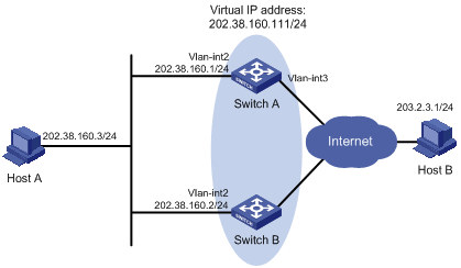
Networking and Configuration Requirements
Configure the interface tracking function to realize the following:
Although Switch A works normally, if its interface connecting with the Internet is not available, Switch B will act as the gateway by using another link to the external networks.
For the ease of explanation, set the number of the VRRP group to 1.
l Host A needs to access Host B on the Internet, using 202.38.160.111/24 as its default gateway.
l Switch A and Switch B belong to VRRP group 1 with the virtual IP address of 202.38.160.111.
l If Switch A operates normally, packets sent from Host A to Host B are forwarded by Switch A; if VLAN-interface 3 through which Switch A connects to the Internet is not available, packets sent from Host A to Host B are forwarded by Switch B.
Applicable Product Matrix
|
Product series |
Software version |
Hardware version |
|
S3610 Series Ethernet Switches |
Release 5301 Release 5303 |
All versions |
|
S5510 Series Ethernet Switches |
Release 5301 Release 5303 |
All versions |
|
S5500-EI Series Ethernet Switches |
Release 2102 |
All versions |
|
S7500E Series Ethernet Switches |
Release 6100 Release 6300 |
All versions |
Configuration Procedure
l Configure Switch A.
# Configure VLAN 2.
<Switch A> system-view
[Switch A] vlan 2
[Switch A-vlan2] port Ethernet1/0/6
[Switch A-vlan2] quit
[Switch A] interface Vlan-interface 2
[Switch A-Vlan-interface2] ip address 202.38.160.1 255.255.255.0
# Create a VRRP group
[Switch A-Vlan-interface2] vrrp vrid 1 virtual-ip 202.38.160.111
# Configure the priority of Switch A in the VRRP group as 110.
[Switch A-Vlan-interface2] vrrp vrid 1 priority 110
# Set the interface to be tracked.
[Switch A-Vlan-interface2] vrrp vrid 1 track interface Vlan-interface 3 reduced 30
l Configure Switch B.
# Configure VLAN 2.
<Switch B> system-view
[Switch B] vlan 2
[Switch B-vlan2] port Ethernet1/0/5
[Switch B-vlan2] quit
[Switch B] interface Vlan-interface 2
[Switch B-Vlan-interface2] ip address 202.38.160.2 255.255.255.0
# Create a VRRP group.
[Switch B-Vlan-interface2] vrrp vrid 1 virtual-ip 202.38.160.111
After the configuration, you can use the display vrrp command to verify the configuration.
When VLAN-interface 3 resumes to work, Switch A becomes the master again and functions as the gateway.
Complete Configuration
l Configuration on Switch A
#
interface Vlan-interface2
ip address 202.38.160.1 255.255.255.0
vrrp vrid 1 virtual-ip 202.38.160.111
vrrp vrid 1 priority 110
vrrp vrid 1 track interface Vlan-interface3 reduced 30
#
interface Ethernet1/0/6
port access vlan 2
#
l Configuration on Switch B
#
interface Vlan-interface2
ip address 202.38.160.2 255.255.255.0
vrrp vrid 1 virtual-ip 202.38.160.111
#
interface Ethernet1/0/5
port access vlan 2
#
Configuration Guidelines
Follow these guidelines when configuring VRRP interface tracking:
l Only when the configured virtual IP address and the interface IP address are legal host addresses and belong to the same segment can the VRRP group operate normally. The virtual IP address of the VRRP group cannot be 0.0.0.0, 255.255.255.255, loopback addresses, non class A/B/C addresses or other illegal IP addresses such as 0.0.0.1.
l Interface tracking is not configurable on an IP address owner.
l When configuring VRRP interface tracking, you are recommended to configure the uplink trunk port to deny the VLAN that corresponds to the tracked interface.
l If the state of the interface under tracking changes from down to up, the priority of the device where the interface resides is restored automatically.
l When configuring the priority decreasing value, ensure that after the priority of the switch is automatically decreased, the priority is lower than that of any switch in the VRRP group, allowing a higher priority switch to become the master.
l Ensure that the configurations are consistent in a VRRP group in terms of number of virtual IP addresses, virtual IP address, advertisement interval and authentication mode.
l Excessive traffic or different timer setting on routers can cause the backup timer to time out abnormally and trigger a change of the state. To solve this problem, you can prolong the time interval to send VRRP packets and configure a preemption delay.
Configuring Multiple VRRP Groups
Multiple VRRP groups can implement link backup and load balancing functions, which can avoid communication interruption resulting from switch failure or traffic overburden on a link.
Network Diagram
Figure 1-3 Network diagram for multiple VRRP group configuration
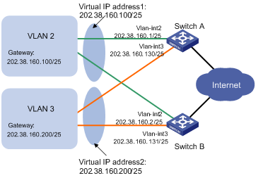
Networking and Configuration Requirements
l Switch A and Switch B belong to both VRRP group 1 and VRRP group 2. The virtual IP address of VRRP group 1 is 202.38.160.100/25, and that of VRRP group 2 is 202.38.160.200/25.
l In VRRP group 1, Switch A has a higher priority than Switch B. In VRRP group 2, Switch B has a higher priority than Switch A. In this case, hosts in VLAN 2 and VLAN 3 can communicate with the outside through Switch A and Switch B respectively, and if Switch A or Switch B fails, the hosts can use the other switch to communicate with the outside, so as to avoid communication interruption.
Applicable Product Matrix
|
Product series |
Software version |
Hardware version |
|
S3610 Series Ethernet Switches |
Release 5301 Release 5303 |
All versions |
|
S5510 Series Ethernet Switches |
Release 5301 Release 5303 |
All versions |
|
S5500-EI Series Ethernet Switches |
Release 2102 |
All versions |
|
S7500E Series Ethernet Switches |
Release 6100 Release 6300 |
All versions |
Configuration Procedure
# Configure VLAN 2.
<Switch A> system-view
[Switch A] vlan 2
[Switch A-vlan2] port Ethernet1/0/5
[Switch A-vlan2] quit
[Switch A] interface Vlan-interface 2
[Switch A-Vlan-interface2] ip address 202.38.160.1 255.255.255.128
# Create VRRP group 1 and set its virtual IP address to 202.38.160.100.
[Switch A-Vlan-interface2] vrrp vrid 1 virtual-ip 202.38.160.100
# Configure the priority of Switch A in VRRP group 1 as 110.
[Switch A-Vlan-interface2] vrrp vrid 1 priority 110
[Switch A-Vlan-interface2] quit
# Configure VLAN 3.
[Switch A] vlan 3
[Switch A-vlan3] port Ethernet 1/0/6
[Switch A-vlan3] quit
[Switch A] interface vlan-interface 3
[Switch A-Vlan-interface3] ip address 202.38.160.130 255.255.255.128
# Create VRRP group 2 and set its virtual IP address to 202.38.160.200.
[Switch A-Vlan-interface3] vrrp vrid 2 virtual-ip 202.38.160.200
l Configure Switch B
# Configure VLAN 2.
<Switch B> system-view
[Switch B] vlan 2
[Switch B-vlan2] port Ethernet1/0/5
[Switch B-vlan2] quit
[Switch B] interface Vlan-interface 2
[Switch B-Vlan-interface2] ip address 202.38.160.2 255.255.255.128
# Create VRRP group 1 and set its virtual IP address to 202.38.160.100.
[Switch B-Vlan-interface2] vrrp vrid 1 virtual-ip 202.38.160.100
[Switch B-Vlan-interface2] quit
# Configure VLAN 3.
[Switch B] vlan 3
[Switch B-vlan3] port Ethernet 1/0/6
[Switch B-vlan3] quit
[Switch B] interface vlan-interface 3
[Switch B-Vlan-interface3] ip address 202.38.160.131 255.255.255.128
# Create VRRP group 2 and set its virtual IP address to 202.38.160.200.
[Switch B-Vlan-interface3] vrrp vrid 2 virtual-ip 202.38.160.200
# Configure the priority of Switch B in VRRP group 2 as 110.
[Switch B-Vlan-interface3] vrrp vrid 2 priority 110
After the configuration, you can use the display vrrp command to verify the configuration.
In VRRP group 1 Switch A is the master, Switch B is the backup and hosts with the default gateway of 202.38.160.100/25 access the Internet through Switch A; in VRRP group 2 Switch A is the backup, Switch B is the master and hosts with the default gateway of 202.38.160.200/25 access the Internet through Switch B.
Complete Configuration
#
interface Vlan-interface2
ip address 202.38.160.1 255.255.255.128
vrrp vrid 1 virtual-ip 202.38.160.100
vrrp vrid 1 priority 110
#
interface Vlan-interface3
ip address 202.38.160.130 255.255.255.128
vrrp vrid 2 virtual-ip 202.38.160.200
#
interface Ethernet1/0/5
port access vlan 2
#
interface Ethernet1/0/6
port access vlan 3
#
l Configuration on Switch B
#
interface Vlan-interface2
ip address 202.38.160.2 255.255.255.128
vrrp vrid 1 virtual-ip 202.38.160.100
#
interface Vlan-interface3
ip address 202.38.160.131 255.255.255.128
vrrp vrid 2 virtual-ip 202.38.160.200
vrrp vrid 2 priority 110
#
interface Ethernet1/0/5
port access vlan 2
#
interface Ethernet1/0/6
port access vlan 3
#
Configuration Guidelines
Follow these guidelines when configuring VRRP interface tracking:
l Only when the configured virtual IP address and the interface IP address are legal host addresses and belong to the same segment can the VRRP group operate normally. The virtual IP address of the VRRP group cannot be 0.0.0.0, 255.255.255.255, loopback addresses, non class A/B/C addresses or other illegal IP addresses such as 0.0.0.1.
l Ensure that the configurations are consistent in a VRRP group in terms of number of virtual IP addresses, virtual IP address, advertisement interval and authentication.
l Excessive traffic or different timer setting on routers can cause the backup timer to time out abnormally and trigger a change of the state. To solve this problem, you can prolong the time interval to send VRRP packets and configure a preemption delay.
Configuring Single VRRP Group
There are two VRRP versions: VRRPv2 and VRRPv3. VRRPv2 is based on IPv4, while VRRPv3 is based on IPv6. The two versions implement the same functions but provide different commands.
You can add two or more switches into one VRRP group, which can provide two or more reliable links to the external networks, therefore avoiding communication interruption resulting from single or multi-point failure.
Network Diagram
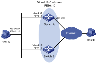
Figure 2-1 Network diagram for single VRRP group configuration
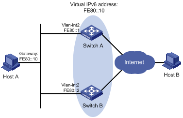
Networking and Configuration Requirements
l Host A needs to access Host B on the Internet, using FE80::10 as its default gateway.
l Switch A and Switch B belong to VRRP group 1 with the virtual IP address of FE80::10.
l If Switch A operates normally, packets sent from Host A to Host B are forwarded by Switch A; if Switch A fails, packets sent from Host A to Host B are forwarded by Switch B.
Applicable Product Matrix
|
Product series |
Software version |
Hardware version |
|
S3610 Series Ethernet Switches |
Release 5301 Release 5303 |
All versions |
|
S5510 Series Ethernet Switches |
Release 5301 Release 5303 |
All versions |
|
S5500-EI Series Ethernet Switches |
Release 2102 |
All versions |
|
S7500E Series Ethernet Switches |
Release 6100 Release 6300 |
All versions |
Configuration Procedure
![]()
Before enabling IPv6 on an S3610/S5510 series Ethernet switch, you need to configure the device to operate in the IPv4/IPv6 dual-stack mode by using the switch-mode dual-ipv4-ipv6 command. Otherwise, IPv6 packets cannot be forwarded on the device even if IPv6 is enabled. The switch-mode command takes effect after the device is rebooted.
l Configure Switch A.
# Configure VLAN 2.
<Switch A> system-view
[Switch A] ipv6
[Switch A] vlan 2
[Switch A-vlan2] port Ethernet1/0/6
[Switch A-vlan2] quit
[Switch A] interface Vlan-interface 2
[Switch A-Vlan-interface2] ipv6 address fe80::1 link-local
[Switch A-Vlan-interface2] ipv6 address 1::1 64
# Create a VRRP group.
[Switch A-Vlan-interface2] vrrp ipv6 vrid 1 virtual-ip fe80::10 link-local
# Set the priority of Switch A in the VRRP group.
[Switch A-Vlan-interface2] vrrp ipv6 vrid 1 priority 110
# Set Switch A to work in preemptive mode.
[Switch A-Vlan-interface2] vrrp ipv6 vrid 1 preempt-mode
![]()
A VRRP group works in preemptive mode and the preemption delay is 0 seconds by default.
# Enable Switch A to send RA messages.
[Switch A-Vlan-interface2] undo ipv6 nd ra halt
l Configure Switch B.
# Configure VLAN 2.
<Switch B> system-view
[Switch B] ipv6
[Switch B] vlan 2
[Switch B-Vlan2] port Ethernet1/0/5
[Switch B-Vlan2] quit
[Switch B] interface Vlan-interface 2
[Switch B-Vlan-interface2] ipv6 address fe80::2 link-local
[Switch B-Vlan-interface2] ipv6 address 1::2 64
# Create VRRP group 1.
[Switch B-Vlan-interface2] vrrp ipv6 vrid 1 virtual-ip fe80::10 link-local
# Enable Switch B to send RA messages.
[Switch B-Vlan-interface2] undo ipv6 nd ra halt
After the configuration, Host B can be pinged on Host A. You can use the display vrrp ipv6 command to verify the configuration.
Normally, Switch A functions as the gateway. When Switch A is turned off or fails, Switch B takes charge of Switch A and functions as the gateway.
Since Switch A works in the preemptive mode, it can become the master again after it resumes to work and function as the gateway.
Complete Configuration
l Configuration on Switch A
#
ipv6
#
interface Vlan-interface2
ipv6 address fe80::1 link-local
ipv6 address 1::1 64
vrrp ipv6 vrid 1 virtual-ip fe80::10 link-local
vrrp ipv6 vrid 1 priority 110
undo ipv6 nd ra halt
#
interface Ethernet1/0/6
port access vlan 2
#
l Configuration on Switch B
#
ipv6
#
interface Vlan-interface2
ipv6 address fe80::2 link-local
ipv6 address 1::2 64
vrrp ipv6 vrid 1 virtual-ip fe80::10 link-local
undo ipv6 nd ra halt
#
interface Ethernet1/0/5
port access vlan 2
#
Configuration Guidelines
Follow these guidelines when configuring VRRP interface tracking:
l Ensure that the configurations are consistent in a VRRP group in terms of number of virtual IP addresses, virtual IP address, advertisement interval and authentication.
l Excessive traffic or different timer setting on routers can cause the backup timer to time out abnormally and trigger a change of the state. To solve this problem, you can prolong the time interval to send VRRP packets and configure a preemption delay.
Configuring VRRP Interface Tracking
The interface tracking function expands the backup functionality of VRRP. It provides backup not only when the interface to which a VRRP group is assigned fails but also when other interfaces on the switch become unavailable. When a monitored interface goes down, the priority of the switch where the interface resides is automatically decreased by a specified value, allowing a higher priority switch in the VRRP group to become the master.
Network Diagram
Figure 2-2 Network diagram for VRRP interface tracking
Networking and Configuration Requirements
Configure the interface tracking function to realize the following:
Although Switch A works normally, if its interface connecting with the Internet is not available, Switch B will act as the gateway by using another link to the outside.
For the ease of explanation, set the number of the backup group to 1.
l Host A needs to access Host B on the Internet, using FE80::10 as its default gateway.
l Switch A and Switch B belong to VRRP group 1 with the virtual IP address of FE80::10.
l If Switch A operates normally, packets sent from Host A to Host B are forwarded by Switch A; if VLAN-interface 3 through which Switch A connects to the Internet is not available, packets sent from Host A to Host B are forwarded by Switch B.
Applicable Product Matrix
|
Product series |
Software version |
Hardware version |
|
S3610 Series Ethernet Switches |
Release 5301 Release 5303 |
All versions |
|
S5510 Series Ethernet Switches |
Release 5301 Release 5303 |
All versions |
|
S5500-EI Series Ethernet Switches |
Release 2102 |
All versions |
|
S7500E Series Ethernet Switches |
Release 6100 Release 6300 |
All versions |
Configuration Procedure
![]()
Before enabling IPv6 on an S3610/S5510 series Ethernet switch, you need to configure the device to operate in the IPv4/IPv6 dual-stack mode by using the switch-mode dual-ipv4-ipv6 command. Otherwise, IPv6 packets cannot be forwarded on the device even if IPv6 is enabled. The switch-mode command takes effect after the device is rebooted.
l Configure Switch A.
# Configure VLAN 2.
<Switch A> system-view
[Switch A] ipv6
[Switch A] vlan 2
[Switch A-vlan2] port Ethernet1/0/6
[Switch A-vlan2] quit
[Switch A] interface Vlan-interface 2
[Switch A-Vlan-interface2] ipv6 address fe80::1 link-local
[Switch A-Vlan-interface2] ipv6 address 1::1 64
# Create a VRRP group.
[Switch A-Vlan-interface2] vrrp ipv6 vrid 1 virtual-ip fe80::10 link-local
# Set the priority of Switch A in VRRP group 1
[Switch A-Vlan-interface2] vrrp ipv6 vrid 1 priority 110
# Set Switch A to work in preemptive mode. The preemption delay is five seconds.
[Switch A-Vlan-interface2] vrrp ipv6 vrid 1 preempt-mode timer delay 5
# Set the interface to be tracked.
[Switch A-Vlan-interface2] vrrp ipv6 vrid 1 track interface Vlan-interface 3 reduced 30
l Configure Switch B.
# Configure VLAN 2.
<Switch B> system-view
[Switch B] ipv6
[Switch B] vlan 2
[Switch B-vlan2] port Ethernet1/0/5
[Switch B-vlan2] quit
[Switch B] interface Vlan-interface 2
[Switch B-Vlan-interface2] ipv6 address fe80::2 link-local
[Switch B-Vlan-interface2] ipv6 address 1::2 64
# Create a VRRP group.
[Switch B-Vlan-interface2] vrrp ipv6 vrid 1 virtual-ip fe80::10 link-local
# Set Switch B to work in preemptive mode. The preemption delay is five seconds.
[SwitchB-Vlan-interface2] vrrp ipv6 vrid 1 preempt-mode timer delay 5
After the configuration, you can use the display vrrp ipv6 command to verify the configuration.
Normally, Switch A acts as the gateway. If VLAN-interface 3 on Switch A is unavailable, the priority of Switch A will be decreased by 30, making the priority of Switch A lower than that of Switch B. Therefore, Switch B will become the master and function as the gateway.
When VLAN-interface 3 resumes to work, Switch A becomes the master again and functions as the gateway.
Complete Configuration
l Configuration on Switch A
#
ipv6
#
interface Vlan-interface2
ipv6 address fe80::1 link-local
ipv6 address 1::1 64
vrrp ipv6 vrid 1 virtual-ip fe80::10 link-local
vrrp ipv6 vrid 1 priority 110
vrrp ipv6 vrid 1 preempt-mode timer delay 5
vrrp ipv6 vrid 1 track interface Vlan-interface3 reduced 30
#
interface Ethernet1/0/6
port access vlan 2
#
l Configuration on Switch B
#
ipv6
#
interface Vlan-interface2
ipv6 address fe80::2 link-local
ipv6 address 1::2 64
vrrp ipv6 vrid 1 virtual-ip fe80::10 link-local
vrrp ipv6 vrid 1 preempt-mode timer delay 5
#
interface Ethernet1/0/5
port access vlan 2
#
Configuration Guidelines
Follow these guidelines when configuring VRRP interface tracking:
l Interface tracking is not configurable on an IP address owner.
l When configuring VRRP interface tracking, you are recommended to configure the uplink trunk port to deny the VLAN that corresponds to the tracked interface.
l If the state of the interface under tracking changes from down to up, the priority of the device corresponding to the interface is restored automatically.
l When configuring the priority decreasing value, ensure that after the priority of the switch is automatically decreased, the priority is lower than that of any switch in the VRRP group, allowing a higher priority switch to become the master.
l Ensure that the configurations are consistent in a VRRP group in terms of number of virtual IP addresses, virtual IP address, advertisement interval and authentication.
l Excessive traffic or different timer setting on routers can cause the backup timer to time out abnormally and trigger a change of the state. To solve this problem, you can prolong the time interval to send VRRP packets and configure a preemption delay.
Configuring Multiple VRRP Groups
Multiple VRRP groups can implement link backup and load balancing functions, which can avoid communication interruption resulting from switch failure or traffic overburden on a link.
Network Diagram
Figure 2-3 Network diagram for multiple VRRP group configuration
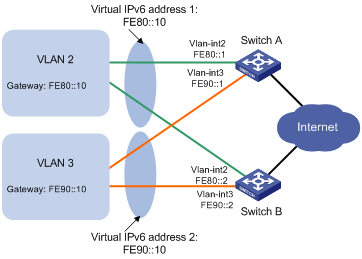
Networking and Configuration Requirements
l Hosts in VLAN 2 use FE80::10 as their default gateway and hosts in VLAN 3 use FE90::10 as their default gateway.
l Switch A and Switch B belong to both VRRP group 1 and VRRP group 2. The virtual IPv6 address of VRRP group 1 is FE80::10, and that of VRRP group 2 is FE90::10.
l In VRRP group 1, Switch A has a higher priority than Switch B. In VRRP group 2, Switch B has a higher priority than Switch A. In this case, hosts in VLAN 1 and VLAN 3 can communicate with the outside through Switch A and Switch B respectively, and if Switch A or Switch B fails, the hosts can use the other switch to communicate with the outside, so as to avoid communication interruption.
Applicable Product Matrix
|
Product series |
Software version |
Hardware version |
|
S3610 Series Ethernet Switches |
Release 5301 Release 5303 |
All versions |
|
S5510 Series Ethernet Switches |
Release 5301 Release 5303 |
All versions |
|
S5500-EI Series Ethernet Switches |
Release 2102 |
All versions |
|
S7500E Series Ethernet Switches |
Release 6100 Release 6300 |
All versions |
Configuration Procedure
![]()
Before enabling IPv6 on an S3610/S5510 series Ethernet switch, you need to configure the device to operate in the IPv4/IPv6 dual-stack mode by using the switch-mode dual-ipv4-ipv6 command. Otherwise, IPv6 packets cannot be forwarded on the device even if IPv6 is enabled. The switch-mode command takes effect after the device is rebooted.
l Configure Switch A
# Configure VLAN 2.
<Switch A> system-view
[Switch A] ipv6
[Switch A] vlan 2
[Switch A-vlan2] port Ethernet1/0/5
[Switch A-vlan2] quit
[Switch A] interface Vlan-interface 2
[Switch A-Vlan-interface2] ipv6 address fe80::1 link-local
[Switch A-Vlan-interface2] ipv6 address 1::1 64
# Create VRRP group 1 and set its virtual IPv6 address to FE80::10.
[Switch A-Vlan-interface2] vrrp ipv6 vrid 1 virtual-ip fe80::10 link-local
# Set the priority of Switch A in VRRP group 1 to 110.
[Switch A-Vlan-interface2] vrrp ipv6 vrid 1 priority 110
[Switch A-Vlan-interface2] quit
# Configure VLAN 3.
[Switch A] vlan 3
[Switch A-vlan3] port Ethernet 1/0/6
[Switch A-vlan3] quit
[Switch A] interface vlan-interface 3
[Switch A-Vlan-interface3] ipv6 address fe90::1 link-local
[Switch A-Vlan-interface3] ipv6 address 2::1 64
# Create VRRP group 2 and set its virtual IPv6 address to FE90::10.
[Switch A-Vlan-interface3] vrrp ipv6 vrid 2 virtual-ip fe90::10 link-local
l Configure Switch B
# Configure VLAN 2.
<Switch B> system-view
[Switch A] ipv6
[Switch B] vlan 2
[Switch B-vlan2] port Ethernet1/0/5
[Switch B-vlan2] quit
[Switch B] interface Vlan-interface 2
[Switch B-Vlan-interface2] ipv6 address fe80::2 link-local
[Switch B-Vlan-interface2] ipv6 address 1::2 64
# Create VRRP group 1 and set its virtual IPv6 address to FE80::10.
[Switch B-Vlan-interface2] vrrp ipv6 vrid 1 virtual-ip fe80::10 link-local
[Switch B-Vlan-interface2] quit
# Configure VLAN 3.
[Switch B] vlan 3
[Switch B-vlan3] port Ethernet 1/0/6
[Switch B-vlan3] quit
[Switch B] interface vlan-interface 3
[Switch B-Vlan-interface3] ipv6 address fe90::2 link-local
[Switch B-Vlan-interface3] ipv6 address 2::2 64
# Create VRRP group 2 and set its virtual IPv6 address to FE90::10.
[Switch B-Vlan-interface3] vrrp ipv6 vrid 2 virtual-ip fe90::10 link-local
# Set the priority of Switch B in VRRP group 2 to 110.
[Switch B-Vlan-interface3] vrrp ipv6 vrid 2 priority 110
After the configuration, you can use the display vrrp command to verify the configuration.
In VRRP group 1 Switch A is the master, Switch B is the backup and hosts with the default gateway of FE80::10 accesses the Internet through Switch A; in VRRP group 2 Switch A is the backup, Switch B is the master and hosts with the default gateway of FE90::10 accesses the Internet through Switch B.
Complete Configuration
l Configuration on Switch A
#
ipv6
#
interface Vlan-interface2
ipv6 address fe80::1 link-local
ipv6 address 1::1 64
vrrp ipv6 vrid 1 virtual-ip fe80::10 link-local
vrrp ipv6 vrid 1 priority 110
#
interface Vlan-interface3
ipv6 address fe90::1 link-local
ipv6 address 2::1 64
vrrp ipv6 vrid 2 virtual-ip fe90::10 link-local
#
interface Ethernet1/0/5
port access vlan 2
#
interface Ethernet1/0/6
port access vlan 3
#
l Configuration on Switch B
#
ipv6
#
interface Vlan-interface2
ipv6 address fe80::2 link-local
ipv6 address 1::2 64
vrrp ipv6 vrid 1 virtual-ip fe80::10 link-local
#
interface Vlan-interface3
ipv6 address fe90::2 link-local
ipv6 address 2::2 64
vrrp ipv6 vrid 2 virtual-ip fe80::20 link-local
vrrp ipv6 vrid 2 priority 110
#
interface Ethernet1/0/5
port access vlan 2
#
interface Ethernet1/0/6
port access vlan 3
#
Configuration Guidelines
Follow these guidelines when configuring VRRP interface tracking:
l In an IPv6 network, to implement load balancing among multiple VRRP groups, you need to manually configure the default gateway for hosts.
l Ensure that the configurations are consistent in a VRRP group in terms of number of virtual IP addresses, virtual IP address, advertisement interval and authentication.
l Excessive traffic or different timer setting on routers can cause the backup timer to time out abnormally and trigger a change of the state. To solve this problem, you can prolong the time interval to send VRRP packets and configure a preemption delay.