- Table of Contents
-
- H3C Low-End and Mid-Range Ethernet Switches Configuration Examples(V1.01)
- 00-1Cover
- 01-Login Configuration Guide
- 02-VLAN Configuration Guide
- 03-GVRP Configuration Guide
- 04-Voice VLAN Configuration Guide
- 05-IP Addressing and Performance Configuration Guide
- 06-QinQ Configuration Guide
- 07-BPDU Tunnel Configuration Guide
- 08-VLAN Mapping Configuration Guide
- 09-MAC Address Table Management Configuration Guide
- 10-Link Aggregation Configuration Guide
- 11-IP Source Guard Configuration Guide
- 12-DLDP Configuration Guide
- 13-MSTP Configuration Guide
- 14-IPv4 Routing Configuration Guide
- 15-IPv6 Configuration Guide
- 16-IPv6 Routing Configuration Guide
- 17-IPv4 Multicast Configuration Guide
- 18-IPv6 Multicast Configuration Examples
- 19-802.1x Configuration Guide
- 20-AAA Configuration Guide
- 21-MAC Authentication Configuration Guide
- 22-Portal Configuration Guide
- 23-ARP Configuration Guide
- 24-DHCP Configuration Guide
- 25-ACL Configuration Guide
- 26-QoS Configuration Guide
- 27-Port Mirroring Configuration Guide
- 28-Cluster Management Configuration Guide
- 29-SNMP-RMON Configuration Guide
- 30-NTP Configuration Guide
- 31-FTP-TFTP Configuration Guide
- 32-UDP Helper Configuration Guide
- 33-Information Center Configuration Guide
- 34-DNS Configuration Guide
- 35-File System Management Configuration Guide
- 36-Remote Upgrade Configuration Guide
- 37-NQA Configuration Guide
- 38-VRRP Configuration Guide
- 39-SSH Configuration Guide
- 40-Port Security Configuration Guide
- 41-Port Isolation Configuration Guide
- 42-LLDP Configuration Guide
- 43-MCE Configuration Guide
- 44-PoE Configuration Guide
- 45-OAM Configuration Guide
- 46-Connectivity Fault Detection Configuration Guide
- 47-RRPP Configuration Guide
- 48-sFlow Configuration Guide
- 49-SSL-HTTPS Configuration Guide
- 50-PKI Configuration Guide
- 51-Track Configuration Guide
- 52-EPON-OLT Configuration Guide
- 53-Smart Link Configuration Guide
- 54-MPLS Configuration Guide
- Related Documents
-
| Title | Size | Download |
|---|---|---|
| 24-DHCP Configuration Guide | 271.45 KB |
Configuring Static IP Address Allocation
Networking and Configuration Requirements
Configuring Dynamic IP Address Allocation
Networking and Configuration Requirements
Networking and Configuration Requirements
Networking and Configuration Requirements
Configuring DHCP Snooping Option 82 Support
Networking and Configuration Requirements
Networking and Configuration Requirements
Configuring Auto-Configuration
Networking and Configuration Requirements
1 DHCP Configuration Guide
Configuring Static IP Address Allocation
Network Diagram
Figure 1-1 Network diagram for static IP address allocation
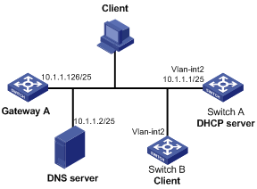
Networking and Configuration Requirements
Switch B (DHCP client) obtains a static IP address, DNS server address, and gateway address from Switch A (DHCP server).
Applicable Product Matrix
|
Product series |
Software version |
Hardware version |
|
S3610 Series Ethernet Switches |
Release 5301 Release 5303 |
All versions |
|
S5510 Series Ethernet Switches |
Release 5301 Release 5303 |
All versions |
|
S5500-EI Series Ethernet Switches |
Release 2102 |
All versions |
|
S7500E Series Ethernet Switches |
Release 6100 Release 6300 |
All versions |
|
S3500-EA Series Ethernet Switches |
Release 5303 |
All versions |
Configuration Procedure
# Configure the IP address of VLAN-interface 2 on Switch A.
<SwitchA> system-view
[SwitchA] interface vlan-interface 2
[SwitchA-Vlan-interface2] ip address 10.1.1.1 25
[SwitchA-Vlan-interface2] quit
# Enable DHCP.
[SwitchA] dhcp enable
# Create DHCP address pool 0, and configure a static IP-MAC binding, DNS server and gateway in it.
[SwitchA] dhcp server ip-pool 0
[SwitchA-dhcp-pool-0] static-bind ip-address 10.1.1.5
[SwitchA-dhcp-pool-0] static-bind mac-address 000f-e200-0002
[SwitchA-dhcp-pool-0] dns-list 10.1.1.2
[SwitchA-dhcp-pool-0] gateway-list 10.1.1.126
[SwitchA-dhcp-pool-0] quit
Complete Configuration
#
dhcp server ip-pool 0
static-bind ip-address 10.1.1.5 mask 255.0.0.0
static-bind mac-address 000f-e200-0002
gateway-list 10.1.1.126
dns-list 10.1.1.2
expired unlimited
#
interface Vlan-interface2
ip address 10.1.1.1 255.255.255.128
#
dhcp enable
#
Configuration Guidelines
l The IP address of a static binding cannot be an interface’s address of the DHCP server. Otherwise, an IP address conflict may occur and the bound client cannot obtain an IP address correctly.
l A DHCP address pool now supports only one static binding, which can be a MAC-to-IP or ID-to-IP binding (a client ID is a string of 4 to 160 characters that uniquely identifies a client).
l The ID of the static binding must be identical to the ID displayed by using the display dhcp client verbose command on the client. Otherwise, the client cannot obtain an IP address.
Configuring Dynamic IP Address Allocation
Network Diagram
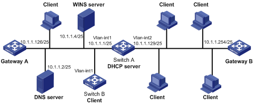
Figure 1-2 Network diagram for dynamic IP address allocation
Networking and Configuration Requirements
l The DHCP server (Switch A) assigns IP addresses to clients in subnet 10.1.1.0/24, which is subnetted into 10.1.1.0/25 and 10.1.1.128/25.
l The IP addresses of VLAN interfaces 1 and 2 on Switch A are 10.1.1.1/25 and 10.1.1.129/25 respectively.
l In the subnet 10.1.1.0/25, the address lease duration is ten days and twelve hours, domain name is aabbcc.com, DNS server address is 10.1.1.2/25, WINS server address is 10.1.1.4/25, and gateway address is 10.1.1.126/25.
l In the subnet 10.1.1.128/25, the address lease duration is five days, domain name is aabbcc.com, DNS server address is 10.1.1.2/25 gateway address is 10.1.1.254/25 and there is no WINS server address.
l The domain name and DNS server address on subnets 10.1.1.0/25 and 10.1.1.128/25 are the same. Therefore, they can be configured only for the subnet 10.1.1.0/24 and the other two subnets can inherit the configuration.
l Enable unauthorized DHCP server detection on Switch A for the administrator to find unauthorized DHCP servers from the log information.
Applicable Product Matrix
|
Product series |
Software version |
Hardware version |
|
S3610 Series Ethernet Switches |
Release 5301 Release 5303 |
All versions |
|
S5510 Series Ethernet Switches |
Release 5301 Release 5303 |
All versions |
|
S5500-EI Series Ethernet Switches |
Release 2102 |
All versions |
|
S7500E Series Ethernet Switches |
Release 6100 Release 6300 |
All versions |
|
S3500-EA Series Ethernet Switches |
Release 5303 |
All versions |
Configuration Procedure
# Enable DHCP.
[SwitchA] dhcp enable
# Exclude IP addresses from dynamic allocation (addresses of the DNS server, WINS server, and gateways).
[SwitchA] dhcp server forbidden-ip 10.1.1.2
[SwitchA] dhcp server forbidden-ip 10.1.1.4
[SwitchA] dhcp server forbidden-ip 10.1.1.126
[SwitchA] dhcp server forbidden-ip 10.1.1.254
# Enable unauthorized DHCP server detection.
[SwitchA] dhcp server detect
# Configure DHCP address pool 0, including address range, domain name and DNS server address.
[SwitchA] dhcp server ip-pool 0
[SwitchA-dhcp-pool-0] network 10.1.1.0 mask 255.255.255.0
[SwitchA-dhcp-pool-0] domain-name aabbcc.com
[SwitchA-dhcp-pool-0] dns-list 10.1.1.2
[SwitchA-dhcp-pool-0] quit
# Configure DHCP address pool 1, including address range, gateway, WINS server address, and lease time.
[SwitchA] dhcp server ip-pool 1
[SwitchA-dhcp-pool-1] network 10.1.1.0 mask 255.255.255.128
[SwitchA-dhcp-pool-1] gateway-list 10.1.1.126
[SwitchA-dhcp-pool-1] expired day 10 hour 12
[SwitchA-dhcp-pool-1] nbns-list 10.1.1.4
[SwitchA-dhcp-pool-1] quit
# Configure DHCP address pool 2 (address range, gateway, and lease duration).
[SwitchA] dhcp server ip-pool 2
[SwitchA-dhcp-pool-2] network 10.1.1.128 mask 255.255.255.128
[SwitchA-dhcp-pool-2] expired day 5
[SwitchA-dhcp-pool-2] gateway-list 10.1.1.254
[SwitchA-dhcp-pool-2] quit
With the unauthorized DHCP server detection enabled, Switch A records all the DHCP servers, including the authorized DHCP server. Then, the administrator can find unauthorized DHCP servers from the log information. When an unauthorized DHCP server is detected, the following log information is displayed.
<SwitchA>
%Apr 30 08:07:51:896 2000 H3C DHCPS/4/DHCPS_LOCAL_SERVER:
Local DHCP server information: Server IP (detected by DHCP server) =
10.1.1.5, DHCP server interface = Vlan-interface1
Source client information: DHCP message type = DHCPREQUEST, DHCP
client hardware address = 000f-e200-000b
Complete Configuration
#
dhcp server ip-pool 0
network 10.1.1.0 mask 255.255.255.0
dns-list 10.1.1.2
domain-name aabbcc.com
#
dhcp server ip-pool 1
network 10.1.1.0 mask 255.255.255.128
gateway-list 10.1.1.126
nbns-list 10.1.1.4
expired day 10 hour 12
#
dhcp server ip-pool 2
network 10.1.1.128 mask 255.255.255.128
gateway-list 10.1.1.254
expired day 5
#
dhcp server forbidden-ip 10.1.1.2
dhcp server forbidden-ip 10.1.1.4
dhcp server forbidden-ip 10.1.1.126
dhcp server forbidden-ip 10.1.1.254
dhcp server detect
#
dhcp enable
#
Configuration Guidelines
l If no IP address is available in a child address pool, the DHCP server will fail to assign addresses to clients because it will not assign those in the father address pool to clients. In this example, clients connected to VLAN-interface 1 should not exceed 122, and clients connected to VLAN-interface 2 should not exceed 124.
l When the DHCP server and clients are on the same subnet and the dhcp select server global-pool subaddress command is configured on the DHCP server’s interface, the DHCP server will assign an IP address from the address pool containing the secondary IP address of the server’s interface (connected to the client); if the interface has multiple secondary IP addresses, the address pool containing the first secondary IP address is selected. Otherwise, the DHCP server will assign an IP address from the address pool containing the primary IP address of the server’s interface.
Configuring DHCP Relay Agent
Since DHCP clients request IP addresses via broadcast messages, the DHCP server and clients must be on the same subnet. Therefore, a DHCP server must be available on each subnet, which is not practical.
The DHCP relay agent solves the problem. Via a relay agent, DHCP clients communicate with a DHCP server on another subnet to obtain IP addresses. Thus, DHCP clients on different subnets can contact the same DHCP server for ease of centralized management and cost reduction.
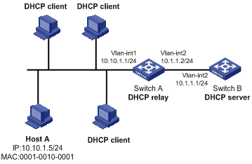
Figure 1-3 Netw Network diagram for DHCP relay agent ork Diagram
Networking and Configuration Requirements
l VLAN-interface 1 on the DHCP relay agent (Switch A) connects to the network where DHCP clients reside. The IP address of VLAN-interface 1 is 10.10.1.1/24 and IP address of VLAN-interface 2 is 10.1.1.2/24 that connects with the DHCP server 10.1.1.1/24.
l Switch A forwards messages so that DHCP clients can obtain IP addresses on subnet 10.10.1.0/24 and related configuration information from the DHCP server.
l Host A uses a static IP address of 10.10.1.5/24, while other hosts obtain dynamic IP addresses.
l Enable IP address match check on Switch A, so that only the clients that have valid IP addresses or obtain IP addresses through DHCP can access the external network.
Applicable Product Matrix
|
Product series |
Software version |
Hardware version |
|
S3610 Series Ethernet Switches |
Release 5301 Release 5303 |
All versions |
|
S5510 Series Ethernet Switches |
Release 5301 Release 5303 |
All versions |
|
S5500-SI Series Ethernet Switches |
Release 1207 |
All versions except S5500-20TP-SI |
|
Release 1301 |
S5500-20TP-SI |
|
|
S5500-EI Series Ethernet Switches |
Release 2102 |
All versions |
|
S7500E Series Ethernet Switches |
Release 6100 Release 6300 |
All versions |
|
S3500-EA Series Ethernet Switches |
Release 5303 |
All versions |
Configuration Procedure
# Enable DHCP.
<SwitchA> system-view
[SwitchA] dhcp enable
# Enable the DHCP relay agent on VLAN-interface 1.
[SwitchA] interface vlan-interface 1
[SwitchA-Vlan-interface1] ip address 10.10.1.1 24
[SwitchA-Vlan-interface1] dhcp select relay
[SwitchA-Vlan-interface1] quit
# Add the IP address of the DHCP server to DHCP server group 1 and correlate VLAN-interface 1 to the group.
[SwitchA] dhcp relay server-group 1 ip 10.1.1.1
[SwitchA] interface vlan-interface 1
[SwitchA-Vlan-interface1] dhcp relay server-select 1
[SwitchA-Vlan-interface1] quit
# Configure a static binding between IP address 10.10.1.5/24 and MAC address 0001-0010-0001.
[SwitchA] dhcp relay security static 10.10.1.5 0001-0010-0001
# Enable IP address match check on the DHCP relay agent.
[SwitchA] interface Vlan-interface 1
[SwitchA-Vlan-interface1] dhcp relay address-check enable
[SwitchA-Vlan-interface1] quit
Complete Configuration
#
dhcp relay server-group 1 ip 10.1.1.1
#
interface Vlan-interface1
ip address 10.10.1.1 255.255.255.0
dhcp select relay
dhcp relay server-select 1
dhcp relay address-check enable
#
dhcp enable
#
dhcp relay security static 10.10.1.5 0001-0010-0001
#
Configuration Guidelines
l You also need to perform configurations on the DHCP server. For how to configure the DHCP server, refer to Configuring Dynamic IP Address Allocation.
l The DHCP relay agent and DHCP server are reachable to each other.
l The dhcp relay address-check enable command is independent of other commands of the DHCP relay agent. That is, the IP address match check takes effect when this command is executed, regardless of whether other commands are used.
Configuring DHCP Snooping
For security, a network administrator needs to use the mappings between DHCP clients’ IP addresses obtained from the DHCP server and their MAC addresses.
DHCP snooping records clients’ MAC and IP addresses by reading DHCP-REQUEST and DHCP-ACK messages.
Network Diagram
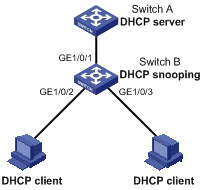
Figure 1-4 Network diagram for DHCP snooping
Networking and Configuration Requirements
l Switch B is connected to a DHCP server through GigabitEthernet 1/0/1, and to two DHCP clients through GigabitEthernet 1/0/2 and GigabitEthernet 1/0/3.
l GigabitEthernet 1/0/1 of Switch B can receive DHCP server responses and the other two cannot.
l Switch B records clients’ IP-to-MAC address bindings in DHCP-REQUEST messages and DHCP-ACK messages received from trusted ports.
l Switch B supports Option 82. After receiving a DHCP request, Switch B adds Option 82 padded in verbose format to the request message and forwards the message to the DHCP server.
Applicable Product Matrix
|
Product series |
Software version |
Hardware version |
|
S3610 Series Ethernet Switches |
Release 5301 Release 5303 |
All versions |
|
S5510 Series Ethernet Switches |
Release 5301 Release 5303 |
All versions |
|
S5500-SI Series Ethernet Switches |
Release 1207 |
All versions except S5500-20TP-SI |
|
Release 1301 |
S5500-20TP-SI |
|
|
S5500-EI Series Ethernet Switches |
Release 2102 |
All versions |
|
S7500E Series Ethernet Switches |
Release 6100 Release 6300 |
All versions |
|
S3500-EA Series Ethernet Switches |
Release 5303 |
All versions |
Note that S5500-SI series Ethernet switches support DHCP snooping and trusted port configurations, but do not support DHCP snooping Option 82.
Configuration Procedure
# Enable DHCP snooping.
<SwitchB> system-view
[SwitchB] dhcp-snooping
# Configure GigabitEthernet 1/0/1 as a trusted port.
[SwitchB] interface gigabitethernet1/0/1
[SwitchB-GigabitEthernet1/0/1] dhcp-snooping trust
[SwitchB-GigabitEthernet1/0/1] quit
# Configure DHCP snooping Option 82 support on GigabitEthernet 1/0/2.
[SwitchB] interface gigabitethernet1/0/2
[SwitchB-GigabitEthernet1/0/2] dhcp-snooping information enable
# Configure the padding format for Option 82 on GigabitEthernet 1/0/2 as verbose.
[SwitchB-GigabitEthernet1/0/2] dhcp-snooping information format verbose node-identifier sysname
[SwitchB-GigabitEthernet1/0/2] quit
# Configure DHCP snooping Option 82 support on GigabitEthernet 1/0/3.
[SwitchB] interface gigabitethernet1/0/3
[SwitchB-GigabitEthernet1/0/3] dhcp-snooping information enable
# Configure the padding format for Option 82 on GigabitEthernet 1/0/3 as verbose.
[SwitchB-GigabitEthernet1/0/3] dhcp-snooping information format verbose node-identifier sysname
Complete Configuration
#
dhcp-snooping
#
interface GigabitEthernet1/0/1
dhcp-snooping trust
#
interface GigabitEthernet1/0/2
dhcp-snooping information enable
dhcp-snooping information format verbose node-identifier sysname
#
interface GigabitEthernet1/0/3
dhcp-snooping information enable
dhcp-snooping information format verbose node-identifier sysname
#
Configuration Guidelines
l The DHCP snooping enabled device does not work if it is between the DHCP relay agent and DHCP server, and it can work when it is between the DHCP clients and relay agent or between the DHCP clients and server.
l The DHCP snooping enabled device cannot be a DHCP server or DHCP relay agent.
l You are not recommended to enable the DHCP client, BOOTP client, and DHCP snooping on the same device. Otherwise, DHCP snooping entries may fail to be generated, or the BOOTP client/DHCP client may fail to obtain an IP address.
l You need to specify the ports connected to authorized DHCP servers as trusted to ensure that DHCP clients can obtain valid IP addresses. A trusted port and a port connected to DHCP clients must be in the same VLAN.
l Configuring both the DHCP snooping and selective QinQ function on the switch is not recommended because it may result in malfunctioning of DHCP snooping.
l DHCP snooping supports no link aggregation. If a Layer 2 Ethernet interface is added into an aggregation group, DHCP snooping configuration on it will not take effect. When the interface is removed from the group, DHCP snooping can take effect.
Configuring DHCP Snooping Option 82 Support
When a DHCP snooping device supporting Option 82 receives a client’s request, it adds Option 82 to the request message and sends it to a DHCP server. Then, the DHCP server can locate the DHCP client and assign an appropriate IP address and other parameters to the client, thus further implementing security control and accounting.
Network Diagram
Figure 1-5 Network diagram for DHCP snooping
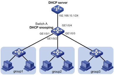
Networking and Configuration Requirements
The working area of a company is divided into three groups, group 1, group 2, and group 3, separately located in three rooms. The company needs to assign different IP address ranges for the groups through a DHCP server. The requirements are:
l Assign IP addresses on the network segment 192.168.10.0/24. The lease duration is twelve hours, DNS server address is 192.168.100.2, and WINS server address is 192.168.100.3.
l Enable DHCP snooping on Switch A, and configure GigabitEthernet 1/0/4 as a DHCP snooping trusted port.
l Group 1, group 2, and group3 are connected to the DHCP snooping device through GigabitEthernet 1/0/1, GigabitEthernet 1/0/2, and GigabitEthernet 1/0/3 respectively.
l Configure DHCP snooping Option 82 support to add port information into Option 82 of DHCP messages.
l Configure the DHCP server to support Option 82. Based on the group information contained in Option 82, the DHCP server assigns 192.168.10.2 through 192.168.10.25 to clients in group 1, 192.168.10.100 through 192.168.10.150 to clients in group 2, and 192.168.10.151 through 192.168.10.200 to clients in group 3.
Applicable Product Matrix
|
Product series |
Software version |
Hardware version |
|
S3610 Series Ethernet Switches |
Release 5301 Release 5303 |
All versions |
|
S5510 Series Ethernet Switches |
Release 5301 Release 5303 |
All versions |
|
S5500-SI Series Ethernet Switches |
Release 1207 |
All versions except S5500-20TP-SI |
|
Release 1301 |
S5500-20TP-SI |
|
|
S5500-EI Series Ethernet Switches |
Release 2102 |
All versions |
|
S7500E Series Ethernet Switches |
Release 6100 Release 6300 |
All versions |
|
S3500-EA Series Ethernet Switches |
Release 5303 |
All versions |
Configuration Procedure
Configuration on Switch A
# Enable DHCP snooping.
<SwitchA> system-view
[SwitchA] dhcp-snooping
# Configure GigabitEthernet 1/0/4 as a DHCP snooping trusted port.
[SwitchA] interface gigabitethernet1/0/4
[SwitchA-GigabitEthernet1/0/4] dhcp-snooping trust
[SwitchA-GigabitEthernet1/0/4] quit
# Configure DHCP snooping Option 82 support on GigabitEthernet 1/0/1, and configure the padding format for Option 82 as normal.
[SwitchA] interface gigabitethernet1/0/1
[SwitchA-GigabitEthernet1/0/1] dhcp-snooping information enable
[SwitchA-GigabitEthernet1/0/1] dhcp-snooping information format normal
[SwitchA-GigabitEthernet1/0/1] quit
# Configure DHCP snooping Option 82 support on GigabitEthernet 1/0/2, and configure the padding format for Option 82 as normal.
[SwitchA] interface gigabitethernet1/0/2
[SwitchA-GigabitEthernet1/0/2] dhcp-snooping information enable
[SwitchA-GigabitEthernet1/0/2] dhcp-snooping informationformat normal
[SwitchA-GigabitEthernet1/0/2] quit
# Configure DHCP snooping Option 82 support on GigabitEthernet 1/0/3, and configure the padding format for Option 82 as normal.
[SwitchA] interface gigabitethernet1/0/3
[SwitchA-GigabitEthernet1/0/3] dhcp-snooping information enable
[SwitchA-GigabitEthernet1/0/3] dhcp-snooping information format normal
[SwitchA-GigabitEthernet1/0/3] quit
Configuration on the DHCP server
![]()
The DHCP server configurations are performed on a Cisco Catalyst 3745 switch with software version IOS 12.3(11)T2. For configurations on other device models or other versions, refer to the corresponding user manuals.
# Configure the IP address for the DHCP server’s interface as 192.168.10.1/24.
Server> enable
Server# configure terminal
Server(config)# interface fastethernet 0/0
Server(config-if)# ip address 192.168.10.1 255.255.255.0
Server(config-if)# exit
# Configure the DHCP server function and enable address allocation based on Option 82.
Server(config)# service dhcp
Server(config)# ip dhcp use class
# Create a DHCP class for clients in group 1 that are connected to the DHCP snooping device through GigabitEthernet 1/0/1, and configure the server to match the VLAN ID and interface number (circuit ID sub-option) in Option 82. The wildcard (*) represents characters that do not need to be matched.
Server(config)# ip dhcp class group1
Server(dhcp-class)# relay agent information
Server(dhcp-class-relayinfo)# relay-information hex 0106000400010001*
Server(dhcp-class-relayinfo)# exit
# Create a DHCP class for clients in group 2 that are connected to the DHCP snooping device through GigabitEthernet 1/0/2, and configure the matching information. The commands are similar to the above. You only need to change the interface number for Option 82 to 2.
Server(config)# ip dhcp class group2
Server(dhcp-class)# relay agent information
Server(dhcp-class-relayinfo)# relay-information hex 0106000400010002*
Server(dhcp-class-relayinfo)# exit
# Create a DHCP class for clients in group 3 that are connected to the DHCP snooping device through GigabitEthernet 1/0/3, and configure the matching information. The commands are similar to the above. You only need to change the interface number for Option 82 to 3.
Server(config)# ip dhcp class group3
Server(dhcp-class)# relay agent information
Server(dhcp-class-relayinfo)# relay-information hex 0106000400010003*
Server(dhcp-class-relayinfo)# exit
# Configure DHCP address pool office (lease duration, gateway, DNS server, and WINS server).
Server(config)# ip dhcp pool office
Server(dhcp-config)# network 192.168.10.0
Server(dhcp-config)# lease 0 12
Server(dhcp-config)# default-router 192.168.10.1
Server(dhcp-config)# dns-server 192.168.100.2
Server(dhcp-config)# netbios-name-server 192.168.100.3
# Specify address ranges for the three DHCP classes.
Server(dhcp-config)# class group1
Server(dhcp-pool-class)# address range 192.168.10.2 192.168.10.25
Server(dhcp-pool-class)# class group2
Server(dhcp-pool-class)# address range 192.168.10.100 192.168.10.150
Server(dhcp-pool-class)# class group3
Server(dhcp-pool-class)# address range 192.168.10.151 192.168.10.200
Complete Configuration
#
dhcp-snooping
#
interface GigabitEthernet1/0/4
dhcp-snooping trust
#
interface GigabitEthernet1/0/1
dhcp-snooping information enable
dhcp-snooping information format normal
#
interface GigabitEthernet1/0/2
dhcp-snooping information enable
dhcp-snooping information format normal
#
interface GigabitEthernet1/0/3
dhcp-snooping information enable
dhcp-snooping information format normal
#
Configuration Guidelines
l You need to enable DHCP snooping before configuring DHCP snooping to support Option 82.
l You are recommended to configure DHCP snooping Option 82 support on the DHCP snooping device closest to DHCP clients, so that the clients can be accurately located.
Configuring DHCP Client
After you specify an interface of the device as a DHCP client, the interface can use DHCP to get information (such as IP address) from the DHCP server, for ease of configuration and centralized management.
Network Diagram
Networking and Configuration Requirements
Configure VLAN-interface 1 on the switch to obtain an IP address through DHCP.
Applicable Product Matrix
|
Product series |
Software version |
Hardware version |
|
S3610 Series Ethernet Switches |
Release 5301 Release 5303 |
All versions |
|
S5510 Series Ethernet Switches |
Release 5301 Release 5303 |
All versions |
|
S5500-SI Series Ethernet Switches |
Release 1207 |
All versions except S5500-20TP-SI |
|
Release 1301 |
S5500-20TP-SI |
|
|
S5500-EI Series Ethernet Switches |
Release 2102 |
All versions |
|
S7500E Series Ethernet Switches |
Release 6100 Release 6300 |
All versions |
|
S3500-EA Series Ethernet Switches |
Release 5303 |
All versions |
Configuration Procedure
# Create VLAN-interface 1 and enter VLAN interface view.
[SwitchB] interface Vlan-interface 1
# Configure VLAN-interface 1 to obtain an IP address through DHCP.
[SwitchB-Vlan-interface1] ip address dhcp-alloc
[SwitchB-Vlan-interface1] quit
Complete Configuration
#
interface Vlan-interface1
ip address dhcp-alloc
#
Configuration Guidelines
You are not recommended to enable both DHCP client and DHCP snooping on the same device. Otherwise, DHCP snooping entries may fail to be generated, or the DHCP client may fail to obtain an IP address.
Configuring Auto-Configuration
With auto-configuration, a device that starts up without any configuration file can automatically obtain a configuration file and execute it, thus implementing simplified network configuration and centralized management. The auto-configuration process is described as follows:
1) When a switch starts up without any configuration file, the system sets an active interface (such as the default VLAN interface) as the DHCP client to request from the DHCP server for parameters, such as an IP address and name of a TFTP server, and the bootfile name.
2) After getting related parameters, the DHCP client will send a TFTP request to obtain the configuration file from the specified TFTP server for system initialization. If the client cannot get such parameters, it will perform system initialization without loading any configuration file.
1.1.1 Network Diagram
Figure 1-6 Network diagram for auto-configuration
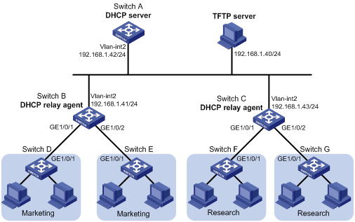
Networking and Configuration Requirements
A company has two departments, marketing department and research&development (R&D) department. The switches directly connected to terminal hosts access the network through different network devices (DHCP relay agents), as shown in Figure 1-6.
l Switch A (DHCP server) assigns IP addresses and other network configuration parameters for hosts of the marketing and R&D departments.
l Run the TFTPD32 software on a host so that it can serve as a TFTP server.
l Switch B serves as both the gateway of the marketing department and a DHCP relay agent. It is connected to the DHCP server and TFTP server through VLAN-interface 2, and connected to Switch D and Switch E through VLAN-interface 3 (with IP address 192.168.2.1/24). Switch D and Switch E are respectively connected to Switch B through VLAN-interface 3.
l Switch C serves as both the gateway of the R&D department and a DHCP relay agent. It is connected to the DHCP server and TFTP server through VLAN-interface 2, and connected to Switch F and Switch G through VLAN-interface 3 (with IP address 192.168.3.1/24). Switch F and Switch G are respectively connected to Switch C through VLAN-interface 3.
To simplify network device management, ensure network security and implement device login and control through telnet, you can configure auto-configuration on the switches directly connected to terminal hosts, so that the switches can automatically obtain configuration files after startup. Through the configuration files, you can:
l Configure the interfaces to obtain IP addresses through DHCP.
l Enable telnet server.
l Create a local user.
l Telnet to the device when authentication is required.
Applicable Product Matrix
|
Product series |
Software version |
Hardware version |
|
S3610 Series Ethernet Switches |
Release 5301 Release 5303 |
All versions |
|
S5510 Series Ethernet Switches |
Release 5301 Release 5303 |
All versions |
|
S5500-EI Series Ethernet Switches |
Release 2102 |
All versions |
|
S3500-EA Series Ethernet Switches |
Release 5303 |
All versions |
Configuration Procedure
![]()
The following configurations are performed and verified in a lab environment. All the parameters of the device before configuration are factory defaults. If you have configured the device, make sure that your configuration does not conflict with the following configuration.
Configuration on Switch A (DHCP server)
# Configure the IP address of VLAN-interface 2.
<SwitchA> system-view
[SwitchA] vlan 2
[SwitchA-vlan2] port gigabitethernet 1/0/1
[SwitchA-vlan2] quit
[SwitchA] interface vlan-interface 2
[SwitchA-Vlan-interface2] ip address 192.168.1.42
[SwitchA-Vlan-interface2] quit
# Enable DHCP.
[SwitchA] dhcp enable
# Configure DHCP address pool market to dynamically assign IP addresses on network segment 192.168.2.0/24 to the marketing department, and specify the TFTP server address, gateway address, and configuration file name.
[SwitchA] dhcp server ip-pool market
[SwitchA-dhcp-pool-market] network 192.168.2.0 24
[SwitchA-dhcp-pool-market] tftp ip-address 192.168.1.40
[SwitchA-dhcp-pool-market] gateway-list 192.168.2.1
[SwitchA-dhcp-pool-market] bootfile-name market.cfg
[SwitchA-dhcp-pool-market] quit
# Configure DHCP address pool research to dynamically assign IP addresses on network segment 192.168.3.0/24 to the R&D department, and specify the TFTP server address, gateway address, and configuration file name.
[SwitchA] dhcp server ip-pool research
[SwitchA-dhcp-pool-research] network 192.168.3.0 24
[SwitchA-dhcp-pool-research] tftp ip-address 192.168.1.40
[SwitchA-dhcp-pool-research] gateway-list 192.168.3.1
[SwitchA-dhcp-pool-research] bootfile-name research.cfg
[SwitchA-dhcp-pool-research] quit
# Configure static routes to the networks through the DHCP relay agents.
[SwitchA] ip route-static 192.168.2.0 24 192.168.1.41
[SwitchA] ip route-static 192.168.3.0 24 192.168.1.43
[SwitchA] quit
Configuration on Switch B (DHCP relay agent)
# Configure IP addresses for VLAN-interface 2 and VLAN-interface 3.
<SwitchB> system-view
[SwitchB] vlan 2
[SwitchB-vlan2] port gigabitethernet 1/0/3
[SwitchB-vlan2] quit
[SwitchB] interface vlan-interface 2
[SwitchB-Vlan-interface2] ip address 192.168.1.41
[SwitchB-Vlan-interface2] quit
[SwitchB] vlan 3
[SwitchB-vlan3] port gigabitethernet 1/0/1
[SwitchB-vlan3] port gigabitethernet 1/0/2
[SwitchB-vlan3] quit
[SwitchB] interface vlan-interface 3
[SwitchB-Vlan-interface3] ip address 192.168.2.1
[SwitchB-Vlan-interface3] quit
# Enable DHCP.
[SwitchB] dhcp enable
# Create DHCP server group 1 and add the IP address of the DHCP server into it.
[SwitchB] dhcp relay server-group 1 ip 192.168.1.42
# Enable DHCP relay agent on VLAN-interface 3.
[SwitchB] interface vlan-interface 3
[SwitchB-Vlan-interface3] dhcp select relay
# Correlate VLAN-interface 3 to DHCP server group 1.
[SwitchB-Vlan-interface3] dhcp relay server-select 1
Configuration on Switch C (DHCP relay agent)
# Configure IP addresses of the VLAN interfaces.
<SwitchC> system-view
[SwitchC] vlan 2
[SwitchC-vlan2] port gigabitethernet 1/0/3
[SwitchC-vlan2] quit
[SwitchC] interface vlan-interface 2
[SwitchC-Vlan-interface2] ip address 192.168.1.43
[SwitchC-Vlan-interface2] quit
[SwitchC] vlan 3
[SwitchC-vlan3] port gigabitethernet 1/0/1
[SwitchC-vlan3] port gigabitethernet 1/0/2
[SwitchC-vlan3] quit
[SwitchC] interface vlan-interface 3
[SwitchC-Vlan-interface3] ip address 192.168.3.1
[SwitchC-Vlan-interface3] quit
# Enable DHCP.
[SwitchC] dhcp enable
# Create DHCP server group 1 and add the IP address of the DHCP server into it.
[SwitchC] dhcp relay server-group 1 ip 192.168.1.42
# Enable DHCP relay agent on VLAN-interface 3.
[SwitchC] interface vlan-interface 3
[SwitchC-Vlan-interface3] dhcp select relay
# Correlate VLAN-interface 3 to DHCP server group 1.
[SwitchC-Vlan-interface3] dhcp relay server-select 1
Configuration on the host (TFTP server)
# Create a configuration file named market.cfg in the directory D:/TFTP server of the host. The content of the configuration file is as follows:
#
sysname Market
#
telnet server enable
#
vlan 3
#
local-user market
password simple market
service-type telnet
level 3
#
interface Vlan-interface3
ip address dhcp-alloc
#
interface GigabitEthernet1/0/1
port access vlan 3
#
user-interface vty 0 4
authentication-mode scheme
user privilege level 3
#
return
# Create a configuration file named research.cfg in the directory D:/TFTP server of the host. The content of the configuration file is as follows:
#
sysname Research
#
telnet server enable
#
vlan 3
#
local-user research
password simple research
service-type telnet
level 3
#
interface Vlan-interface3
ip address dhcp-alloc
#
interface GigabitEthernet1/0/1
port access vlan 3
#
user-interface vty 0 4
authentication-mode scheme
user privilege level 3
#
return
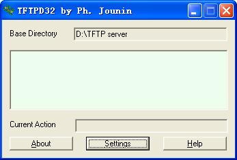
# Run the TFTPD32 software, and then click Settings, as shown in 0.
Figure 1-7 TFTP server configuration page
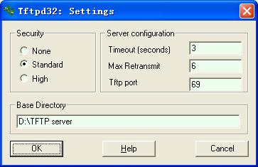
# Specify a path for Base Directory to save the configuration file, and then click OK, as shown in 0.
Figure 1-8 Specify a path to save the configuration file
# Configure routes to network segments 192.168.2.0/24 and 192.168.3.0/24 using the following commands.
route add 192.168.2.0 mask 255.255.255.0 192.168.1.41
route add 192.168.3.0 mask 255.255.255.0 192.168.1.43
Complete Configuration
l Configuration on Switch A
#
vlan 1
#
vlan 2
#
dhcp server ip-pool market
network 192.168.2.0 mask 255.255.255.0
gateway-list 192.168.2.1
bootfile-name market.cfg
tftp-server ip-address 192.168.1.17
#
dhcp server ip-pool research
network 192.168.3.0 mask 255.255.255.0
gateway-list 192.168.3.1
bootfile-name research.cfg
tftp-server ip-address 192.168.1.17
#
interface Vlan-interface2
ip address 192.168.1.42 255.255.255.0
#
interface GigabitEthernet1/0/1
port access vlan 2
#
ip route-static 192.168.2.0 255.255.255.0 192.168.1.41
ip route-static 192.168.3.0 255.255.255.0 192.168.1.43
#
dhcp enable
#
l Configuration on Switch B
#
dhcp relay server-group 1 ip 192.168.1.42
#
vlan 1
#
vlan 2
#
vlan 3
#
interface Vlan-interface2
ip address 192.168.1.41 255.255.255.0
#
interface Vlan-interface3
ip address 192.168.2.1 255.255.255.0
dhcp select relay
dhcp relay server-select 1
#
interface GigabitEthernet1/0/1
port access vlan 3
#
interface GigabitEthernet1/0/2
port access vlan 3
#
interface GigabitEthernet1/0/3
port access vlan 2
#
dhcp enable
#
#
dhcp relay server-group 1 ip 192.168.1.42
#
vlan 1
#
vlan 2
#
vlan 3
#
interface Vlan-interface2
ip address 192.168.1.43 255.255.255.0
#
interface Vlan-interface3
ip address 192.168.3.1 255.255.255.0
dhcp select relay
dhcp relay server-select 1
#
interface GigabitEthernet1/0/1
port access vlan 3
#
interface GigabitEthernet1/0/2
port access vlan 3
#
interface GigabitEthernet1/0/3
port access vlan 2
#
dhcp enable
#
Configuration Guidelines
l To apply auto-configuration on a switch, you need to perform configurations of the DHCP server, DHCP relay agent, TFTP server, and DNS server (optional), and save the configuration file of the switch to the TFTP server.
l The DHCP server needs to assign gateway addresses to clients which then can request for TFTP and DNS services from other subnets.
l Before rebooting a switch, you are recommended to connect only one interface to the network to ensure normal operation of the auto-configuration function.
l After the switch obtains the configuration file, it only executes the configuration file, rather than saving it locally. When the switch is rebooted, it needs to obtain the configuration file again.