- Table of Contents
-
- H3C Low-End and Mid-Range Ethernet Switches Configuration Examples(V1.01)
- 00-1Cover
- 01-Login Configuration Guide
- 02-VLAN Configuration Guide
- 03-GVRP Configuration Guide
- 04-Voice VLAN Configuration Guide
- 05-IP Addressing and Performance Configuration Guide
- 06-QinQ Configuration Guide
- 07-BPDU Tunnel Configuration Guide
- 08-VLAN Mapping Configuration Guide
- 09-MAC Address Table Management Configuration Guide
- 10-Link Aggregation Configuration Guide
- 11-IP Source Guard Configuration Guide
- 12-DLDP Configuration Guide
- 13-MSTP Configuration Guide
- 14-IPv4 Routing Configuration Guide
- 15-IPv6 Configuration Guide
- 16-IPv6 Routing Configuration Guide
- 17-IPv4 Multicast Configuration Guide
- 18-IPv6 Multicast Configuration Examples
- 19-802.1x Configuration Guide
- 20-AAA Configuration Guide
- 21-MAC Authentication Configuration Guide
- 22-Portal Configuration Guide
- 23-ARP Configuration Guide
- 24-DHCP Configuration Guide
- 25-ACL Configuration Guide
- 26-QoS Configuration Guide
- 27-Port Mirroring Configuration Guide
- 28-Cluster Management Configuration Guide
- 29-SNMP-RMON Configuration Guide
- 30-NTP Configuration Guide
- 31-FTP-TFTP Configuration Guide
- 32-UDP Helper Configuration Guide
- 33-Information Center Configuration Guide
- 34-DNS Configuration Guide
- 35-File System Management Configuration Guide
- 36-Remote Upgrade Configuration Guide
- 37-NQA Configuration Guide
- 38-VRRP Configuration Guide
- 39-SSH Configuration Guide
- 40-Port Security Configuration Guide
- 41-Port Isolation Configuration Guide
- 42-LLDP Configuration Guide
- 43-MCE Configuration Guide
- 44-PoE Configuration Guide
- 45-OAM Configuration Guide
- 46-Connectivity Fault Detection Configuration Guide
- 47-RRPP Configuration Guide
- 48-sFlow Configuration Guide
- 49-SSL-HTTPS Configuration Guide
- 50-PKI Configuration Guide
- 51-Track Configuration Guide
- 52-EPON-OLT Configuration Guide
- 53-Smart Link Configuration Guide
- 54-MPLS Configuration Guide
- Related Documents
-
| Title | Size | Download |
|---|---|---|
| 42-LLDP Configuration Guide | 78.8 KB |
Table of Contents
Networking and Configuration Requirements
CDP-Compatible LLDP Configuration Example
LLDP
Configuring LLDP
Network Diagram
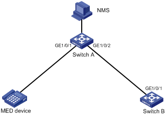
Figure 1-1 Network diagram for LLDP configuration
Networking and Configuration Requirements
l As shown in Figure 1-1, connect NMS to Switch A over the Ethernet; and connect Switch A to the MED device and Switch B through GigabitEthernet 1/0/1 and GigabitEthernet 1/0/2 respectively.
Applicable Product Matrix
|
Product series |
Software version |
Hardware version |
|
S5500-EI series Ethernet switches |
Release 2102 |
All versions |
|
S7500E series Ethernet switches |
Release 6100 |
All versions |
Configuration Procedure
1) Configure Switch A
# Enter system view:
<SwitchA> system-view
# Enable LLDP globally.
[SwitchA] lldp enable
# Enable LLDP on interfaces GigabitEthernet 1/0/1 and GigabitEthernet 1/0/2 respectively and set the LLDP work mode to rx.
[SwitchA] interface GigabitEthernet1/0/1
[SwitchA-GigabitEthernet1/0/1] lldp enable
[SwitchA-GigabitEthernet1/0/1] lldp admin-status rx
[SwitchA-GigabitEthernet1/0/1] quit
[SwitchA] interface GigabitEthernet1/0/2
[SwitchA-GigabitEthernet1/0/2] lldp enable
[SwitchA-GigabitEthernet1/0/2] lldp admin-status rx
[SwitchA-GigabitEthernet1/0/2] quit
2) Configure Switch B
# Enter system view:
<SwitchB> system-view
# Enable LLDP globally.
[SwitchB] lldp enable
# Enable LLDP on interface GigabitEthernet 1/0/1 and set the LLDP work mode to tx.
[SwitchB] interface GigabitEthernet1/0/1
[SwitchB-GigabitEthernet1/0/1] lldp enable
[SwitchB-GigabitEthernet1/0/1] lldp admin-status tx
3) Verify the configuration
# Display global and port-level LLDP status on Switch A.
<SwitchA> display lldp status
Global status of LLDP : Enable
The current number of neighbors : 2
Neighbor information last changed time : 0 days, 0 hours, 4 minutes, 40 seconds
Transmit interval : 30s
Hold multiplier : 4
Reinit delay : 2s
Transmit delay : 2s
Trap interval : 5s
Fast start times : 3
Port 0 [GigabitEthernet1/0/1] :
Port status of LLDP : Enable
Admin status : Rx_Only
Trap flag : No
Roll time : 0s
Number of neighbors : 1
Number of MED neighbors : 1
Number of sent optional TLV : 0
Number of received unknown TLV : 0
Port 1 [GigabitEthernet1/0/2] :
Port status of LLDP : Enable
Admin status : Rx_Only
Trap flag : No
Roll time : 0s
Number of neighbors : 1
Number of MED neighbors : 0
Number of sent optional TLV : 0
Number of received unknown TLV : 3
……(information for other ports omitted)
# By default, the telnet terminal monitor is disabled. To display the log information generated by LLDP status changes on NMS, enable the terminal monitor.
<SwitchA> terminal monitor
# Tear down the link between Switch A and Switch B, and enable the terminal monitor to display the following log information on Switch A (that on Switch B is similar):
%Nov 21 11:38:42:86 2007 H3C IFNET/4/LINK UPDOWN: GigabitEthernet1/0/2: link status is DOWN
%Nov 21 11:40:26:846 2007 H3C LLDP/2/AGEOUTREM:Port GigabitEthernet1/0/2 (IfIndex 9437201):Neighbor aged out, chassis ID: 000f-e272-8351, port ID: GigabitEthernet1/0/1.
# Display global and port-level LLDP status on Switch A.
<SwitchA> display lldp status
Global status of LLDP : Enable
The current number of neighbors : 1
Neighbor information last changed time : 0 days, 0 hours, 5 minutes, 20 seconds
Transmit interval : 30s
Hold multiplier : 4
Reinit delay : 2s
Transmit delay : 2s
Trap interval : 5s
Fast start times : 3
Port 0 [GigabitEthernet1/0/1] :
Port status of LLDP : Enable
Admin status : Rx_Only
Trap flag : No
Roll time : 0s
Number of neighbors : 1
Number of MED neighbors : 1
Number of sent optional TLV : 0
Number of received unknown TLV : 5
Port 1 [GigabitEthernet1/0/2] :
Port status of LLDP : Enable
Admin status : Rx_Only
Trap flag : No
Roll time : 0s
Number of neighbors : 0
Number of MED neighbors : 0
Number of sent optional TLV : 0
Number of received unknown TLV : 0
……(information for other ports omitted)
Complete Configuration
l Configuration on Switch A
#
interface GigabitEthernet1/0/1
lldp admin-status rx
#
interface GigabitEthernet1/0/2
lldp admin-status rx
l Configuration on Switch B
#
interface GigabitEthernet1/0/1
lldp admin-status tx
Configuration Guidelines
To display the log information generated by neighbor status changes on the terminal monitor, make sure that the terminal monitor (through the terminal monitor command), log information switch (through the terminal logging command), and information center (through the info-center enable command) are enabled. The example in this document involves the terminal monitor configuration only, since the telnet terminal monitor of the S5500-EI is disabled while the log information switch and the information center are enabled by default. For details, refer to the Information Center module in the Operation Manual.
CDP-Compatible LLDP Configuration Example
Network diagram
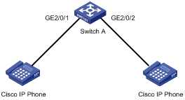
Figure 1-2 Network diagram for LLDP compatible with CDP configuration
Network requirements
l GigabitEthernet 2/0/1 and GigabitEthernet 2/0/2 of Switch A are each connected to a Cisco IP phone.
l Configure voice VLAN 2 on Switch A. Enable CDP compatibility of LLDP on Switch A to allow the Cisco IP phones to automatically configure the voice VLAN, thus confining their voice traffic within the voice VLAN to be isolated from other types of traffic.
Applicable Product Matrix
|
Product series |
Software version |
Hardware version |
|
S7500E series Ethernet switches |
Release 6300 |
All versions |
Configuration Procedure
1) Configure the voice VLAN on Switch A
# Create VLAN 2.
<SwitchA> system-view
[SwitchA] vlan 2
[SwitchA-vlan2] quit
# Enable the voice VLAN feature globally and configure VLAN 2 as the voice VLAN.
[SwitchA] voice vlan 2 enable
# Enable the voice VLAN feature on GigabitEthernet 2/0/1 and GigabitEthernet 2/0/2.
[SwitchA] interface GigabitEthernet 2/0/1
[SwitchA-GigabitEthernet2/0/1] voice vlan enable
[SwitchA-GigabitEthernet2/0/1] quit
[SwitchA] interface GigabitEthernet 2/0/2
[SwitchA-GigabitEthernet2/0/2] voice vlan enable
[SwitchA-GigabitEthernet2/0/2] quit
2) Configure CDP-compatible LLDP on Switch A.
# Enable LLDP globally.
[SwitchA] lldp enable
# Enable LLDP to be compatible with CDP globally.
[SwitchA] lldp compliance cdp
# Enable LLDP, configure LLDP to operate in TxRx mode, and configure CDP-compatible LLDP to operate in TxRx mode on GigabitEthernet 2/0/1 and GigabitEthernet 2/0/2.
[SwitchA] interface GigabitEthernet 2/0/1
[SwitchA-GigabitEthernet2/0/1] lldp enable
[SwitchA-GigabitEthernet2/0/1] lldp admin-status txrx
[SwitchA-GigabitEthernet2/0/1] lldp compliance admin-status cdp txrx
[SwitchA-GigabitEthernet2/0/1] quit
[SwitchA] interface GigabitEthernet 2/0/2
[SwitchA-GigabitEthernet2/0/2] lldp enable
[SwitchA-GigabitEthernet2/0/2] lldp admin-status txrx
[SwitchA-GigabitEthernet2/0/2] lldp compliance admin-status cdp txrx
[SwitchA-GigabitEthernet2/0/2] quit
3) Verify the configuration
# Display the neighbor information on Switch A.
[SwitchA] display lldp neighbor-information
CDP neighbor-information of port 97[GigabitEthernet2/0/1]:
CDP neighbor index : 1
Chassis ID : SEP00141CBCDBFE
Port ID : Port 1
Sofrware version : P0030301MFG2
Platform : Cisco IP Phone 7960
Duplex : Full
CDP neighbor-information of port 98[GigabitEthernet2/0/2]:
CDP neighbor index : 2
Chassis ID : SEP00141CBCDBFF
Port ID : Port 1
Sofrware version : P0030301MFG2
Platform : Cisco IP Phone 7960
Duplex : Full
Complete Configuration
#
voice vlan 2 enable
#
lldp compliance cdp
#
vlan 2
#
interface GigabitEthernet2/0/1
port access vlan 2
undo voice vlan mode auto
voice vlan enable
lldp compliance admin-status cdp txrx
#
interface GigabitEthernet2/0/2
port access vlan 2
undo voice vlan mode auto
voice vlan enable
lldp compliance admin-status cdp txrx
#
Configuration Guidelines
l For detailed information about voice VLAN, refer to VLAN Configuration Guide.
l LLDP is enabled on the port connected to an IP phone and is configured to operate in TxRx mode on the port.
l As the maximum TTL allowed by CDP is 255 seconds, your TTL configuration, that is, the product of the TTL multiplier and the LLDPDU sending interval, must be less than 255 seconds for CDP-compatible LLDP to work properly with Cisco IP phones.