- Table of Contents
-
- H3C Low-End and Mid-Range Ethernet Switches Configuration Examples(V1.01)
- 00-1Cover
- 01-Login Configuration Guide
- 02-VLAN Configuration Guide
- 03-GVRP Configuration Guide
- 04-Voice VLAN Configuration Guide
- 05-IP Addressing and Performance Configuration Guide
- 06-QinQ Configuration Guide
- 07-BPDU Tunnel Configuration Guide
- 08-VLAN Mapping Configuration Guide
- 09-MAC Address Table Management Configuration Guide
- 10-Link Aggregation Configuration Guide
- 11-IP Source Guard Configuration Guide
- 12-DLDP Configuration Guide
- 13-MSTP Configuration Guide
- 14-IPv4 Routing Configuration Guide
- 15-IPv6 Configuration Guide
- 16-IPv6 Routing Configuration Guide
- 17-IPv4 Multicast Configuration Guide
- 18-IPv6 Multicast Configuration Examples
- 19-802.1x Configuration Guide
- 20-AAA Configuration Guide
- 21-MAC Authentication Configuration Guide
- 22-Portal Configuration Guide
- 23-ARP Configuration Guide
- 24-DHCP Configuration Guide
- 25-ACL Configuration Guide
- 26-QoS Configuration Guide
- 27-Port Mirroring Configuration Guide
- 28-Cluster Management Configuration Guide
- 29-SNMP-RMON Configuration Guide
- 30-NTP Configuration Guide
- 31-FTP-TFTP Configuration Guide
- 32-UDP Helper Configuration Guide
- 33-Information Center Configuration Guide
- 34-DNS Configuration Guide
- 35-File System Management Configuration Guide
- 36-Remote Upgrade Configuration Guide
- 37-NQA Configuration Guide
- 38-VRRP Configuration Guide
- 39-SSH Configuration Guide
- 40-Port Security Configuration Guide
- 41-Port Isolation Configuration Guide
- 42-LLDP Configuration Guide
- 43-MCE Configuration Guide
- 44-PoE Configuration Guide
- 45-OAM Configuration Guide
- 46-Connectivity Fault Detection Configuration Guide
- 47-RRPP Configuration Guide
- 48-sFlow Configuration Guide
- 49-SSL-HTTPS Configuration Guide
- 50-PKI Configuration Guide
- 51-Track Configuration Guide
- 52-EPON-OLT Configuration Guide
- 53-Smart Link Configuration Guide
- 54-MPLS Configuration Guide
- Related Documents
-
| Title | Size | Download |
|---|---|---|
| 12-DLDP Configuration Guide | 40.22 KB |
Overview
DLDP Introduction
Sometimes, unidirectional links may appear in networks. On a unidirectional link, one end can receive packets from the other end but the other end cannot. Unidirectional links result in problems such as loops in an STP-enabled network.
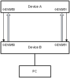
As for fiber links, two kinds of unidirectional links exist. One occurs when fibers are cross-connected, as shown in 0. The other occurs when one end of a fiber is not connected or one fiber of a fiber pair gets disconnected, as illustrated by the hollow arrows in 0.
Figure 1-1 Unidirectional fiber link: cross-connected fiber
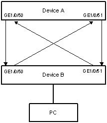
Figure 1-2 Unidirectional fiber link: fiber not connected or disconnected
Device Link Detection Protocol (DLDP) can detect the link status of a fiber cable or twisted pair. On detecting a unidirectional link, DLDP can shut down the related port automatically or prompt users to take measures as configured to avoid network problems.
Configuring DLDP
Network Diagram
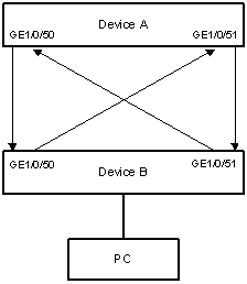
Figure 1-3 Network diagram for DLDP configuration
Networking and Configuration Requirements
l Device A and Device B are connected through two fiber pairs, in which two fibers are cross-connected, as shown in Figure 1-3.
l It is desired that the unidirectional links can be disconnected on being detected; and the ports shut down by DLDP can be restored after the fiber connections are corrected.
Applicable Product Matrix
|
Product series |
Software version |
Hardware version |
|
S3610 series Ethernet switches |
Release 5301 Release 5303 |
All versions |
|
S5510 series Ethernet switches |
Release 5301 Release 5303 |
All versions |
|
S5500-EI series Ethernet switches |
Release 2102 |
All versions |
|
S7500E series Ethernet switches |
Release 6300 |
All versions |
|
S3500-EA series Ethernet switches |
Release 5303 |
All versions |
Configuration Procedure
1) Configuration on Device A:
# Enable DLDP on GigabitEthernet 1/0/50 and GigabitEthernet 1/0/51.
<DeviceA> system-view
[DeviceA] interface gigabitethernet 1/0/50
[DeviceA-GigabitEthernet1/0/50] dldp enable
[DeviceA-GigabitEthernet1/0/50] quit
[DeviceA] interface gigabitethernet 1/0/51
[DeviceA-GigabitEthernet1/0/51] dldp enable
[DeviceA-GigabitEthernet1/0/51] quit
# Set the interval for sending Advertisement packets to 6 seconds.
[DeviceA] dldp interval 6
# Set the DelayDown timer to 2 seconds.
[DeviceA] dldp delaydown-timer 2
# Set the DLDP mode to enhanced mode.
[DeviceA] dldp work-mode enhance
# Set the port shutdown mode to auto mode.
[DeviceA] dldp unidirectional-shutdown auto
# Enable DLDP globally.
[DeviceA] dldp enable
# Display DLDP information.
[DeviceA] display dldp
DLDP global status : enable
DLDP interval : 6s
DLDP work-mode : enhance
DLDP authentication-mode : none
DLDP unidirectional-shutdown : auto
DLDP delaydown-timer : 2s
The number of enabled ports is 2.
Interface GigabitEthernet1/0/50
DLDP port state : disable
DLDP link state : down
The neighbor number of the port is 0.
Interface GigabitEthernet1/0/51
DLDP port state : disable
DLDP link state : down
The neighbor number of the port is 0.
The output information indicates that both GigabitEthernet1/0/50 and GigabitEthernet1/0/51 are in Disable state and the links are down, which means unidirectional links are detected and the two ports are thus shut down.
# Reset DLDP state for the ports shut down by DLDP.
[DeviceA] dldp reset
2) Configuration on Device B:
The configuration on Device B is the same as that on Device A and is thus omitted.
![]()
If two fibers are cross-connected, all the four ports involved will be shut down by DLDP.
Complete Configuration
l Device A
#
dldp enable
dldp interval 6
dldp work-mode enhance
dldp delaydown-timer 2
#
interface GigabitEthernet1/0/50
dldp enable
#
interface GigabitEthernet1/0/51
dldp enable
l Device B
The complete configuration on Device B is the same as that on Device A and is thus omitted.
Configuration Guidelines
1) DLDP can detect unidirectional links only after all links are connected. Therefore, before enabling DLDP, make sure that optical fibers or copper twisted pairs are connected.
2) DLDP takes effect only when it is enabled both globally and on a port.
3) Set the interval for sending Advertisement packets to a value not longer than one-third of the STP convergence time. If the interval is too long, STP loops may occur before unidirectional links are torn down, and it takes a long time for the device to detect unidirectional links, thus causing more traffic forwarding errors; if the interval is too short, unnecessary Advertisement packets can be generated to consume bandwidth. Therefore, you are recommended to use the default value.
4) To enable DLDP to operate properly, make sure the DLDP authentication modes and the passwords of the two sides of a link are the same.
5) Destination MAC addresses of DLDP packets fall into two types: class A and class B, which is dependent on the software versions running on the device. To ensure that DLDP operates properly, interconnected devices must use destination MAC addresses of the same class. Table 1-1 describes the software versions using class-A destination MAC addresses (new addresses). The remaining versions use class-B destination MAC addresses.
Table 1-1 Software versions using class-A destination MAC addresses
|
Product series |
Software versions |
|
S3600 series Ethernet switches |
Release 1510P06 and later |
|
S5600 series Ethernet switches |
Release 1510P06 and later |
|
S5100 series Ethernet switches |
Release 2200 and later |
| S3610 series Ethernet switches |
All versions |
|
S5510 series Ethernet switches |
All versions |
|
S5500-EI series Ethernet switches |
All versions |