- Table of Contents
-
- H3C Low-End and Mid-Range Ethernet Switches Configuration Examples(V1.01)
- 00-1Cover
- 01-Login Configuration Guide
- 02-VLAN Configuration Guide
- 03-GVRP Configuration Guide
- 04-Voice VLAN Configuration Guide
- 05-IP Addressing and Performance Configuration Guide
- 06-QinQ Configuration Guide
- 07-BPDU Tunnel Configuration Guide
- 08-VLAN Mapping Configuration Guide
- 09-MAC Address Table Management Configuration Guide
- 10-Link Aggregation Configuration Guide
- 11-IP Source Guard Configuration Guide
- 12-DLDP Configuration Guide
- 13-MSTP Configuration Guide
- 14-IPv4 Routing Configuration Guide
- 15-IPv6 Configuration Guide
- 16-IPv6 Routing Configuration Guide
- 17-IPv4 Multicast Configuration Guide
- 18-IPv6 Multicast Configuration Examples
- 19-802.1x Configuration Guide
- 20-AAA Configuration Guide
- 21-MAC Authentication Configuration Guide
- 22-Portal Configuration Guide
- 23-ARP Configuration Guide
- 24-DHCP Configuration Guide
- 25-ACL Configuration Guide
- 26-QoS Configuration Guide
- 27-Port Mirroring Configuration Guide
- 28-Cluster Management Configuration Guide
- 29-SNMP-RMON Configuration Guide
- 30-NTP Configuration Guide
- 31-FTP-TFTP Configuration Guide
- 32-UDP Helper Configuration Guide
- 33-Information Center Configuration Guide
- 34-DNS Configuration Guide
- 35-File System Management Configuration Guide
- 36-Remote Upgrade Configuration Guide
- 37-NQA Configuration Guide
- 38-VRRP Configuration Guide
- 39-SSH Configuration Guide
- 40-Port Security Configuration Guide
- 41-Port Isolation Configuration Guide
- 42-LLDP Configuration Guide
- 43-MCE Configuration Guide
- 44-PoE Configuration Guide
- 45-OAM Configuration Guide
- 46-Connectivity Fault Detection Configuration Guide
- 47-RRPP Configuration Guide
- 48-sFlow Configuration Guide
- 49-SSL-HTTPS Configuration Guide
- 50-PKI Configuration Guide
- 51-Track Configuration Guide
- 52-EPON-OLT Configuration Guide
- 53-Smart Link Configuration Guide
- 54-MPLS Configuration Guide
- Related Documents
-
| Title | Size | Download |
|---|---|---|
| 16-IPv6 Routing Configuration Guide | 402.85 KB |
Table of Contents
1 IPv6 Routing Configuration Guide
Configuring an IPv6 Static Route
Networking and Configuration Requirements
Networking and Configuration Requirements
Configuring RIPng Route Redistribution
Networking and Configuration Requirements
Configuring IPv6 RIPng over IPv4 Tunnel
Networking and Configuration Requirements
Networking and Configuration Requirements
Configuring OSPFv3 Route Redistribution
Networking and Configuration Requirements
Networking and Configuration Requirements
Networking and Configuration Requirements
Networking and Configuration Requirements
Configuring IPv6 BGP Route Reflector
Networking and Configuration Requirements
Configuring Route Policy Application in IPv6 Route Redistribution
Networking and Configuration Requirements
Configuring an IPv6 Static Route
Static routes are manually configured. They work well in simple networks. Configuring and using them properly can improve the performance of networks and guarantee enough bandwidth for important applications.
However, static routes also have shortcomings: any topology changes could result in unavailable routes, requiring the network administrator to manually configure and modify the static routes.
Network Diagram
Figure 1-1 Network diagram for IPv6 static route configuration
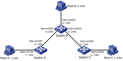
Networking and Configuration Requirements
With IPv6 static routes configured, all hosts and switches can communicate with each other.
Applicable Product Matrix
|
Product series |
Software version |
Hardware version |
|
S3610 Series Ethernet Switches |
Release 5301 Release 5303 |
All versions |
|
S5510 Series Ethernet Switches |
Release 5301 Release 5303 |
All versions |
|
S5500-SI Series Ethernet Switches |
Release 1207 |
All versions, except S5500-20TP-SI |
|
Release 1301 |
S5500-20TP-SI |
|
|
S5500-EI Series Ethernet Switches |
Release 2102 |
All versions |
|
S7500E Series Ethernet Switches |
Release 6100 Release 6300 |
All versions |
Configuration Procedure
1) Configure the IPv6 addresses of all VLAN interfaces (omitted)
2) Configure IPv6 static routes.
# Configure the default IPv6 static route on Switch A.
<SwitchA> system-view
[SwitchA] ipv6
[SwitchA] ipv6 route-static :: 0 4::2
# Configure two IPv6 static routes on Switch B.
<SwitchB> system-view
[SwitchB] ipv6
[SwitchB] ipv6 route-static 1:: 64 4::1
[SwitchB] ipv6 route-static 3:: 64 5::1
# Configure the default IPv6 static route on Switch C.
<SwitchC> system-view
[SwitchC] ipv6
[SwitchC] ipv6 route-static :: 0 5::2
3) Configure the IPv6 addresses of hosts and gateways.
Configure the IPv6 addresses of all the hosts based upon the network diagram, configure the default gateway of Host A as 1::1, that of Host B as 2::1, and that of Host C as 3::1.
4) Display configuration information
# Display the IPv6 routing table of Switch A.
[SwitchA] display ipv6 routing-table
Routing Table :
Destinations : 7 Routes : 7
Destination: ::/0 Protocol : Static
NextHop : 4::2 Preference: 60
Interface : Vlan200 Cost : 0
Destination: ::1/128 Protocol : Direct
NextHop : ::1 Preference: 0
Interface : InLoop0 Cost : 0
Destination: 1::/64 Protocol : Direct
NextHop : 1::1 Preference: 0
Interface : Vlan100 Cost : 0
Destination: 1::1/128 Protocol : Direct
NextHop : ::1 Preference: 0
Interface : InLoop0 Cost : 0
Destination: 4::/64 Protocol : Direct
NextHop : 4::1 Preference: 0
Interface : Vlan200 Cost : 0
Destination: 4::1/128 Protocol : Direct
NextHop : ::1 Preference: 0
Interface : InLoop0 Cost : 0
Destination: FE80::/10 Protocol : Direct
NextHop : :: Preference: 0
Interface : NULL0 Cost : 0
# Verify the connectivity with the ping command.
[SwitchA] ping ipv6 3::1
PING 3::1 : 56 data bytes, press CTRL_C to break
Reply from 3::1
bytes=56 Sequence=1 hop limit=254 time = 63 ms
Reply from 3::1
bytes=56 Sequence=2 hop limit=254 time = 62 ms
Reply from 3::1
bytes=56 Sequence=3 hop limit=254 time = 62 ms
Reply from 3::1
bytes=56 Sequence=4 hop limit=254 time = 63 ms
Reply from 3::1
bytes=56 Sequence=5 hop limit=254 time = 63 ms
--- 3::1 ping statistics ---
5 packet(s) transmitted
5 packet(s) received
0.00% packet loss
round-trip min/avg/max = 62/62/63 ms
Complete Configuration
l Configure Switch A.
#
ipv6
#
ipv6 route-static :: 0 4::2
#
l Configure Switch B.
#
ipv6
#
ipv6 route-static 1:: 64 4::1
ipv6 route-static 3:: 64 5::1
#
l Configure Switch C.
#
ipv6
#
ipv6 route-static :: 0 5::2
#
Configuration Guidelines
When configuring a static route, you can specify the output interface. If the output interface is a VLAN interface, the next hop address must be specified.
Configuring IPv6 RIPng
RIP next generation (RIPng) is an extension of RIP-2 for IPv4. Most RIP concepts are applicable in RIPng.
RIPng for IPv6 made the following changes to RIP:
l UDP port number: RIPng uses UDP port 521 for sending and receiving routing information.
l Multicast address: RIPng uses FF02:9 as the link-local multicast address.
l Destination Prefix: 128-bit destination address prefix.
l Next hop: 128-bit IPv6 address.
l Source address: RIPng uses FE80::/10 as the link-local source address
Network Diagram
Figure 1-2 Network diagram for RIPng configuration
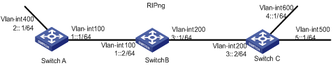
Networking and Configuration Requirements
As shown in the figure above, all switches run RIPng. Configure Switch B to filter the route (3::/64) learned from Switch C so that the route will not be added to the routing table of Switch B and Switch B will not forward it to Switch A.
Applicable Product Matrix
|
Product series |
Software version |
Hardware version |
|
S3610 Series Ethernet Switches |
Release 5301 Release 5303 |
All versions |
|
S5510 Series Ethernet Switches |
Release 5301 Release 5303 |
All versions |
|
S5500-SI Series Ethernet Switches |
Release 1207 |
All versions, except S5500-20TP-SI |
|
Release 1301 |
S5500-20TP-SI |
|
|
S5500-EI Series Ethernet Switches |
Release 2102 |
All versions |
|
S7500E Series Ethernet Switches |
Release 6100 Release 6300 |
All versions |
Configuration Procedure
1) Configure the IPv6 address for each interface (omitted)
2) Configure basic RIPng functions.
# Configure Switch A.
<SwitchA> system-view
[SwitchA] ipv6
[SwitchA] ripng 1
[SwitchA-ripng-1] quit
[SwitchA] interface vlan-interface 100
[SwitchA-Vlan-interface100] ripng 1 enable
[SwitchA-Vlan-interface100] quit
[SwitchA] interface vlan-interface 400
[SwitchA-Vlan-interface400] ripng 1 enable
[SwitchA-Vlan-interface400] quit
# Configure Switch B.
<SwitchB> system-view
[SwitchB] ipv6
[SwitchB] ripng 1
[SwitchB-ripng-1] quit
[SwitchB] interface vlan-interface 200
[SwitchB-Vlan-interface200] ripng 1 enable
[SwitchB-Vlan-interface200] quit
[SwitchB] interface vlan-interface 100
[SwitchB-Vlan-interface100] ripng 1 enable
[SwitchB-Vlan-interface100] quit
# Configure Switch C.
<SwitchC> system-view
[SwitchC] ipv6
[SwitchC] ripng 1
[SwitchC-ripng-1] quit
[SwitchC] interface vlan-interface 200
[SwitchC-Vlan-interface200] ripng 1 enable
[SwitchC-Vlan-interface200] quit
[SwitchC] interface vlan-interface 500
[SwitchC-Vlan-interface500] ripng 1 enable
[SwitchC-Vlan-interface500] quit
[SwitchC] interface vlan-interface 600
[SwitchC-Vlan-interface600] ripng 1 enable
[SwitchC-Vlan-interface600] quit
# Display the routing table of Switch B.
[SwitchB] display ripng 1 route
Route Flags: A - Aging, S - Suppressed, G - Garbage-collect
----------------------------------------------------------------
Peer FE80::20F:E2FF:FE23:82F5 on Vlan-interface100
Dest 1::/64,
via FE80::20F:E2FF:FE23:82F5, cost 1, tag 0, A, 6 Sec
Dest 2::/64,
via FE80::20F:E2FF:FE23:82F5, cost 1, tag 0, A, 6 Sec
Peer FE80::20F:E2FF:FE00:100 on Vlan-interface200
Dest 3::/64,
via FE80::20F:E2FF:FE00:100, cost 1, tag 0, A, 11 Sec
Dest 4::/64,
via FE80::20F:E2FF:FE00:100, cost 1, tag 0, A, 11 Sec
Dest 5::/64,
via FE80::20F:E2FF:FE00:100, cost 1, tag 0, A, 11 Sec
# Display the RIPng routing table of Switch A.
[SwitchA] display ripng 1 route
Route Flags: A - Aging, S - Suppressed, G - Garbage-collect
----------------------------------------------------------------
Peer FE80::200:2FF:FE64:8904 on Vlan-interface100
Dest 1::/64,
via FE80::200:2FF:FE64:8904, cost 1, tag 0, A, 31 Sec
Dest 4::/64,
via FE80::200:2FF:FE64:8904, cost 2, tag 0, A, 31 Sec
Dest 5::/64,
via FE80::200:2FF:FE64:8904, cost 2, tag 0, A, 31 Sec
Dest 3::/64,
via FE80::200:2FF:FE64:8904, cost 1, tag 0, A, 31 Sec
3) Configure Switch B to filter incoming and outgoing routes.
[SwitchB] acl ipv6 number 2000
[SwitchB-acl6-basic-2000] rule deny source 3::/64
[SwitchB-acl6-basic-2000] rule permit
[SwitchB-acl6-basic-2000] quit
[SwitchB] ripng 1
[SwitchB-ripng-1] filter-policy 2000 import
[SwitchB-ripng-1] filter-policy 2000 export
[SwitchB-ripng-1] quit
# Display RIPng routing tables of Switch B and Switch A.
[SwitchB] display ripng 1 route
Route Flags: A - Aging, S - Suppressed, G - Garbage-collect
----------------------------------------------------------------
Peer FE80::20F:E2FF:FE23:82F5 on Vlan-interface100
Dest 1::/64,
via FE80::20F:E2FF:FE23:82F5, cost 1, tag 0, A, 2 Sec
Dest 2::/64,
via FE80::20F:E2FF:FE23:82F5, cost 1, tag 0, A, 2 Sec
Peer FE80::20F:E2FF:FE00:100 on Vlan-interface200
Dest 4::/64,
via FE80::20F:E2FF:FE00:100, cost 1, tag 0, A, 5 Sec
Dest 5::/64,
via FE80::20F:E2FF:FE00:100, cost 1, tag 0, A, 5 Sec
[SwitchA] display ripng 1 route
Route Flags: A - Aging, S - Suppressed, G - Garbage-collect
----------------------------------------------------------------
Peer FE80::20F:E2FF:FE00:1235 on Vlan-interface100
Dest 1::/64,
via FE80::20F:E2FF:FE00:1235, cost 1, tag 0, A, 2 Sec
Dest 4::/64,
via FE80::20F:E2FF:FE00:1235, cost 2, tag 0, A, 2 Sec
Dest 5::/64,
via FE80::20F:E2FF:FE00:1235, cost 2, tag 0, A, 2 Sec
Complete Configuration
l Configure Switch A.
#
ipv6
#
vlan 100
#
vlan 400
#
interface Vlan-interface100
ipv6 address 1::1/64
ripng 1 enable
#
interface Vlan-interface400
ipv6 address 2::1/64
ripng 1 enable
#
ripng 1
#
l Configure Switch B.
#
ipv6
#
vlan 100
#
vlan 200
#
acl ipv6 number 2000
rule 0 deny source 3::/64
rule 5 permit
#
interface Vlan-interface100
ipv6 address 1::2/64
ripng 1 enable
#
interface Vlan-interface200
ipv6 address 3::1/64
ripng 1 enable
#
ripng 1
filter-policy 2000 import
filter-policy 2000 export
#
l Configure Switch C.
#
ipv6
#
vlan 200
#
vlan 500
#
vlan 600
#
interface Vlan-interface200
ipv6 address 3::2/64
ripng 1 enable
#
interface Vlan-interface500
ipv6 address 5::1/64
ripng 1 enable
#
interface Vlan-interface600
ipv6 address 4::1/64
ripng 1 enable
#
ripng 1
#
Configuration Guidelines
If RIPng is not enabled on an interface, the interface will not send and receive any RIPng route.
Configuring RIPng Route Redistribution
Network Diagram
Figure 1-3 Network diagram for RIPng route redistribution
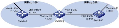
Networking and Configuration Requirements
As shown in Figure 1-3, two RIPng processes are running on Switch B, which communicates with Switch A through RIPng 100 and with Switch C through RIPng 200.
Configure route redistribution on Switch B, letting the two RIPng processes redistribute routes from each other. Set the default cost of redistributed routes from RIPng 200 to 3.
Applicable Product Matrix
|
Product series |
Software version |
Hardware version |
|
S3610 Series Ethernet Switches |
Release 5301 Release 5303 |
All versions |
|
S5510 Series Ethernet Switches |
Release 5301 Release 5303 |
All versions |
|
S7500E Series Ethernet Switches |
Release 6100 Release 6300 |
All versions |
Configuration Procedure
1) Configure IPv6 addresses for the interfaces (omitted).
# Enable RIPng 100 on Switch A.
<SwitchA> system-view
[SwitchA] ripng 100
[SwitchA-ripng-100] quit
[SwitchA] interface vlan-interface 100
[SwitchA-Vlan-interface100] ripng 100 enable
[SwitchA-Vlan-interface100] quit
[SwitchA] interface vlan-interface 200
[SwitchA-Vlan-interface200] ripng 100 enable
# Enable RIP 100 and RIP 200 on Switch B.
<SwitchB> system-view
[SwitchB] ripng 100
[SwitchB-ripng-100] quit
[SwitchB] interface vlan-interface 100
[SwitchB-Vlan-interface100] ripng 100 enable
[SwitchB-Vlan-interface100] quit
[SwitchB] ripng 200
[SwitchB-ripng-200] quit
[SwitchB] interface vlan-interface 300
[SwitchA-Vlan-interface300] ripng 200 enable
# Enable RIPng 200 on Switch C.
<SwitchC> system-view
[SwitchC] ripng 200
[SwitchC] interface vlan-interface 300
[SwitchC-Vlan-interface300] ripng 200 enable
[SwitchC-Vlan-interface300] quit
[SwitchC] interface vlan-interface 400
[SwitchC-Vlan-interface400] ripng 200 enable
[SwitchC-Vlan-interface400] quit
# # Display the IPv6 routing table of Switch A.
[SwitchA] display ipv6 routing-table
Routing Table :
Destinations : 6 Routes : 6
Destination: ::1/128 Protocol : Direct
NextHop : ::1 Preference: 0
Interface : InLoop0 Cost : 0
Destination: 1::/64 Protocol : Direct
NextHop : 1::1 Preference: 0
Interface : Vlan100 Cost : 0
Destination: 1::1/128 Protocol : Direct
NextHop : ::1 Preference: 0
Interface : InLoop0 Cost : 0
Destination: 2::/64 Protocol : Direct
NextHop : 2::1 Preference: 0
Interface : Vlan200 Cost : 0
Destination: 2::1/128 Protocol : Direct
NextHop : ::1 Preference: 0
Interface : InLoop0 Cost : 0
Destination: FE80::/10 Protocol : Direct
NextHop : :: Preference: 0
Interface : NULL0 Cost : 0
2) Configure RIPng route redistribution.
# Configure route redistribution between the two RIPng processes on Switch B.
[SwitchB] ripng 100
[SwitchB-ripng-100] default cost 3
[SwitchB-ripng-100] import-route ripng 200
[SwitchB-ripng-100] quit
[SwitchB] ripng 200
[SwitchB-ripng-200] import-route ripng 100
[SwitchB-ripng-200] quit
# Display the IPv6 routing table of Switch A.
[SwitchA] display ipv6 routing-table
Routing Table :
Destinations : 7 Routes : 7
Destination: ::1/128 Protocol : Direct
NextHop : ::1 Preference: 0
Interface : InLoop0 Cost : 0
Destination: 1::/64 Protocol : Direct
NextHop : 1::1 Preference: 0
Interface : Vlan100 Cost : 0
Destination: 1::1/128 Protocol : Direct
NextHop : ::1 Preference: 0
Interface : InLoop0 Cost : 0
Destination: 2::/64 Protocol : Direct
NextHop : 2::1 Preference: 0
Interface : Vlan200 Cost : 0
Destination: 2::1/128 Protocol : Direct
NextHop : ::1 Preference: 0
Interface : InLoop0 Cost : 0
Destination: 4::/64 Protocol : RIPng
NextHop : FE80::200:BFF:FE01:1C02 Preference: 100
Interface : Vlan100 Cost : 4
Destination: FE80::/10 Protocol : Direct
NextHop : :: Preference: 0
Interface : NULL0 Cost : 0
Complete Configuration
l Configure Switch A.
#
ipv6
#
vlan 100
#
vlan 200
#
interface Vlan-interface100
ipv6 address 1::1/64
ripng 100 enable
#
interface Vlan-interface200
ipv6 address 2::1/64
ripng 100 enable
#
ripng 200
#
l Configure Switch B.
#
ipv6
#
vlan 100
#
vlan 300
#
interface Vlan-interface100
ipv6 address 1::2/64
ripng 100 enable
#
interface Vlan-interface300
ipv6 address 3::1/64
ripng 200 enable
#
ripng 100
default cost 3
import-route ripng 200
#
ripng 200
import-route ripng 100
#
l Configure Switch C.
#
ipv6
#
vlan 300
#
vlan 400
#
interface Vlan-interface300
ipv6 address 3::2/64
ripng 200 enable
#
interface Vlan-interface400
ipv6 address 4::1/64
ripng 200 enable
#
ripng 200
#
Configuration Guidelines
l The S5500-EI series Ethernet switches of Release 2102 support only RIPng single process.
l The S5500-SI series Ethernet switches of Release 1207 or Release 1301 support only RIPng single process.
Configuring IPv6 RIPng over IPv4 Tunnel
Network Diagram
Figure 1-4 Network diagram for IPv6 RIPng over IPv4 tunnel configuration
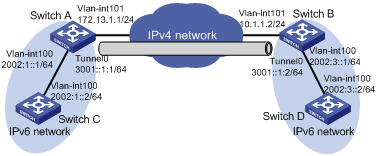
Networking and Configuration Requirements
As shown in Figure 1-4, two IPv6 networks are connected to the IPv4 network respectively through Switch A and Switch B, which are reachable to each other. It is required to configure an IPv6 manual tunnel between Switch A and Switch B so that the two IPv6 networks can communicate with each other through RIPng.
Applicable Product Matrix
|
Product series |
Software version |
Hardware version |
|
S3610 Series Ethernet Switches |
Release 5301 Release 5303 |
All versions |
|
S5510 Series Ethernet Switches |
Release 5301 Release 5303 |
All versions |
|
S5500-EI Series Ethernet Switches |
Release 2102 |
All versions |
|
S7500E Series Ethernet Switches |
Release 6100 Release 6300 |
All versions |
Configuration Procedure
1) Configure IPv6 and IPv4 addresses for the interfaces (omitted)
2) Configure Switch A.
# Enable IPv6.
<SwitchA> system-view
[SwitchA] ipv6
# Configure an IPv6 manual tunnel.
[SwitchA] interface tunnel 0
[SwitchA-Tunnel0] ipv6 address 3001::1:1 64
[SwitchA-Tunnel0] source vlan-interface 101
[SwitchA-Tunnel0] destination 10.1.1.2
[SwitchA-Tunnel0] tunnel-protocol ipv6-ipv4
[SwitchA-Tunnel0] quit
# Configure RIPng basic functions.
[SwitchA] ripng 1
[SwitchA-ripng-1] quit
[SwitchA] interface vlan-interface 100
[SwitchA-Vlan-interface100] ripng 1 enable
[SwitchA-Vlan-interface100] quit
[SwitchA] interface tunnel 0
[SwitchA-Tunnel0] ripng 1 enable
[SwitchA-Tunnel0] quit
3) Configure Switch B.
# Enable IPv6.
<SwitchB> system-view
[SwitchB] ipv6
# Configure an IPv6 manual tunnel.
[SwitchB] interface tunnel 0
[SwitchB-Tunnel0] ipv6 address 3001::1:2 64
[SwitchB-Tunnel0] source vlan-interface 101
[SwitchB-Tunnel0] destination 172.13.1.1
[SwitchB-Tunnel0] tunnel-protocol ipv6-ipv4
[SwitchB-Tunnel0] quit
# Configure RIPng basic functions.
[SwitchA] ripng 1
[SwitchA-ripng-1] quit
[SwitchA] interface vlan-interface 100
[SwitchA-Vlan-interface100] ripng 1 enable
[SwitchA-Vlan-interface100] quit
[SwitchA] interface tunnel 0
[SwitchA-Tunnel0] ripng 1 enable
[SwitchA-Tunnel0] quit
4) Configure Switch C.
# Enable IPv6.
<SwitchC> system-view
[SwitchC] ipv6
# Configure RIPng basic functions.
[SwitchC] ripng 1
[SwitchC-ripng-1] quit
[SwitchC] interface vlan-interface 100
[SwitchC-Vlan-interface100] ripng 1 enable
[SwitchC-Vlan-interface100] quit
5) Configure Switch D.
# Enable IPv6.
<SwitchD> system-view
[SwitchD] ipv6
# Configure RIPng basic functions.
[SwitchD] ripng 1
[SwitchD-ripng-1] quit
[SwitchD] interface vlan-interface 100
[SwitchD-Vlan-interface100] ripng 1 enable
[SwitchD-Vlan-interface100] quit
Use the display ipv6 routing-table command on Switch C and Switch D respectively. You can see that Switch C has learned the network 2002:3::/64 and Switch D has learned the network 2002:1::/64.
Complete Configuration
l Configure Switch A.
#
ipv6
#
vlan 100 to 101
#
interface Vlan-interface100
ipv6 address 2002:1::1/64
ripng 1 enable
#
interface Vlan-interface101
ip address 172.13.1.1 255.255.255.0
#
interface Tunnel0
ipv6 address 3001::1:1/64
ripng 1 enable
tunnel-protocol ipv6-ipv4
source Vlan-interface101
destination 10.1.1.2
#
ripng 1
#
l Configure Switch B.
#
ipv6
#
vlan 100
#
vlan 101
#
interface Vlan-interface100
ipv6 address 2002:3::1/64
ripng 1 enable
#
interface Vlan-interface101
ip address 10.1.1.2 255.255.255.0
#
interface Tunnel0
ipv6 address 3001::1:2/64
ripng 1 enable
tunnel-protocol ipv6-ipv4
source Vlan-interface101
destination 172.13.1.1
#
ripng 1
#
l Configure Switch C.
#
ipv6
#
vlan 100
#
interface Vlan-interface100
ipv6 address 2002:1::2/64
ripng 1 enable
#
ripng 1
#
l Configure Switch D.
#
ipv6
#
vlan 100
#
interface Vlan-interface100
ipv6 address 2002:3::2/64
ripng 1 enable
#
ripng 1
#
Configuration Guidelines
l If the addresses of the tunnel interfaces at the two ends of a tunnel are not in the same network segment, a forwarding route through the tunnel to the peer must be configured so that the encapsulated packets can be forwarded normally. You can configure static or dynamic routing.
l To configure dynamic routing, you must enable the dynamic routing protocol on the tunnel interfaces at both ends of the tunnel.
l For distributed switches, such as the S7500E series, the tunnel interface number is in the A/B/C format, where A, B, and C represent the slot number of a card, the slot number of a sub-card, and the tunnel interface number respectively.
l When you create a tunnel interface on a distributed switch, such as an S7500E switch, the slot number of the tunnel interface should be that of the source interface, namely, the interface sending packets. In this way, the forwarding efficiency can be improved.
Configuring an OSPFv3 Area
Open Shortest Path First version 3 supports IPv6 and complies with RFC2740 (OSPF for IPv6).
OSPFv3 and OSPFv2 have the following in common:
l 32-bit router ID and area ID
l Packets: Hello, DD (Data Description), LSR (Link State Request), LSU (Link State Update), LSAck (Link State Acknowledgment)
l Mechanisms for finding neighbors and establishing adjacencies
l Mechanisms for LSA flooding and aging
Differences between OSPFv3 and OSPFv2 are as follows:
l OSPFv3 now runs on a per-link basis, instead of on a per-IP-subnet basis.
l OSPFv3 supports multiple instances per link.
l OSPFv3 identifies neighbors by Router ID, while OSPFv2 by IP address.
Network Diagram
Figure 1-5 Network diagram for OSPFv3 area configuration
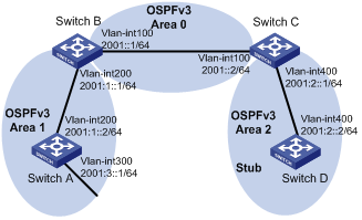
Networking and Configuration Requirements
l In the figure above, all switches run OSPFv3. The AS is split into three areas, in which, Switch B and Switch C act as ABRs to forward routing information between areas.
l It is required to configure Area 2 as a stub area, reducing LSAs into the area without affecting route reachability.
Applicable Product Matrix
|
Product series |
Software version |
Hardware version |
|
S3610 Series Ethernet Switches |
Release 5301 Release 5303 |
All versions |
|
S5510 Series Ethernet Switches |
Release 5301 Release 5303 |
All versions |
|
S5500-EI Series Ethernet Switches |
Release 2102 |
All versions |
|
S7500E Series Ethernet Switches |
Release 6100 Release 6300 |
All versions |
Configuration Procedure
1) Configure IPv6 addresses for interfaces (omitted)
2) Configure OSPFv3 basic functions
# Configure Switch A.
<SwitchA> system-view
[SwitchA] ipv6
[SwitchA] ospfv3
[SwitchA-ospfv3-1] router-id 1.1.1.1
[SwitchA-ospfv3-1] quit
[SwitchA] interface vlan-interface 300
[SwitchA-Vlan-interface300] ospfv3 1 area 1
[SwitchA-Vlan-interface300] quit
[SwitchA] interface vlan-interface 200
[SwitchA-Vlan-interface200] ospfv3 1 area 1
[SwitchA-Vlan-interface200] quit
# Configure Switch B.
<SwitchB> system-view
[SwitchB] ipv6
[SwitchB] ospfv3
[SwitchB-ospf-1] router-id 2.2.2.2
[SwitchB-ospf-1] quit
[SwitchB] interface vlan-interface 100
[SwitchB-Vlan-interface100] ospfv3 1 area 0
[SwitchB-Vlan-interface100] quit
[SwitchB] interface vlan-interface 200
[SwitchB-Vlan-interface200] ospfv3 1 area 1
[SwitchB-Vlan-interface200] quit
# Configure Switch C.
<SwitchC> system-view
[SwitchC] ipv6
[SwitchC] ospfv3
[SwitchC-ospfv3-1] router-id 3.3.3.3
[SwitchC-ospfv3-1] quit
[SwitchC] interface vlan-interface 100
[SwitchC-Vlan-interface100] ospfv3 1 area 0
[SwitchC-Vlan-interface100] quit
[SwitchC] interface vlan-interface 400
[SwitchC-Vlan-interface400] ospfv3 1 area 2
[SwitchC-Vlan-interface400] quit
# Configure Switch D.
<SwitchD> system-view
[SwitchD] ipv6
[SwitchD] ospfv3
[SwitchD-ospfv3-1] router-id 4.4.4.4
[SwitchD-ospfv3-1] quit
[SwitchD] interface vlan-interface 400
[SwitchD-Vlan-interface400] ospfv3 1 area 2
[SwitchD-Vlan-interface400] quit
# Display OSPFv3 neighbor information on Switch B.
[SwitchB] display ospfv3 peer
OSPFv3 Area ID 0.0.0.0 (Process 1)
----------------------------------------------------------------------
Neighbor ID Pri State Dead Time Interface Instance ID
3.3.3.3 1 Full/DR 00:00:39 Vlan100 0
OSPFv3 Area ID 0.0.0.1 (Process 1)
----------------------------------------------------------------------
Neighbor ID Pri State Dead Time Interface Instance ID
1.1.1.1 1 Full/Backup 00:00:38 Vlan200 0
# Display OSPFv3 neighbor information on Switch C.
[SwitchC] display ospfv3 peer
OSPFv3 Area ID 0.0.0.0 (Process 1)
----------------------------------------------------------------------
Neighbor ID Pri State Dead Time Interface Instance ID
2.2.2.2 1 Full/Backup 00:00:39 Vlan100 0
OSPFv3 Area ID 0.0.0.2 (Process 1)
----------------------------------------------------------------------
Neighbor ID Pri State Dead Time Interface Instance ID
4.4.4.4 1 Full/DR 00:00:38 Vlan400 0
# Display OSPFv3 routing table information on Switch D.
[SwitchD] display ospfv3 routing
E1 - Type 1 external route, IA - Inter area route, I - Intra area route
E2 - Type 2 external route, * - Seleted route
OSPFv3 Router with ID (4.4.4.4) (Process 1)
----------------------------------------------------------------------
*Destination: 2001::/64
Type : IA Cost : 2
NextHop : FE80::F40D:0:93D0:1 Interface: Vlan400
*Destination: 2001:1::/64
Type : IA Cost : 3
NextHop : FE80::F40D:0:93D0:1 Interface: Vlan400
*Destination: 2001:2::/64
Type : I Cost : 1
NextHop : directly-connected Interface: Vlan400
*Destination: 2001:3::/64
Type : IA Cost : 4
NextHop : FE80::F40D:0:93D0:1 Interface: Vlan400
3) Configure Area 2 as a stub area
# ConfigureSwitch D.
[SwitchD] ospfv3
[SwitchD-ospfv3-1] area 2
[SwitchD-ospfv3-1-area-0.0.0.2] stub
# Configure Switch C, and specify the cost of the default route sent to the stub area as 10.
[SwitchC] ospfv3
[SwitchC-ospfv3-1] area 2
[SwitchC-ospfv3-1-area-0.0.0.2] stub
[SwitchC-ospfv3-1-area-0.0.0.2] default-cost 10
# Display OSPFv3 routing table information on Switch D. You can find a default route is added, whose cost is the cost of the directly connected route plus the configured cost.
[SwitchD] display ospfv3 routing
E1 - Type 1 external route, IA - Inter area route, I - Intra area route
E2 - Type 2 external route, * - Seleted route
OSPFv3 Router with ID (4.4.4.4) (Process 1)
----------------------------------------------------------------------
*Destination: ::/0
Type : IA Cost : 11
NextHop : FE80::F40D:0:93D0:1 Interface: Vlan400
*Destination: 2001::/64
Type : IA Cost : 2
NextHop : FE80::F40D:0:93D0:1 Interface: Vlan400
*Destination: 2001:1::/64
Type : IA Cost : 3
NextHop : FE80::F40D:0:93D0:1 Interface: Vlan400
*Destination: 2001:2::/64
Type : I Cost : 1
NextHop : directly-connected Interface: Vlan400
*Destination: 2001:3::/64
Type : IA Cost : 4
NextHop : FE80::F40D:0:93D0:1 Interface: Vlan400
4) Configure Area 2 as a totally stub area to reduce the stub area routing table size.
# Configure Area 2 as a totally stub area on Router C.
[SwitchC-ospfv3-1-area-0.0.0.2] stub no-summary
# Display OSPFv3 routing table information on Switch D. You can find route entries are reduced. All non direct routes are removed except the default route.
[SwitchD] display ospfv3 routing
E1 - Type 1 external route, IA - Inter area route, I - Intra area route
E2 - Type 2 external route, * - Seleted route
OSPFv3 Router with ID (4.4.4.4) (Process 1)
----------------------------------------------------------------------
*Destination: ::/0
Type : IA Cost : 11
NextHop : FE80::F40D:0:93D0:1 Interface: Vlan400
*Destination: 2001:2::/64
Type : I Cost : 1
NextHop : directly-connected Interface: Vlan400
Complete Configuration
l Configure Switch A.
#
ipv6
#
vlan 200
#
vlan 300
#
interface Vlan-interface200
ipv6 address 2001:1::2/64
ospfv3 1 area 0.0.0.1
#
interface Vlan-interface300
ipv6 address 2001:3::1/64
ospfv3 1 area 0.0.0.1
#
ospfv3 1
router-id 1.1.1.1
#
l Configure Switch B.
#
ipv6
#
vlan 100
#
vlan 200
#
interface Vlan-interface100
ipv6 address 2001::1/64
ospfv3 1 area 0.0.0.0
#
interface Vlan-interface200
ipv6 address 2001:1::1/64
ospfv3 1 area 0.0.0.1
#
ospfv3 1
router-id 2.2.2.2
#
l Configure Switch C.
#
ipv6
#
vlan 100
#
vlan 400
#
interface Vlan-interface100
ipv6 address 2001::2/64
ospfv3 1 area 0.0.0.0
#
interface Vlan-interface400
ipv6 address 2001:2::1/64
ospfv3 1 area 0.0.0.2
#
ospfv3 1
router-id 3.3.3.3
area 0.0.0.2
stub no-summary
default-cost 10
#
l Configure Switch D.
#
ipv6
#
vlan 400
#
interface Vlan-interface400
ipv6 address 2001:2::2/64
ospfv3 1 area 0.0.0.2
#
ospfv3 1
router-id 4.4.4.4
area 0.0.0.2
stub
#
Configuration Guidelines
l You cannot delete an OSPFv3 area directly. Only when you remove all configurations in area view and all interfaces attached to the area become down can the area be removed automatically.
l All routers attached to a stub area must be configured with the stub command. The keyword no-summary is only available on the ABR.
l If you use the stub command with the keyword no-summary on an ABR, the ABR distributes a default summary LSA into the area rather than generating an AS-external-LSA or Inter-Area-Prefix-LSA. The stub area of this kind is also known as totally stub area.
l To enable an OSPFv3 process on a router, you need to enable the OSPFv3 process globally, assign the OSPFv3 process a router ID, and enable the OSPFv3 process on related interfaces.
l A router ID uniquely identifies a router within an AS. Therefore, you need to specify a unique router ID for each OSPFv3 router within the AS to ensure normal operation. Note that if a router runs multiple OSPFv3 processes, you need to specify a unique router ID for each process.
Configuring OSPFv3 Route Redistribution
Network Diagram
Figure 1-6 Network diagram for OSPFv3 route redistribution configuration
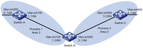
Networking and Configuration Requirements
l Switch A, Switch B, and Switch C are in Area 2.
l OSPFv3 process 1 and OSPFv3 process 2 are enabled on Switch B. Switch B communicates with Switch A and Switch C through OSPFv3 process 1 and OSPFv3 process 2 respectively.
l Configure OSPFv3 process 2 to redistribute direct routes and the routes from OSPFv3 process 1 on Switch B and set the default metric for redistributed routes to 3. Thus, Switch C can learn the routes destined for 1::0/64 and 2::0/64, while Switch A cannot learn the routes destined for 3::0/64 or 4::0/64.
Applicable Product Matrix
|
Product series |
Software version |
Hardware version |
|
S3610 Series Ethernet Switches |
Release 5301 Release 5303 |
All versions |
|
S5510 Series Ethernet Switches |
Release 5301 Release 5303 |
All versions |
|
S7500E Series Ethernet Switches |
Release 6100 Release 6300 |
All versions |
Configuration Procedure
1) Configure IPv6 addresses for interfaces (omitted)
# # Enable OSPFv3 process 1 on Switch A.
<SwitchA> system-view
[SwitchA] ipv6
[SwitchA] ospfv3 1
[SwitchA-ospfv3-1] router-id 1.1.1.1
[SwitchA-ospfv3-1] quit
[SwitchA] interface Vlan-interface 100
[SwitchA-Vlan-interface100] ospfv3 1 area 2
[SwitchA-Vlan-interface100] quit
[SwitchA] interface Vlan-interface 200
[SwitchA-Vlan-interface200] ospfv3 1 area 2
[SwitchA-Vlan-interface200] quit
# Enable OSPFv3 process 1 and OSPFv3 process 2 on Switch B.
<SwitchB> system-view
[SwitchB] ipv6
[SwitchB] ospfv3 1
[SwitchB-ospfv3-1] router-id 2.2.2.2
[SwitchB-ospfv3-1] quit
[SwitchB] interface Vlan-interface 100
[SwitchB-Vlan-interface100] ospfv3 1 area 2
[SwitchB-Vlan-interface100] quit
[SwitchB] ospfv3 2
[SwitchB-ospfv3-2] router-id 3.3.3.3
[SwitchB-ospfv3-2] quit
[SwitchB] interface Vlan-interface 300
[SwitchB-Vlan-interface300] ospfv3 2 area 2
[SwitchB-Vlan-interface300] quit
# Enable OSPFv3 process 2 on Switch C.
<SwitchC> system-view
[SwitchC] ipv6
[SwitchC] ospfv3 2
[SwitchC-ospfv3-2] router-id 4.4.4.4
[SwitchC-ospfv3-2] quit
[SwitchC] interface Vlan-interface 300
[SwitchC-Vlan-interface300] ospfv3 2 area 2
[SwitchC-Vlan-interface300] quit
[SwitchC] interface Vlan-interface 400
[SwitchC-Vlan-interface400] ospfv3 2 area 2
[SwitchC-Vlan-interface400] quit
# Display the routing table of Switch C.
[SwitchB] display ipv6 routing-table
Routing Table :
Destinations : 6 Routes : 6
Destination: ::1/128 Protocol : Direct
NextHop : ::1 Preference: 0
Interface : InLoop0 Cost : 0
Destination: 3::/64 Protocol : Direct
NextHop : 3::2 Preference: 0
Interface : Vlan300 Cost : 0
Destination: 3::2/128 Protocol : Direct
NextHop : ::1 Preference: 0
Interface : InLoop0 Cost : 0
Destination: 4::/64 Protocol : Direct
NextHop : 4::1 Preference: 0
Interface : Vlan400 Cost : 0
Destination: 4::1/128 Protocol : Direct
NextHop : ::1 Preference: 0
Interface : InLoop0 Cost : 0
Destination: FE80::/10 Protocol : Direct
NextHop : :: Preference: 0
Interface : NULL0 Cost : 0
2) Configure OSPFv3 route redistribution
# Configure OSPFv3 process 2 to redistribute direct routes and the routes from OSPFv3 process 1 on Switch B.
[SwitchB] ospfv3 2
[SwitchB-ospfv3-2] default cost 3
[SwitchB-ospfv3-2] import-route ospfv3 1
[SwitchB-ospfv3-2] import-route direct
[SwitchB-ospfv3-2] quit
# Display the routing table of Switch C.
[SwitchC] display ipv6 routing-table
Routing Table :
Destinations : 8 Routes : 8
Destination: ::1/128 Protocol : Direct
NextHop : ::1 Preference: 0
Interface : InLoop0 Cost : 0
Destination: 1::/64 Protocol : OSPFv3
NextHop : FE80::200:CFF:FE01:1C03 Preference: 150
Interface : Vlan300 Cost : 3
Destination: 2::/64 Protocol : OSPFv3
NextHop : FE80::200:CFF:FE01:1C03 Preference: 150
Interface : Vlan300 Cost : 3
Destination: 3::/64 Protocol : Direct
NextHop : 3::2 Preference: 0
Interface : Vlan300 Cost : 0
Destination: 3::2/128 Protocol : Direct
NextHop : ::1 Preference: 0
Interface : InLoop0 Cost : 0
Destination: 4::/64 Protocol : Direct
NextHop : 4::1 Preference: 0
Interface : Vlan400 Cost : 0
Destination: 4::1/128 Protocol : Direct
NextHop : ::1 Preference: 0
Interface : InLoop0 Cost : 0
Destination: FE80::/10 Protocol : Direct
NextHop : :: Preference: 0
Interface : NULL0 Cost : 0
Complete Configuration
l Configure Switch A.
#
ipv6
#
vlan 100
#
vlan 200
#
interface Vlan-interface100
ipv6 address 1::1/64
ospfv3 1 area 0.0.0.2
#
interface Vlan-interface200
ipv6 address 2::1/64
ospfv3 1 area 0.0.0.2
#
ospfv3 1
router-id 1.1.1.1
#
l Configure Switch B.
#
ipv6
#
vlan 100
#
vlan 300
#
interface Vlan-interface100
ipv6 address 1::2/64
ospfv3 1 area 0.0.0.2
#
interface Vlan-interface300
ipv6 address 3::1/64
ospfv3 2 area 0.0.0.2
#
ospfv3 1
router-id 2.2.2.2
#
ospfv3 2
router-id 3.3.3.3
default cost 3
import-route direct
import-route ospfv3 1
#
l Configure Switch C.
#
ipv6
#
vlan 300
#
vlan 400
#
interface Vlan-interface300
ipv6 address 3::2/64
ospfv3 2 area 0.0.0.2
#
interface Vlan-interface400
ipv6 address 4::1/64
ospfv3 2 area 0.0.0.2
#
ospfv3 2
router-id 4.4.4.4
#
Configuration Guidelines
l To enable an OSPFv3 process on a router, you need to enable the OSPFv3 process globally, assign the OSPFv3 process a router ID, and enable the OSPFv3 process on related interfaces.
l A router ID uniquely identifies a router within an AS. Therefore, you need to specify a unique router ID for each OSPFv3 router within the AS to ensure normal operation. Note that if a router runs multiple OSPFv3 processes, you need to specify a unique router ID for each process.
l The S5500-EI series Ethernet switches of Release 2102 support only OSPFv3 single process.
Configure OSPFv3 DR Election
Network Diagram
Figure 1-7 Network diagram for OSPFv3 DR selection configuration
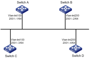
Networking and Configuration Requirements
l The priority of Switch A is 100, the highest priority on the network, so it will be the DR.
l The priority of Switch C is 2, the second highest priority on the network, so it will be the BDR.
l The priority of Switch B is 0, so it cannot become the DR.
l Switch D has the default priority 1.
Applicable Product Matrix
|
Product series |
Software version |
Hardware version |
|
S3610 Series Ethernet Switches |
Release 5301 Release 5303 |
All versions |
|
S5510 Series Ethernet Switches |
Release 5301 Release 5303 |
All versions |
|
S5500-EI Series Ethernet Switches |
Release 2102 |
All versions |
|
S7500E Series Ethernet Switches |
Release 6100 Release 6300 |
All versions |
Configuration Procedure
1) Configure IPv6 addresses for interfaces (omitted)
2) Configure OSPFv3 basic functions
# Configure Switch A.
<SwitchA> system-view
[SwitchA] ipv6
[SwitchA] ospfv3
[SwitchA-ospfv3-1] router-id 1.1.1.1
[SwitchA-ospfv3-1] quit
[SwitchA] interface vlan-interface 100
[SwitchA-Vlan-interface100] ospfv3 1 area 0
[SwitchA-Vlan-interface100] quit
# Configure Switch B.
<SwitchB> system-view
[SwitchB] ipv6
[SwitchB] ospfv3
[SwitchB-ospfv3-1] router-id 2.2.2.2
[SwitchB-ospfv3-1] quit
[SwitchB] interface vlan-interface 200
[SwitchB-Vlan-interface200] ospfv3 1 area 0
[SwitchB-Vlan-interface200] quit
# Configure Switch C.
<SwitchC> system-view
[SwitchC] ipv6
[SwitchC] ospfv3
[SwitchC-ospfv3-1] router-id 3.3.3.3
[SwitchC-ospfv3-1] quit
[SwitchC] interface vlan-interface 100
[SwitchC-Vlan-interface100] ospfv3 1 area 0
[SwitchC-Vlan-interface100] quit
# Configure Switch D.
<SwitchD> system-view
[SwitchD] ipv6
[SwitchD] ospfv3
[SwitchD-ospfv3-1] router-id 4.4.4.4
[SwitchD-ospfv3-1] quit
[SwitchD] interface vlan-interface 200
[SwitchD-Vlan-interface200] ospfv3 1 area 0
[SwitchD-Vlan-interface200] quit
# Display neighbor information on Switch A. You can find the switches have the same default DR priority 1. In this case, the switch with the highest Router ID is elected as the DR. Therefore, Switch D is the DR, and Switch C is the BDR.
[SwitchA] display ospfv3 peer
OSPFv3 Area ID 0.0.0.0 (Process 1)
----------------------------------------------------------------------
Neighbor ID Pri State Dead Time Interface Instance ID
2.2.2.2 1 2-Way/DROther 00:00:36 Vlan200 0
3.3.3.3 1 Full/Backup 00:00:35 Vlan100 0
4.4.4.4 1 Full/DR 00:00:33 Vlan200 0
# Display neighbor information on Switch D. You can find the neighbor states are all Full.
[SwitchD] display ospfv3 peer
OSPFv3 Area ID 0.0.0.0 (Process 1)
----------------------------------------------------------------------
Neighbor ID Pri State Dead Time Interface Instance ID
1.1.1.1 1 Full/DROther 00:00:30 Vlan100 0
2.2.2.2 1 Full/DROther 00:00:37 Vlan200 0
3.3.3.3 1 Full/Backup 00:00:31 Vlan100 0
3) Configure DR priorities for interfaces.
# Configure the DR priority of VLAN-interface 100 as 100 on Switch A
[SwitchA] interface vlan-interface 100
[SwitchA-Vlan-interface100] ospfv3 dr-priority 100
[SwitchA-Vlan-interface100] quit
# Configure the DR priority of VLAN-interface 200 as 0 on Switch B.
[SwitchB] interface vlan-interface 200
[SwitchB-Vlan-interface200] ospfv3 dr-priority 0
[SwitchB-Vlan-interface200] quit
# Configure the DR priority of VLAN-interface 100 of Switch C as 2.
[SwitchC] interface vlan-interface 100
[SwitchC-Vlan-interface100] ospfv3 dr-priority 2
[SwitchC-Vlan-interface100] quit
# Display neighbor information on Switch A. You can find DR priorities have been updated, but the DR and BDR are not changed.
[SwitchA] display ospfv3 peer
OSPFv3 Area ID 0.0.0.0 (Process 1)
----------------------------------------------------------------------
Neighbor ID Pri State Dead Time Interface Instance ID
2.2.2.2 0 2-Way/DROther 00:00:38 Vlan200 0
3.3.3.3 2 Full/Backup 00:00:32 Vlan100 0
4.4.4.4 1 Full/DR 00:00:36 Vlan200 0
# Display neighbor information on Switch D. You can find Switch D is still the DR.
[SwitchD] display ospfv3 peer
OSPFv3 Area ID 0.0.0.0 (Process 1)
----------------------------------------------------------------------
Neighbor ID Pri State Dead Time Interface Instance ID
1.1.1.1 100 Full/DROther 00:00:33 Vlan100 0
2.2.2.2 0 Full/DROther 00:00:36 Vlan200 0
3.3.3.3 2 Full/Backup 00:00:40 Vlan100 0
4) Restart DR/BDR election
# Use the shutdown and undo shutdown commands on interfaces to restart DR/BDR election (omitted).
# Display neighbor information on Switch A. You can find Switch C becomes the BDR.
[SwitchA] display ospfv3 peer
OSPFv3 Area ID 0.0.0.0 (Process 1)
----------------------------------------------------------------------
Neighbor ID Pri State Dead Time Interface Instance ID
2.2.2.2 0 Full/DROther 00:00:31 Vlan200 0
3.3.3.3 2 Full/Backup 00:00:39 Vlan100 0
4.4.4.4 1 Full/DROther 00:00:37 Vlan200 0
# Display neighbor information on Switch D. You can find Switch A becomes the DR.
[SwitchD] display ospfv3 peer
OSPFv3 Area ID 0.0.0.0 (Process 1)
----------------------------------------------------------------------
Neighbor ID Pri State Dead Time Interface Instance ID
1.1.1.1 100 Full/DR 00:00:34 Vlan100 0
2.2.2.2 0 2-Way/DROther 00:00:34 Vlan200 0
3.3.3.3 2 Full/Backup 00:00:32 Vlan100 0
Complete Configuration
l Configure Switch A.
#
ipv6
#
vlan 100
#
interface Vlan-interface100
ipv6 address 2001::1/64
ospfv3 1 area 0.0.0.0
ospfv3 dr-priority 100
#
ospfv3 1
router-id 1.1.1.1
#
l Configure Switch B.
#
ipv6
#
vlan 200
#
interface Vlan-interface200
ipv6 address 2001::2/64
ospfv3 1 area 0.0.0.0
ospfv3 dr-priority 0
#
ospfv3 1
router-id 2.2.2.2
#
l Configure Switch C.
#
ipv6
#
vlan 100
#
#
interface Vlan-interface100
ipv6 address 2001::3/64
ospfv3 1 area 0.0.0.0
ospfv3 dr-priority 2
#
ospfv3 1
router-id 3.3.3.3
#
l Configure Switch D.
#
ipv6
#
vlan 200
#
interface Vlan-interface200
ipv6 address 2001::4/64
ospfv3 1 area 0.0.0.0
#
ospfv3 1
router-id 4.4.4.4
#
Configuration Guidelines
l To enable an OSPFv3 process on a router, you need to enable the OSPFv3 process globally, assign the OSPFv3 process a router ID, and enable the OSPFv3 process on related interfaces.
l A router ID uniquely identifies a router within an AS. Therefore, you need to specify a unique router ID for each OSPFv3 router within the AS to ensure normal operation. Note that if a router runs multiple OSPFv3 processes, you need to specify a unique router ID for each process.
Configuring IPv6 IS-IS
The IS-IS routing protocol (Intermediate System-to-Intermediate System intra-domain routing information exchange protocol) supports multiple network protocols, including IPv6. IS-IS with IPv6 support is called IPv6 IS-IS dynamic routing protocol. The international engineer task force (IETF) defines two type-length-values (TLVs) and a new network layer protocol identifier (NLPID) to enable IPv6 support for IS-IS.
TLV is a variable field in the link state PDU or link state packet (LSP). The two TLVs are:
l IPv6 Reachability: Defines the prefix, metric of routing information to indicate the network reachability, with a type value of 236 (0xEC).
l IPv6 Interface Address: Similar with the “IP Interface Address” TLV of IPv4, it transforms the 32-bit IPv4 address to the 128-bit IPv6 address.
NLPID is an 8-bit field with a value of 142 (0x8E), which indicates the network layer protocol packet. If the IS-IS router supports IPv6, the advertised routing information must be marked with the NLPID.
Network Diagram
Figure 1-8 Network diagram for IPv6 IS-IS configuration
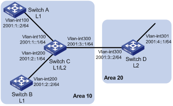
Networking and Configuration Requirements
As shown in figure above, Switch A, Switch B, Switch C and Switch D reside in the same autonomous system, and all are enabled with IPv6.
Switch A and Switch B are Level-1 switches, Switch D is a Level-2 switch, and Switch C is a Level-1-2 switch. Switch A, Switch B, and Switch C are in area 10, while Switch D is in area 20.
Applicable Product Matrix
|
Product series |
Software version |
Hardware version |
|
S3610 Series Ethernet Switches |
Release 5301 Release 5303 |
All versions |
|
S5510 Series Ethernet Switches |
Release 5301 Release 5303 |
All versions |
|
S5500-EI Series Ethernet Switches |
Release 2102 |
All versions |
|
S7500E Series Ethernet Switches |
Release 6100 Release 6300 |
All versions |
Configuration Procedure
1) Configure IPv6 addresses for interfaces (omitted)
2) Configure IPv6 IS-IS
# Configure Switch A.
<SwitchA> system-view
[SwitchA] isis 1
[SwitchA-isis-1] is-level level-1
[SwitchA-isis-1] network-entity 10.0000.0000.0001.00
[SwitchA-isis-1] ipv6 enable
[SwitchA-isis-1] quit
[SwitchA] interface vlan-interface 100
[SwitchA-Vlan-interface100] isis ipv6 enable 1
[SwitchA-Vlan-interface100] quit
# Configure Switch B.
<SwitchB> system-view
[SwitchB] isis 1
[SwitchB-isis-1] is-level level-1
[SwitchB-isis-1] network-entity 10.0000.0000.0002.00
[SwitchB-isis-1] ipv6 enable
[SwitchB-isis-1] quit
[SwitchB] interface vlan-interface 200
[SwitchB-Vlan-interface200] isis ipv6 enable 1
[SwitchB-Vlan-interface200] quit
# Configure Switch C.
<SwitchC> system-view
[SwitchC] isis 1
[SwitchC-isis-1] network-entity 10.0000.0000.0003.00
[SwitchC-isis-1] ipv6 enable
[SwitchC-isis-1] quit
[SwitchC] interface vlan-interface 100
[SwitchC-Vlan-interface100] isis ipv6 enable 1
[SwitchC-Vlan-interface100] quit
[SwitchC] interface vlan-interface 200
[SwitchC-Vlan-interface200] isis ipv6 enable 1
[SwitchC-Vlan-interface200] quit
[SwitchC] interface vlan-interface 300
[SwitchC-Vlan-interface300] isis ipv6 enable 1
[SwitchC-Vlan-interface300] quit
# Configure Switch D.
<SwitchD> system-view
[SwitchD] isis 1
[SwitchD-isis-1] is-level level-2
[SwitchD-isis-1] network-entity 20.0000.0000.0004.00
[SwitchD-isis-1] ipv6 enable
[SwitchD-isis-1] quit
[SwitchD] interface vlan-interface 300
[SwitchD-Vlan-interface300] isis ipv6 enable 1
[SwitchD-Vlan-interface300] quit
[SwitchD] interface vlan-interface 301
[SwitchD-Vlan-interface301] isis ipv6 enable 1
[SwitchD-Vlan-interface301] quit
Complete Configuration
l Configure Switch A.
#
ipv6
#
vlan 100
#
isis 1
is-level level-1
network-entity 10.0000.0000.0001.00
#
ipv6 enable
#
#
interface Vlan-interface100
ipv6 address 2001:1::2/64
isis ipv6 enable 1
#
l Configure Switch B.
#
ipv6
#
vlan 200
#
isis 1
is-level level-1
network-entity 10.0000.0000.0002.00
#
ipv6 enable
#
interface Vlan-interface200
ipv6 address 2001:2::2/64
isis ipv6 enable 1
#
l Configure Switch C.
#
ipv6
#
vlan 100
#
vlan 200
#
vlan 300
#
isis 1
network-entity 10.0000.0000.0003.00
#
ipv6 enable
#
#
interface Vlan-interface100
ipv6 address 2001:1::1/64
isis ipv6 enable 1
#
interface Vlan-interface200
ipv6 address 2001:2::1/64
isis ipv6 enable 1
#
interface Vlan-interface300
ipv6 address 2001:3::1/64
isis ipv6 enable 1
#
l Configure Switch D.
#
ipv6
#
vlan 300 to 301
#
isis 1
is-level level-2
network-entity 20.0000.0000.0004.00
#
ipv6 enable
#
interface Vlan-interface300
ipv6 address 2001:3::2/64
isis ipv6 enable 1
#
interface Vlan-interface301
ipv6 address 2001:4::1/64
isis ipv6 enable 1
#
Configuration Guidelines
None
Configuring IPv6 BGP
BGP-4 manages only IPv4 routing information, thus other network layer protocols such as IPv6 are not supported.
To support multiple network layer protocols, IETF extended BGP-4 by introducing IPv6 BGP that is defined in RFC 2858 (multiprotocol extensions for BGP-4).
To implement IPv6 support, IPv6 BGP puts IPv6 network layer information into the attributes of network layer reachable information (NLRI) and NEXT_HOP.
NLRI attribute of IPv6 BGP involves:
l MP_REACH_NLRI: Multiprotocol Reachable NLRI, for advertisement of next hop information of reachable routes.
l MP_UNREACH_NLRI: Multiprotocol Unreachable NLRI, for withdrawal of unreachable routes.
The NEXT_HOP attribute of IPv6 BGP is identified by an IPv6 unicast address or IPv6 local link address.
IPv6 BGP utilizes BGP multiprotocol extensions for application in IPv6 networks. The original messaging and routing mechanisms of BGP are not changed.
Network Diagram
Figure 1-9 Network diagram for IPv6 BGP basic configuration
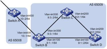
Networking and Configuration Requirements
In the figure above are all IPv6 BGP switches. Between Switch A and Switch B is an EBGP connection. Switch B, Switch C and Switch D are iBGP fully meshed.
Applicable Product Matrix
|
Product series |
Software version |
Hardware version |
|
S3610 Series Ethernet Switches |
Release 5301 Release 5303 |
All versions |
|
S5510 Series Ethernet Switches |
Release 5301 Release 5303 |
All versions |
|
S5500-EI Series Ethernet Switches |
Release 2102 |
All versions |
|
S7500E Series Ethernet Switches |
Release 6100 Release 6300 |
All versions |
Configuration Procedure
1) Configure IPv6 addresses for interfaces (omitted)
2) Configure iBGP connections
# Configure Switch B.
<SwitchB> system-view
[SwitchB] ipv6
[SwitchB] bgp 65009
[SwitchB-bgp] router-id 2.2.2.2
[SwitchB-bgp] ipv6-family
[SwitchB-bgp-af-ipv6] peer 9:1::2 as-number 65009
[SwitchB-bgp-af-ipv6] peer 9:3::2 as-number 65009
[SwitchB-bgp-af-ipv6] quit
[SwitchB-bgp] quit
# Configure Switch C.
<SwitchC> system-view
[SwitchC] ipv6
[SwitchC] bgp 65009
[SwitchC-bgp] router-id 3.3.3.3
[SwitchC-bgp] ipv6-family
[SwitchC-bgp-af-ipv6] peer 9:3::1 as-number 65009
[SwitchC-bgp-af-ipv6] peer 9:2::2 as-number 65009
[SwitchC-bgp-af-ipv6] quit
[SwitchC-bgp] quit
# Configure Switch D.
<SwitchD> system-view
[SwitchD] ipv6
[SwitchD] bgp 65009
[SwitchD-bgp] router-id 4.4.4.4
[SwitchD-bgp] ipv6-family
[SwitchD-bgp-af-ipv6] peer 9:1::1 as-number 65009
[SwitchD-bgp-af-ipv6] peer 9:2::1 as-number 65009
[SwitchD-bgp-af-ipv6] quit
[SwitchD-bgp] quit
3) Configure the eBGP connection
# Configure Switch A.
<SwitchA> system-view
[SwitchA] ipv6
[SwitchA] bgp 65008
[SwitchA-bgp] router-id 1.1.1.1
[SwitchA-bgp] ipv6-family
[SwitchA-bgp-af-ipv6] peer 10::1 as-number 65009
[SwitchA-bgp-af-ipv6] quit
[SwitchA-bgp] quit
# Configure Switch B.
[SwitchB] bgp 65009
[SwitchB-bgp] ipv6-family
[SwitchB-bgp-af-ipv6] peer 10::2 as-number 65008
# Display IPv6 peer information on Switch B.
[SwitchB] display bgp ipv6 peer
BGP local router ID : 2.2.2.2
Local AS number : 65009
Total number of peers : 3 Peers in established state : 3
Peer V AS MsgRcvd MsgSent OutQ PrefRcv Up/Down State
10::2 4 65008 3 3 0 0 00:01:16 Established
9:3::2 4 65009 2 3 0 0 00:00:40 Established
9:1::2 4 65009 2 4 0 0 00:00:19 Established
# Display IPv6 peer information on Switch C.
[SwitchC] display bgp ipv6 peer
BGP local router ID : 3.3.3.3
Local AS number : 65009
Total number of peers : 2 Peers in established state : 2
Peer V AS MsgRcvd MsgSent OutQ PrefRcv Up/Down State
9:3::1 4 65009 4 4 0 0 00:02:18 Established
9:2::2 4 65009 4 5 0 0 00:01:52 Established
Switch A and B established an eBGP connection; Switch B, C and D established iBGP connections with each other.
Complete Configuration
l Configure Switch A.
#
ipv6
#
vlan 400
#
interface Vlan-interface400
ipv6 address 10::2/64
#
bgp 65008
router-id 1.1.1.1
#
ipv6-family
peer 10::1 as-number 65009
#
l Configure Switch B.
#
ipv6
#
vlan 100
#
vlan 300
#
vlan 400
#
interface Vlan-interface100
ipv6 address 9:1::1/64
#
interface Vlan-interface300
ipv6 address 9:3::1/64
#
interface Vlan-interface400
ipv6 address 10::1/64
#
bgp 65009
router-id 2.2.2.2
#
ipv6-family
peer 10::2 as-number 65008
peer 9:1::2 as-number 65009
peer 9:3::2 as-number 65009
#
l Configure Switch C.
#
ipv6
#
vlan 200
#
vlan 300
#
interface Vlan-interface200
ipv6 address 9:2::1/64
#
interface Vlan-interface300
ipv6 address 9:3::2/64
#
bgp 65009
router-id 3.3.3.3
#
ipv6-family
peer 9:3::1 as-number 65009
peer 9:2::2 as-number 65009
#
l Configure Switch D.
#
ipv6
#
vlan 100
#
vlan 200
#
interface Vlan-interface100
ipv6 address 9:1::2/64
#
interface Vlan-interface200
ipv6 address 9:2::2/64
#
bgp 65009
router-id 4.4.4.4
#
ipv6-family
peer 9:1::1 as-number 65009
peer 9:2::1 as-number 65009
#
Configuration Guidelines
l To improve stability and reliability, you can specify a loopback interface as the source interface for establishing TCP connections to a BGP peer. By doing so, a connection failure upon redundancy availability will not affect TCP connection establishment.
l To establish multiple BGP connections to a BGP router, you need to specify on the local router the respective source interfaces for establishing TCP connections to the peers on the peering BGP router; otherwise, the local BGP router may fail to establish TCP connections to the peers when using the outbound interfaces of the best routes as the source interfaces.
l In general, direct links should be available between eBGP peers. If not, you can use the peer ebgp-max-hop command to establish a multi-hop TCP connection in between. However, you need not use this command for direct EBGP connection with loopback interfaces.
Configuring IPv6 BGP Route Reflector
Network Diagram
Figure 1-10 Network diagram for IPv6 BGP route reflector configuration
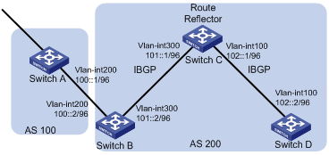
Networking and Configuration Requirements
Switch B receives an EBGP update and sends it to Switch C, which is configured as a route reflector with two clients: Switch B and Switch D.
Switch B and Switch D need not establish an IBGP connection because Switch C reflects updates between them.
Applicable Product Matrix
|
Product series |
Software version |
Hardware version |
|
S3610 Series Ethernet Switches |
Release 5301 Release 5303 |
All versions |
|
S5510 Series Ethernet Switches |
Release 5301 Release 5303 |
All versions |
|
S5500-EI Series Ethernet Switches |
Release 2102 |
All versions |
|
S7500E Series Ethernet Switches |
Release 6100 Release 6300 |
All versions |
Configuration Procedure
1) Configure IPv6 addresses for VLAN interfaces (omitted)
2) Configure IPv6 BGP basic functions
# Configure Switch A.
<SwitchA> system-view
[SwitchA] ipv6
[SwitchA] bgp 100
[SwitchA-bgp] router-id 1.1.1.1
[SwitchA-bgp] ipv6-family
[SwitchA-bgp-af-ipv6] peer 100::2 as-number 200
[SwitchA-bgp-af-ipv6] network 1:: 64
#Configure Switch B.
<SwitchB> system-view
[SwitchB] ipv6
[SwitchB] bgp 200
[SwitchB-bgp] router-id 2.2.2.2
[SwitchB-bgp] ipv6-family
[SwitchB-bgp-af-ipv6] peer 100::1 as-number 100
[SwitchB-bgp-af-ipv6] peer 101::1 as-number 200
[SwitchB-bgp-af-ipv6] peer 101::1 next-hop-local
# Configure Switch C.
<SwitchC> system-view
[SwitchC] ipv6
[SwitchC] bgp 200
[SwitchC-bgp] router-id 3.3.3.3
[SwitchC-bgp] ipv6-family
[SwitchC-bgp-af-ipv6] peer 101::2 as-number 200
[SwitchC-bgp-af-ipv6] peer 102::2 as-number 200
# Configure Switch D.
<SwitchD> system-view
[SwitchD] ipv6
[SwitchD] bgp 200
[SwitchD-bgp] router-id 4.4.4.4
[SwitchD-bgp] ipv6-family
[SwitchD-bgp-af-ipv6] peer 102::1 as-number 200
3) Configure route reflector
# Configure Switch C as a route reflector, Switch B and Switch D as its clients.
[SwitchC-bgp-af-ipv6] peer 101::2 reflect-client
[SwitchC-bgp-af-ipv6] peer 102::2 reflect-client
Use the display bgp ipv6 routing-table command on Switch B and Switch D respectively. You can find both of them have learned the network 1::/64.
Complete Configuration
l Configure Switch A.
#
ipv6
#
vlan 200
#
interface Vlan-interface200
ipv6 address 100::1/96
#
bgp 100
router-id 1.1.1.1
#
ipv6-family
network 1:: 64
peer 100::2 as-number 200
#
l Configure Switch B.
#
ipv6
#
vlan 200
#
vlan 300
#
interface Vlan-interface200
ipv6 address 100::2/96
#
interface Vlan-interface300
ipv6 address 101::2/96
#
bgp 200
router-id 2.2.2.2
#
ipv6-family
peer 100::1 as-number 100
peer 101::1 as-number 200
peer 101::1 next-hop-local
#
l Configure Switch C.
#
ipv6
#
vlan 100
#
vlan 300
#
interface Vlan-interface100
ipv6 address 102::1/96
#
interface Vlan-interface300
ipv6 address 101::1/96
#
bgp 200
router-id 3.3.3.3
#
ipv6-family
peer 101::2 as-number 200
peer 102::2 as-number 200
peer 101::2 reflect-client
peer 102::2 reflect-client
#
l Configure Switch D.
#
ipv6
#
vlan 100
#
interface Vlan-interface100
ipv6 address 102::2/96
#
bgp 200
router-id 4.4.4.4
#
ipv6-family
peer 102::1 as-number 200
#
Configuration Guidelines
l In general, since the route reflector forwards routing information between clients, it is not required to make clients of a route reflector fully meshed. If clients are fully meshed, it is recommended to disable route reflection between clients to reduce routing costs.
l If a cluster has multiple route reflectors, you need to specify the same cluster ID for these route reflectors to avoid routing loops.
Configuring Route Policy Application in IPv6 Route Redistribution
A routing policy is used on the router for route inspection, filtering, attributes modifying when routes are received, advertised, or redistributed.
When distributing or receiving routing information, a router can use a routing policy to filter routing information. For example, a router receives or advertises only routing information that matches the criteria of a routing policy; a routing protocol redistributes routes from another protocol only routes matching the criteria of a routing policy and modifies some attributes of these routes to satisfy its needs using the routing policy.
To implement a routing policy, you need to define a set of match criteria according to attributes in routing information, such as destination address, advertising router’s address and so on. The match criteria can be set beforehand and then apply them to a routing policy for route distribution, reception and redistribution.
Network Diagram
Figure 1-11 Network diagram for route policy application in IPv6 route redistribution
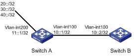
Networking and Configuration Requirements
l Enable RIPng on Switch A and Switch B.
l Configure three static routes on Switch A and apply a routing policy when redistributing static routes, making routes 20::0/32 and 40::0/32 pass, routes in 30::0/32 filtered out.
l Display RIPng routing table information on Switch B to verify the configuration.
Applicable Product Matrix
|
Product series |
Software version |
Hardware version |
|
S3610 Series Ethernet Switches |
Release 5301 Release 5303 |
All versions |
|
S5510 Series Ethernet Switches |
Release 5301 Release 5303 |
All versions |
|
S5500-SI Series Ethernet Switches |
Release 1207 |
All versions, except S5500-20TP-SI |
|
Release 1301 |
S5500-20TP-SI |
|
|
S5500-EI Series Ethernet Switches |
Release 2102 |
All versions |
|
S7500E Series Ethernet Switches |
Release 6100 Release 6300 |
All versions |
Configuration Procedure
1) Configure Switch A
# Configure IPv6 addresses for VLAN-interface 100 and VLAN-interface 200.
<SwitchA> system-view
[SwitchA] ipv6
[SwitchA] interface vlan-interface 100
[SwitchA-Vlan-interface100] ipv6 address 10::1 32
[SwitchA-Vlan-interface100] quit
[SwitchA] interface vlan-interface 200
[SwitchA-Vlan-interface200] ipv6 address 11::1 32
[SwitchA-Vlan-interface200] quit
# Enable RIPng on VLAN-interface 100.
[SwitchA] interface vlan-interface 100
[SwitchA-Vlan-interface100] ripng 1 enable
[SwitchA-Vlan-interface100] quit
# Configure three static routes.
[SwitchA] ipv6 route-static 20:: 32 11::2
[SwitchA] ipv6 route-static 30:: 32 11::2
[SwitchA] ipv6 route-static 40:: 32 11::2
# Configure a routing policy.
[SwitchA] ip ipv6-prefix a index 10 permit 30:: 32
[SwitchA] route-policy static2ripng deny node 0
[SwitchA-route-policy] if-match ipv6 address prefix-list a
[SwitchA-route-policy] quit
[SwitchA] route-policy static2ripng permit node 10
[SwitchA-route-policy] quit
# Enable RIPng and redistribute static routes.
[SwitchA] ripng
[SwitchA-ripng-1] import-route static route-policy static2ripng
2) Configure Switch B.
# Configure the IPv6 address for VLAN-interface 100.
[SwitchB] ipv6
[SwitchB] interface vlan-interface 100
[SwitchB-Vlan-interface100] ipv6 address 10::2 32
# Enable RIPng on VLAN-interface 100.
[SwitchB-Vlan-interface100] ripng 1 enable
[SwitchB-Vlan-interface100] quit
# Enable RIPng.
[SwitchB] ripng
# Display RIPng routing table information.
[SwitchB-ripng-1] display ripng 1 route
Route Flags: A - Aging, S - Suppressed, G - Garbage-collect
----------------------------------------------------------------
Peer FE80::7D58:0:CA03:1 on Vlan-interface 100
Dest 10::/32,
via FE80::7D58:0:CA03:1, cost 1, tag 0, A, 18 Sec
Dest 20::/32,
via FE80::7D58:0:CA03:1, cost 1, tag 0, A, 8 Sec
Dest 40::/32,
via FE80::7D58:0:CA03:1, cost 1, tag 0, A, 3 Sec
Complete Configuration
l Configure Switch A.
#
ipv6
#
vlan 1
#
vlan 100
#
vlan 200
#
interface Vlan-interface100
ipv6 address 10::1/32
ripng 1 enable
#
interface Vlan-interface200
ipv6 address 11::1/32
#
ripng 1
import-route static route-policy static2ripng
#
route-policy static2ripng deny node 0
if-match ipv6 address prefix-list a
route-policy static2ripng permit node 10
#
ip ipv6-prefix a index 10 permit 30:: 32
#
ipv6 route-static 20:: 32 11::2
ipv6 route-static 30:: 32 11::2
ipv6 route-static 40:: 32 11::2
#
l Configure Switch B.
#
ipv6
#
vlan 100
#
interface Vlan-interface100
ipv6 address 10::2/32
ripng 1 enable
#
ripng 1
#
Configuration Guidelines
l If all items are set to the deny mode, no routes can pass the IPv6 prefix list. Therefore, you need to define the permit :: 0 less-equal 128 item following multiple deny mode items to allow other IPv6 routing information to pass.
l If a node has the permit keyword specified, routing information meeting the node’s conditions will be handled using the apply clauses of this node, without needing to match against the next node. If routing information does not meet the node’s conditions, it will go to the next node for a match.
l If a node is specified as deny, the apply clauses of the node will not be executed. When routing information matches all if-match clauses of the node, it can neither pass the node, nor go to the next node. If route information cannot match any if-match clause of the node, it will go to the next node for a match.
l When a routing policy is defined with more than one node, at least one node should be configured with the permit keyword. If the routing policy is used to filter routing information, routing information that does not meet any node’s conditions cannot pass the routing policy. If all nodes of the routing policy are set using the deny keyword, no routing information can pass it.
l The if-match clauses of a route-policy are in logic AND relationship, namely, routing information has to satisfy all if-match clauses before being executed with apply clauses.
l You can specify no or multiple if-match clauses for a routing policy. If no if-match clause is specified, and the routing policy is in permit mode, all routing information can pass the node; if in deny mode, no routing information can pass.