- Table of Contents
-
- H3C Low-End and Mid-Range Ethernet Switches Configuration Examples(V1.01)
- 00-1Cover
- 01-Login Configuration Guide
- 02-VLAN Configuration Guide
- 03-GVRP Configuration Guide
- 04-Voice VLAN Configuration Guide
- 05-IP Addressing and Performance Configuration Guide
- 06-QinQ Configuration Guide
- 07-BPDU Tunnel Configuration Guide
- 08-VLAN Mapping Configuration Guide
- 09-MAC Address Table Management Configuration Guide
- 10-Link Aggregation Configuration Guide
- 11-IP Source Guard Configuration Guide
- 12-DLDP Configuration Guide
- 13-MSTP Configuration Guide
- 14-IPv4 Routing Configuration Guide
- 15-IPv6 Configuration Guide
- 16-IPv6 Routing Configuration Guide
- 17-IPv4 Multicast Configuration Guide
- 18-IPv6 Multicast Configuration Examples
- 19-802.1x Configuration Guide
- 20-AAA Configuration Guide
- 21-MAC Authentication Configuration Guide
- 22-Portal Configuration Guide
- 23-ARP Configuration Guide
- 24-DHCP Configuration Guide
- 25-ACL Configuration Guide
- 26-QoS Configuration Guide
- 27-Port Mirroring Configuration Guide
- 28-Cluster Management Configuration Guide
- 29-SNMP-RMON Configuration Guide
- 30-NTP Configuration Guide
- 31-FTP-TFTP Configuration Guide
- 32-UDP Helper Configuration Guide
- 33-Information Center Configuration Guide
- 34-DNS Configuration Guide
- 35-File System Management Configuration Guide
- 36-Remote Upgrade Configuration Guide
- 37-NQA Configuration Guide
- 38-VRRP Configuration Guide
- 39-SSH Configuration Guide
- 40-Port Security Configuration Guide
- 41-Port Isolation Configuration Guide
- 42-LLDP Configuration Guide
- 43-MCE Configuration Guide
- 44-PoE Configuration Guide
- 45-OAM Configuration Guide
- 46-Connectivity Fault Detection Configuration Guide
- 47-RRPP Configuration Guide
- 48-sFlow Configuration Guide
- 49-SSL-HTTPS Configuration Guide
- 50-PKI Configuration Guide
- 51-Track Configuration Guide
- 52-EPON-OLT Configuration Guide
- 53-Smart Link Configuration Guide
- 54-MPLS Configuration Guide
- Related Documents
-
| Title | Size | Download |
|---|---|---|
| 51-Track Configuration Guide | 96.5 KB |
Table of Contents
Configuring VRRP-Track-NQA Collaboration
Networking and Configuration Requirements
Configuring Static Routing-Track-NQA Collaboration
Networking and Configuration Requirements
Configuring VRRP-Track-NQA Collaboration
The Track module is used to implement collaboration between different modules.
The collaboration here involves three parts: the application modules, the Track module, and the detection modules. These modules collaborate with one another through collaboration objects. That is, the detection modules trigger the application modules to perform certain operations through the Track module. More specifically, the detection modules probe the link status, network performance and so on, and inform the application modules of the detection result through the Track module. After the application modules are aware of the changes of network status, they deal with the changes accordingly to avoid communication interruption and network performance degradation.
Network Diagram
Figure 1-1 Network diagram for VRRP-Track-NQA collaboration configuration
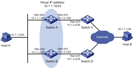
Networking and Configuration Requirements
l Host A needs to access Host B on the Internet. The default gateway of Host A is 10.1.1.10/24;
l Switch A and Switch B belong to VRRP group 1, whose virtual IP address is 10.1.1.10;
Applicable Product Matrix
|
Product series |
Software version |
Hardware version |
|
S5500-SI Series Ethernet Switches |
Release 1207 |
All versions except S5500-20TP-SI |
|
Release 1301 |
S5500-20TP-SI |
|
|
S5500-EI Series Ethernet Switches |
Release 2102 |
All versions |
|
S7500E Series Ethernet Switches |
Release 6300 |
All versions |
Configuration Procedure
1) Configure the IP address of each interface, as shown in Figure 1-1. The configuration procedure is omitted here.
2) Configure an NQA test group on Switch A.
<SwitchA> system-view
# Create an NQA test group with the administrator name admin and the operation tag test.
[SwitchA] nqa entry admin test
# Configure the test type as ICMP echo.
[SwitchA-nqa-admin-test] type icmp-echo
# Configure the destination address as 10.1.2.2.
[SwitchA-nqa-admin-test-icmp-echo] destination ip 10.1.2.2
# Set the test frequency to 100 ms.
[SwitchA-nqa-admin-test-icmp-echo] frequency 100
# Configure Reaction entry 1, specifying that five consecutive probe failures trigger the Track-NQA collaboration.
[SwitchA-nqa-admin-test-icmp-echo] reaction 1 checked-element probe-fail threshold-type consecutive 5 action-type trigger-only
[SwitchA-nqa-admin-test-icmp-echo] quit
# Start NQA probes.
[SwitchA] nqa schedule admin test start-time now lifetime forever
3) Configure a Track object on Switch A.
# Configure Track object 1, and associate it with Reaction entry 1 of the NQA test group (with the administrator admin, and the operation tag test).
[SwitchA] track 1 nqa entry admin test reaction 1
4) Configure VRRP on Switch A.
# Create VRRP group 1, and configure the virtual IP address 10.1.1.10 for the group.
[SwitchA] interface vlan-interface 2
[SwitchA-Vlan-interface2] vrrp vrid 1 virtual-ip 10.1.1.10
# Set the priority of Switch A in VRRP group 1 to 110.
[SwitchA-Vlan-interface2] vrrp vrid 1 priority 110
# Set the authentication mode of VRRP group 1 to simple, and the authentication key to hello.
[SwitchA-Vlan-interface2] vrrp vrid 1 authentication-mode simple hello
# Configure the master to send VRRP advertisements at an interval of five seconds.
[SwitchA-Vlan-interface2] vrrp vrid 1 timer advertise 5
# Configure Switch A to work in preemptive mode, and set the preemption delay to five seconds.
[SwitchA-Vlan-interface2] vrrp vrid 1 preempt-mode timer delay 5
# Configure to monitor Track object 1 and specify the priority decrement to 30.
[SwitchA-Vlan-interface2] vrrp vrid 1 track 1 reduced 30
5) Configure VRRP on Switch B.
<SwitchB> system-view
[SwitchB] interface vlan-interface 2
# Create VRRP group 1, and configure the virtual IP address 10.1.1.10 for the group.
[SwitchB-Vlan-interface2] vrrp vrid 1 virtual-ip 10.1.1.10
# Set the authentication mode of VRRP group 1 to simple, and the authentication key to hello.
[SwitchB-Vlan-interface2] vrrp vrid 1 authentication-mode simple hello
# Configure the master to send VRRP advertisements at an interval of five seconds.
[SwitchB-Vlan-interface2] vrrp vrid 1 timer advertise 5
# Configure Switch B to work in preemptive mode, and set the preemption delay to five seconds.
[SwitchB-Vlan-interface2] vrrp vrid 1 preempt-mode timer delay 5
6) Verify the configuration
After configuration, ping Host B on Host A, and you can see that Host B is reachable. Use the display vrrp command to view the configuration result.
# Display detailed information about VRRP group 1 on Switch A.
[SwitchA-Vlan-interface2] display vrrp verbose
IPv4 Standby Information:
Run Method : VIRTUAL-MAC
Virtual IP Ping : Enable
Interface : Vlan-interface2
VRID : 1 Adver. Timer : 5
Admin Status : UP State : Master
Config Pri : 110 Run Pri : 110
Preempt Mode : YES Delay Time : 5
Auth Type : SIMPLE TEXT Key : hello
Track Object : 1 Pri Reduced : 0
Virtual IP : 10.1.1.10
Virtual MAC : 0000-5e00-0101
Master IP : 10.1.1.1
# Display detailed information about VRRP group 1 on Switch B.
[SwitchB-Vlan-interface2] display vrrp verbose
IPv4 Standby Information:
Run Method : VIRTUAL-MAC
Virtual IP Ping : Enable
Interface : Vlan-interface2
VRID : 1 Adver. Timer : 5
Admin Status : UP State : Backup
Config Pri : 100 Run Pri : 100
Preempt Mode : YES Delay Time : 5
Auth Type : SIMPLE TEXT Key : hello
Virtual IP : 10.1.1.10
Master IP : 10.1.1.1
The above output information indicates that in VRRP group 1, Switch A is the master and Switch B is a backup. Packets from Host A to Host B are forwarded through Switch A.
When there is a fault on the link between Switch A and Switch C, you can still successfully ping Host B on Host A. Use the display vrrp command to view information about VRRP group 1.
# Display detailed information about VRRP group 1 on Switch A when there is a fault on the link between Switch A and Switch C.
[SwitchA-Vlan-interface2] display vrrp verbose
IPv4 Standby Information:
Run Method : VIRTUAL-MAC
Virtual IP Ping : Enable
Interface : Vlan-interface2
VRID : 1 Adver. Timer : 5
Admin Status : UP State : Backup
Config Pri : 110 Run Pri : 80
Preempt Mode : YES Delay Time : 5
Auth Type : SIMPLE TEXT Key : hello
Track Object : 1 Pri Reduced : 30
Virtual IP : 10.1.1.10
Master IP : 10.1.1.2
# Display detailed information about VRRP group 1 on Switch B when there is a fault on the link between Switch A and Switch C.
[SwitchB-Vlan-interface2] display vrrp verbose
IPv4 Standby Information:
Run Method : VIRTUAL-MAC
Virtual IP Ping : Enable
Interface : Vlan-interface2
VRID : 1 Adver. Timer : 5
Admin Status : UP State : Master
Config Pri : 100 Run Pri : 100
Preempt Mode : YES Delay Time : 5
Auth Type : SIMPLE TEXT Key : hello
Virtual IP : 10.1.1.10
Virtual MAC : 0000-5e00-0101
Master IP : 10.1.1.2
Complete Configuration
l Configuration on Switch A.
#
vlan 2 to 3
#
interface Vlan-interface2
ip address 10.1.1.1 255.255.255.0
vrrp vrid 1 virtual-ip 10.1.1.10
vrrp vrid 1 priority 110
vrrp vrid 1 preempt-mode timer delay 5
vrrp vrid 1 timer advertise 5
vrrp vrid 1 track 1 reduced 30
vrrp vrid 1 authentication-mode simple hello
#
interface Vlan-interface3
ip address 10.1.2.1 255.255.255.0
#
nqa entry admin test
type icmp-echo
destination ip 10.1.2.2
frequency 100
reaction 1 checked-element probe-fail threshold-type consecutive 5 action-type trigger-only
#
track 1 nqa entry admin test reaction 1
#
nqa schedule admin test start-time now lifetime forever
#
l Configuration on Switch B.
#
vlan 2
#
interface Vlan-interface2
vrrp vrid 1 virtual-ip 10.1.1.10
vrrp vrid 1 preempt-mode timer delay 5
vrrp vrid 1 timer advertise 5
vrrp vrid 1 authentication-mode simple hello
#
Configuration Guidelines
l Do not perform Track object monitoring on the IP address owner.
l When the status of the monitored Track object turns from Negative to Positive, the corresponding switch restores its priority automatically.
l The monitored Track object can be nonexistent, so that you can first specify the Track object to be monitored using the vrrp vrid track command, and then create the Track object using the track command.
Configuring Static Routing-Track-NQA Collaboration
Network Diagram
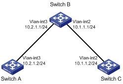
Figure 1-2 Network diagram for Static Routing-Track-NQA collaboration configuration
Networking and Configuration Requirements
l The next hop of the static route from Switch A to Switch C is Switch B.
l Configure Static Routing-Track-NQA collaboration on Switch A to implement real-time monitoring of the validity of the static route to Switch C.
Applicable Product Matrix
|
Software version |
Hardware version |
|
|
S5500-SI Series Ethernet Switches |
Release 1207 |
All versions except S5500-20TP-SI |
|
Release 1301 |
S5500-20TP-SI |
|
|
S5500-EI Series Ethernet Switches |
Release 2102 |
All versions |
|
S7500E Series Ethernet Switches |
Release 6300 |
All versions |
Configuration Procedure
1) Configure the IP address of each interface.
2) Configure a static route on Switch A and associate it with the Track object.
# Configure the address of the next hop of the static route to Switch C as 10.2.1.1, and configure the static route to associate with Track object 1.
<SwitchA> system-view
[SwitchA] ip route-static 10.1.1.2 24 10.2.1.1 track 1
3) Configure an NQA test group on Switch A.
# Create an NQA test group with the administrator admin and the operation tag test.
[SwitchA] nqa entry admin test
# Configure the test type as ICMP-echo.
[SwitchA-nqa-admin-test] type icmp-echo
# Configure the destination address as 10.2.1.1
[SwitchA-nqa-admin-test-icmp-echo] destination ip 10.2.1.1
# Configure the test frequency as 100 ms.
[SwitchA-nqa-admin-test-icmp-echo] frequency 100
# Configure Reaction entry 1, specifying that five consecutive probe failures trigger the Static Routing-Track-NQA collaboration.
[SwitchA-nqa-admin-test-icmp-echo] reaction 1 checked-element probe-fail threshold-type consecutive 5 action-type trigger-only
[SwitchA-nqa-admin-test-icmp-echo] quit
# Start NQA probes.
[SwitchA] nqa schedule admin test start-time now lifetime forever
4) Configure a Track object on Switch A.
# Configure Track object 1, and associate it with Reaction entry 1 of the NQA test group (with the administrator admin, and the operation tag test).
[SwitchA] track 1 nqa entry admin test reaction 1
5) Verify the configuration
# Display information of the Track object on Switch A.
[SwitchA] display track all
Track ID: 1
Status: Positive
Reference object:
NQA entry: admin test
Reaction: 1
# Display the routing table of Switch A.
[SwitchA] display ip routing-table
Routing Tables: Public
Destinations : 5 Routes : 5
Destination/Mask Proto Pre Cost NextHop Interface
10.1.1.0/24 Static 60 0 10.2.1.1 Vlan3
10.2.1.0/24 Direct 0 0 10.2.1.2 Vlan3
10.2.1.2/32 Direct 0 0 127.0.0.1 InLoop0
127.0.0.0/8 Direct 0 0 127.0.0.1 InLoop0
127.0.0.1/32 Direct 0 0 127.0.0.1 InLoop0
The output information above indicates the NQA test result, that is, the next hop 10.2.1.1 is reachable (the status of the Track object is Positive), and the configured static route is valid.
# Remove the IP address of interface VLAN-interface 3 on Switch B.
<SwitchB> system-view
[SwitchB] interface vlan-interface 3
[SwitchB-Vlan-interface3] undo ip address
# Display information of the Track object on Switch A.
[SwitchA] display track all
Track ID: 1
Status: Negative
Reference object:
NQA entry: admin test
Reaction: 1
# Display the routing table of Switch A.
[SwitchA] display ip routing-table
Routing Tables: Public
Destinations : 4 Routes : 4
Destination/Mask Proto Pre Cost NextHop Interface
10.2.1.0/24 Direct 0 0 10.2.1.2 Vlan3
10.2.1.2/32 Direct 0 0 127.0.0.1 InLoop0
127.0.0.0/8 Direct 0 0 127.0.0.1 InLoop0
127.0.0.1/32 Direct 0 0 127.0.0.1 InLoop0
The output information above indicates the NQA test result, that is, the next hop 10.2.1.1 is unreachable (the status of the Track object is Negative), and the configured static route is invalid.
Complete Configuration
l Configure Switch A.
#
vlan 3
#
interface Vlan-interface3
ip address 10.2.1.2 255.255.255.0
#
nqa entry admin test
type icmp-echo
destination ip 10.2.1.1
frequency 100
reaction 1 checked-element probe-fail threshold-type consecutive 5 action-type
trigger-only
#
ip route-static 10.1.1.0 255.255.255.0 10.2.1.1 track 1
#
track 1 nqa entry admin test reaction 1
#
nqa schedule admin test start-time now lifetime forever
#
Configuration Guidelines
None