- Table of Contents
-
- H3C Low-End and Mid-Range Ethernet Switches Configuration Examples(V1.01)
- 00-1Cover
- 01-Login Configuration Guide
- 02-VLAN Configuration Guide
- 03-GVRP Configuration Guide
- 04-Voice VLAN Configuration Guide
- 05-IP Addressing and Performance Configuration Guide
- 06-QinQ Configuration Guide
- 07-BPDU Tunnel Configuration Guide
- 08-VLAN Mapping Configuration Guide
- 09-MAC Address Table Management Configuration Guide
- 10-Link Aggregation Configuration Guide
- 11-IP Source Guard Configuration Guide
- 12-DLDP Configuration Guide
- 13-MSTP Configuration Guide
- 14-IPv4 Routing Configuration Guide
- 15-IPv6 Configuration Guide
- 16-IPv6 Routing Configuration Guide
- 17-IPv4 Multicast Configuration Guide
- 18-IPv6 Multicast Configuration Examples
- 19-802.1x Configuration Guide
- 20-AAA Configuration Guide
- 21-MAC Authentication Configuration Guide
- 22-Portal Configuration Guide
- 23-ARP Configuration Guide
- 24-DHCP Configuration Guide
- 25-ACL Configuration Guide
- 26-QoS Configuration Guide
- 27-Port Mirroring Configuration Guide
- 28-Cluster Management Configuration Guide
- 29-SNMP-RMON Configuration Guide
- 30-NTP Configuration Guide
- 31-FTP-TFTP Configuration Guide
- 32-UDP Helper Configuration Guide
- 33-Information Center Configuration Guide
- 34-DNS Configuration Guide
- 35-File System Management Configuration Guide
- 36-Remote Upgrade Configuration Guide
- 37-NQA Configuration Guide
- 38-VRRP Configuration Guide
- 39-SSH Configuration Guide
- 40-Port Security Configuration Guide
- 41-Port Isolation Configuration Guide
- 42-LLDP Configuration Guide
- 43-MCE Configuration Guide
- 44-PoE Configuration Guide
- 45-OAM Configuration Guide
- 46-Connectivity Fault Detection Configuration Guide
- 47-RRPP Configuration Guide
- 48-sFlow Configuration Guide
- 49-SSL-HTTPS Configuration Guide
- 50-PKI Configuration Guide
- 51-Track Configuration Guide
- 52-EPON-OLT Configuration Guide
- 53-Smart Link Configuration Guide
- 54-MPLS Configuration Guide
- Related Documents
-
| Title | Size | Download |
|---|---|---|
| 23-ARP Configuration Guide | 88.76 KB |
Networking and Configuration Requirements
Networking and Configuration Requirements
Networking and Configuration Requirements
ARP Detection Configuration Example
Configuring ARP Basics
Network Diagram
None
Networking and Configuration Requirements
l Set the aging time for dynamic ARP entries to 10 minutes.
l Set the maximum number of dynamic ARP entries that VLAN-interface 10 can learn to 1000.
l Add a permanent static ARP entry, with the IP address being 192.168.1.1/24, the MAC address being 000f-e201-0000, and the outbound port being GigabitEthernet 1/0/10 of VLAN 10.
l Add a non-permanent static ARP entry, with the IP address being 192.168.1.2/24, the MAC address being 000f-e201-0001.
Applicable Product Matrix
|
Product series |
Software version |
Hardware version |
|
S3610 Series Ethernet Switches |
Release 5301 Release 5303 |
All versions |
|
S5510 Series Ethernet Switches |
Release 5301 Release 5303 |
All versions |
|
S5500-SI Series Ethernet Switches |
Release 1207 |
All versions except S5500-20TP-SI |
|
Release 1301 |
S5500-20TP-SI |
|
|
S5500-EI Series Ethernet Switches |
Release 2102 |
All versions |
|
S7500E Series Ethernet Switches |
Release 6100 Release 6300 |
All versions |
|
S3500-EA Series Ethernet Switches |
Release 5303 |
All versions |
Configuration Procedure
# Set the aging time for dynamic ARP entries to 10 minutes.
[Switch] arp timer aging 10
# Set the maximum number of dynamic ARP entries that VLAN-interface 10 can learn to 1000.
[Switch] vlan 10
[Switch-vlan10] quit
[Switch-GigabitEthernet1/0/10] port access vlan 10
[Switch-GigabitEthernet1/0/10] quit
[Switch] interface vlan-interface 10
[Switch-vlan-interface10] arp max-learning-num 1000
[Switch-vlan-interface10] quit
# Add a permanent static ARP entry.
[Switch] arp static 192.168.1.1 000f-e201-0000 10 gigabitethernet1/0/10
# Add a non-permanent static ARP entry.
[Switch] arp static 192.168.1.2 000f-e201-0001
Complete Configuration
#
vlan 10
#
interface Vlan-interface10
arp max-learning-num 1000
#
interface GigabitEthernet1/0/10
port access vlan 10
#
arp timer aging 10
arp static 192.168.1.1 000f-e201-0000 10 GigabitEthernet1/0/10
arp static 192.168.1.2 000f-e201-0001
#
Configuration Guidelines
None
Configuring Proxy ARP
Network Diagram
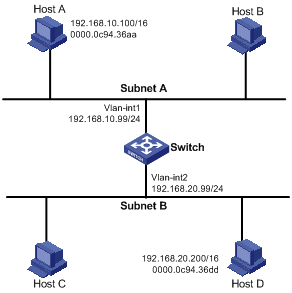
Figure 1-1 Network diagram for proxy ARP
Networking and Configuration Requirements
l Host A that belongs to VLAN 1 has an IP address of 192.168.10.100/16; Host D that belongs to VLAN 2 has an IP address of 192.168.20.200/16.
l Configure proxy ARP on the switch to enable communication between Host A and Host D.
Applicable Product Matrix
|
Product series |
Software version |
Hardware version |
|
S3610 Series Ethernet Switches |
Release 5301 Release 5303 |
All versions |
|
S5510 Series Ethernet Switches |
Release 5301 Release 5303 |
All versions |
|
S5500-SI Series Ethernet Switches |
Release 1207 |
All versions except S5500-20TP-SI |
|
Release 1301 |
S5500-20TP-SI |
|
|
S5500-EI Series Ethernet Switches |
Release 2102 |
All versions |
|
S7500E Series Ethernet Switches |
Release 6100 Release 6300 |
All versions |
|
S3500-EA Series Ethernet Switches |
Release 5303 |
All versions |
Configuration Procedure
# Configure the IP address of VLAN-interface 1 and then enable proxy ARP on the interface.
<Switch> system-view
[Switch] interface vlan-interface 1
[Switch-Vlan-interface1] ip address 192.168.10.99 255.255.255.0
[Switch-Vlan-interface1] proxy-arp enable
[Switch-Vlan-interface1] quit
# Configure the IP address of VLAN-interface 2 and then enable proxy ARP on the interface.
[Switch] interface vlan-interface 2
[Switch-Vlan-interface2] ip address 192.168.20.99 255.255.255.0
[Switch-Vlan-interface2] proxy-arp enable
[Switch-Vlan-interface2] quit
Complete Configuration
#
interface Vlan-interface1
ip address 192.168.10.99 255.255.255.0
proxy-arp enable
#
interface Vlan-interface2
ip address 192.168.20.99 255.255.255.0
proxy-arp enable
#
Configuration Guidelines
None
Configuring Local Proxy ARP
Network Diagram
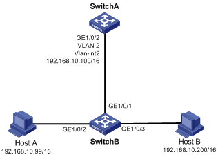
Figure 1-2 Network diagram for local proxy ARP between isolated ports
Networking and Configuration Requirements
l Host A and Host B belong to the same VLAN, and are connected to GigabitEthernet 1/0/2 and GigabitEthernet 1/0/3 of Switch B respectively.
l Switch B is connected to Switch A via GigabitEthernet 1/0/1.
l On Switch B, Layer 2 and Layer 3 port isolation are configured on GigabitEthernet 1/0/2 and GigabitEthernet 1/0/3. Enable proxy ARP on Switch A to allow communication between Host A and Host B.
Applicable Product Matrix
|
Product series |
Software version |
Hardware version |
|
S3610 Series Ethernet Switches |
Release 5301 Release 5303 |
All versions |
|
S5510 Series Ethernet Switches |
Release 5301 Release 5303 |
All versions |
|
S5500-SI Series Ethernet Switches |
Release 1207 |
All versions except S5500-20TP-SI |
|
Release 1301 |
S5500-20TP-SI |
|
|
S5500-EI Series Ethernet Switches |
Release 2102 |
All versions |
|
S7500E Series Ethernet Switches |
Release 6100 Release 6300 |
All versions |
|
S3500-EA Series Ethernet Switches |
Release 5303 |
All versions |
Configuration Procedure
# Add GigabitEthernet 1/0/1, GigabitEthernet 1/0/2 and GigabitEthernet 1/0/3 to VLAN 2.
<SwitchB> system-view
[SwitchB] vlan 2
[SwitchB-vlan2] port gigabitethernet 1/0/1
[SwitchB-vlan2] port gigabitethernet 1/0/2
[SwitchB-vlan2] port gigabitethernet 1/0/3
[SwitchB-vlan2] quit
# Isolate GigabitEthernet 1/0/2 from GigabitEthernet 1/0/3 at Layer 2.
[SwitchB] interface gigabitethernet 1/0/2
[SwitchB-GigabitEthernet1/0/2] port-isolate enable
[SwitchB-GigabitEthernet1/0/2] quit
[SwitchB] interface gigabitethernet 1/0/3
[SwitchB-GigabitEthernet1/0/3] port-isolate enable
[SwitchB-GigabitEthernet1/0/3] quit
# Configure an IP address for VLAN-interface 2 on Switch A.
[SwitchA] vlan 2
[SwitchA-vlan2] port gigabitethernet 1/0/2
[SwitchA-vlan2] quit
[SwitchA] interface vlan-interface 2
[SwitchA-Vlan-interface2] ip address 192.168.10.100 255.255.0.0
# Enable local proxy ARP to let Host A and Host B communicate at Layer 3.
[SwitchA-Vlan-interface2] local-proxy-arp enable
[SwitchA-Vlan-interface2] quit
Complete Configuration
l Configure Switch B
#
vlan 2
#
interface GigabitEthernet1/0/1
port access vlan 2
#
interface GigabitEthernet1/0/2
port access vlan 2
port-isolate enable
#
interface GigabitEthernet1/0/3
port access vlan 2
port-isolate enable
#
l Configure Switch A
#
vlan 2
#
interface GigabitEthernet1/0/2
port access vlan 2
#
interface Vlan-interface2
ip address 192.168.10.100 255.255.0.0
local-proxy-arp enable
#
Configuration Guidelines
l For details about port isolation, refer to Port Isolation Configuration Guide.
l If Switch B has Layer 2 and Layer 3 port isolation configured, you need to configure local proxy ARP on the VLAN-interface 2 of Switch A to enable communication between Host A and Host B, as shown in Figure 1-2.
l If Switch B (S3610&S5510 series Ethernet switches, for example) has only Layer 2 port isolation configured, you can enable communication between the two hosts by configuring local proxy ARP directly on VLAN-interface 2 of Switch B.
ARP Detection Configuration Example
Network diagram
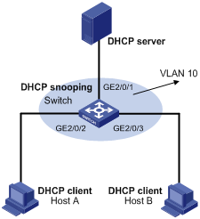
Figure 1-3 Network diagram for ARP detection configuration
Network requirements
l Enable DHCP snooping on Switch. Enable ARP detection for VLAN 10 to allow only packets from valid clients to pass.
l Configure Host A and Host B as DHCP clients.
Applicable Product Matrix
|
Product series |
Software version |
Hardware version |
|
S7500E Series Ethernet Switches |
Release 6100 Release 6300 |
All versions |
Configuration Procedure
1) Configure a DHCP server (the configuration procedure is omitted).
2) Configure Host A and Host B as DHCP clients (the configuration procedure is omitted).
3) Configure Switch
# Add all the ports on the Switch into VLAN 10 (the configuration procedure is omitted).
# Enable DHCP snooping.
<Switch> system-view
[Switch] dhcp-snooping
[Switch] interface gigabitethernet 2/0/1
[Switch-GigabitEthernet2/0/1] dhcp-snooping trust
[Switch-GigabitEthernet2/0/1] quit
# Enable ARP detection for VLAN 10. Configure the upstream port as a trusted port and the downstream ports as untrusted ports (a port is an untrusted port by default).
[Switch] vlan 10
[Switch-vlan10] arp detection enable
[Switch-vlan10] interface gigabitethernet 2/0/1
[Switch-GigabitEthernet2/0/1] arp detection trust
[Switch-GigabitEthernet2/0/1] quit
# Enable the checking of the MAC addresses and IP addresses of ARP packets.
[Switch] arp detection validate dst-mac ip src-mac
# Specify the ARP packet rate on GigabitEthernet2/0/2 and GigabitEthernet2/0/3 as 150 pps.
[Switch] interface GigabitEthernet2/0/2
[Switch-GigabitEthernet2/0/2] arp rate-limit rate 150 drop
[Switch-GigabitEthernet2/0/2] quit
[Switch] interface gigabitethernet 2/0/3
[Switch-GigabitEthernet2/0/3] arp rate-limit rate 150 drop
[Switch-GigabitEthernet2/0/3] quit
Complete Configuration
#
dhcp-snooping
#
interface GigabitEthernet2/0/1
dhcp-snooping trust
arp detection trust
#
vlan 10
arp detection enable
#
interface GigabitEthernet2/0/2
arp rate-limit rate 150 drop
#
interface GigabitEthernet2/0/3
arp rate-limit rate 150 drop
#
arp detection validate dst-mac ip src-mac
#
Configuration Guidelines
None.