- Table of Contents
-
- H3C Low-End and Mid-Range Ethernet Switches Configuration Examples(V1.01)
- 00-1Cover
- 01-Login Configuration Guide
- 02-VLAN Configuration Guide
- 03-GVRP Configuration Guide
- 04-Voice VLAN Configuration Guide
- 05-IP Addressing and Performance Configuration Guide
- 06-QinQ Configuration Guide
- 07-BPDU Tunnel Configuration Guide
- 08-VLAN Mapping Configuration Guide
- 09-MAC Address Table Management Configuration Guide
- 10-Link Aggregation Configuration Guide
- 11-IP Source Guard Configuration Guide
- 12-DLDP Configuration Guide
- 13-MSTP Configuration Guide
- 14-IPv4 Routing Configuration Guide
- 15-IPv6 Configuration Guide
- 16-IPv6 Routing Configuration Guide
- 17-IPv4 Multicast Configuration Guide
- 18-IPv6 Multicast Configuration Examples
- 19-802.1x Configuration Guide
- 20-AAA Configuration Guide
- 21-MAC Authentication Configuration Guide
- 22-Portal Configuration Guide
- 23-ARP Configuration Guide
- 24-DHCP Configuration Guide
- 25-ACL Configuration Guide
- 26-QoS Configuration Guide
- 27-Port Mirroring Configuration Guide
- 28-Cluster Management Configuration Guide
- 29-SNMP-RMON Configuration Guide
- 30-NTP Configuration Guide
- 31-FTP-TFTP Configuration Guide
- 32-UDP Helper Configuration Guide
- 33-Information Center Configuration Guide
- 34-DNS Configuration Guide
- 35-File System Management Configuration Guide
- 36-Remote Upgrade Configuration Guide
- 37-NQA Configuration Guide
- 38-VRRP Configuration Guide
- 39-SSH Configuration Guide
- 40-Port Security Configuration Guide
- 41-Port Isolation Configuration Guide
- 42-LLDP Configuration Guide
- 43-MCE Configuration Guide
- 44-PoE Configuration Guide
- 45-OAM Configuration Guide
- 46-Connectivity Fault Detection Configuration Guide
- 47-RRPP Configuration Guide
- 48-sFlow Configuration Guide
- 49-SSL-HTTPS Configuration Guide
- 50-PKI Configuration Guide
- 51-Track Configuration Guide
- 52-EPON-OLT Configuration Guide
- 53-Smart Link Configuration Guide
- 54-MPLS Configuration Guide
- Related Documents
-
| Title | Size | Download |
|---|---|---|
| 19-802.1x Configuration Guide | 134.65 KB |
Networking and Configuration Requirements
Configuring Dynamic VLAN Assignment
Networking and Configuration Requirements
Networking and Configuration Requirements
Configuring EAD Fast Deployment
Networking and Configuration Requirements
802.1x Overview
The 802.1x protocol was proposed by IEEE 802 LAN/WAN committee for security of wireless LANs (WLANs). However, it has been widely used on Ethernets as a common port access control mechanism.
As a port-based access control protocol, 802.1x authenticates and controls supplicants at the port level. A supplicant connected to an 802.1x-enabled port of an access control device can access the resources on the LAN only after passing authentication.
Configuring 802.1x
Network Diagram
Figure 1-1 Configure 802.1x (using a RADIUS server for AAA services)
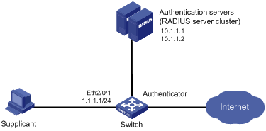
Networking and Configuration Requirements
l The access control method of macbased is required on the port to control supplicants.
l All supplicants belong to default domain aabbcc.net, which can accommodate up to 30 users. RADIUS authentication is performed at first, and then local authentication when no response from the RADIUS server is received. If the RADIUS accounting fails, the authenticator gets users offline.
l A server cluster with two RADIUS servers is connected to the switch. The IP addresses of the servers are 10.1.1.1 and 10.1.1.2 respectively. Use the former as the primary authentication/secondary accounting server, and the latter as the secondary authentication/primary accounting server.
l Set the shared key for the switch to exchange packets with the authentication server as name, and that for the switch to exchange packets with the accounting server as money.
l Configure the switch to try up to five times at an interval of 5 seconds in transmitting a packet to the RADIUS server until it receives a response from the server, and to send real time accounting packets to the accounting server every 15 minutes.
l Configure the switch to remove the domain name from the username before passing the username to the RADIUS server.
l Set the username of the 802.1x user as localuser and the password as localpass and specify to use plain text mode. Enable the idle cut function to get the user offline whenever the user remains idle for over 20 minutes.
Applicable Product Matrix
|
Product series |
Software version |
Hardware version |
|
S3610 Series Ethernet Switches |
Release 5301, Release 5303 |
All versions |
|
S5510 Series Ethernet Switches |
Release 5301, Release 5303 |
All versions |
|
S5500-SI Series Ethernet Switches |
Release 1207 |
All versions except S5500-20TP-SI |
|
Release 1301 |
S5500-20TP-SI |
|
|
S5500-EI Series Ethernet Switches |
Release 2102 |
All versions |
|
S7500E Series Ethernet Switches |
Release 6100, Release 6300 |
All versions |
Configuration Procedure
# Assign IP addresses to the interfaces. (Omitted)
# Add local user localuser, enable the idle cut function, and set the maximum allowed idle duration.
<Sysname> system-view
[Sysname] local-user localuser
[Sysname-luser-localuser] service-type lan-access
[Sysname-luser-localuser] password simple localpass
[Sysname-luser-localuser] attribute idle-cut 20
[Sysname-luser-localuser] quit
# Create RADIUS scheme radius1 and enter its view.
[Sysname] radius scheme radius1
# Configure the IP addresses of the primary authentication and accounting RADIUS servers.
[Sysname-radius-radius1] primary authentication 10.1.1.1
[Sysname-radius-radius1] primary accounting 10.1.1.2
# Configure the IP addresses of the secondary authentication and accounting RADIUS servers.
[Sysname-radius-radius1] secondary authentication 10.1.1.2
[Sysname-radius-radius1] secondary accounting 10.1.1.1
# Specify the shared key for the device to exchange packets with the authentication server.
[Sysname-radius-radius1] key authentication name
# Specify the shared key for the device to exchange packets with the accounting server.
[Sysname-radius-radius1] key accounting money
# Set the interval for the device to retransmit packets to the RADIUS server and the maximum number of transmission attempts.
[Sysname-radius-radius1] timer response-timeout 5
[Sysname-radius-radius1] retry 5
# Set the interval for the device to send real time accounting packets to the RADIUS server.
[Sysname-radius-radius1] timer realtime-accounting 15
# Specify the device to remove the domain name of each username before passing the username to the RADIUS server.
[Sysname-radius-radius1] user-name-format without-domain
[Sysname-radius-radius1] quit
# Create domain aabbcc.net and enter its view.
[Sysname] domain aabbcc.net
# Set radius1 as the RADIUS scheme for users of the domain and specify to use local authentication as the secondary scheme.
[Sysname-isp-aabbcc.net] authentication default radius-scheme radius1 local
[Sysname-isp-aabbcc.net] authorization default radius-scheme radius1 local
[Sysname-isp-aabbcc.net] accounting default radius-scheme radius1 local
# Set the maximum number of users for the domain as 30.
[Sysname-isp-aabbcc.net] access-limit enable 30
# Enable the idle cut function and set the maximum allowed idle duration.
[Sysname-isp-aabbcc.net] idle-cut enable 20
[Sysname-isp-aabbcc.net] quit
# Configure aabbcc.net as the default domain.
[Sysname] domain default enable aabbcc.net
[Sysname] dot1x
# Enable 802.1x for port Ethernet 2/0/1.
[Sysname] interface Ethernet 2/0/1
[Sysname-Ethernet2/0/1] dot1x
[Sysname-Ethernet2/0/1] quit
# Set the port access control method to macbased. (Optional. The default answers the requirement.)
[Sysname] dot1x port-method macbased interface Ethernet 2/0/1
Complete Configuration
#
domain default enable aabbcc.net
#
dot1x
#
radius scheme radius1
primary authentication 10.1.1.1
primary accounting 10.1.1.2
secondary authentication 10.1.1.2
secondary accounting 10.1.1.1
key authentication name
key accounting money
timer realtime-accounting 15
timer response-timeout 5
user-name-format without-domain
retry 5
#
domain aabbcc.net
authentication default radius-scheme radius1 local
authorization default radius-scheme radius1 local
accounting default radius-scheme radius1 local
access-limit enable 30
#
local-user localuser
password simple localpass
service-type lan-access
attribute idle-cut 20
#
interface Ethernet2/0/1
dot1x
#
Configuration Guidelines
l For 802.1x to take effect on a port, you must enable it both globally in system view and for the port in system view or Ethernet interface view.
l 802.1x timers only need to be changed in special or extreme network environments. For example, you can give the client timeout timer a higher value in a low-performance network, give the quiet timer a higher value in a vulnerable network or a lower value for quicker authentication response, or adjust the server timeout timer to suit the performance of the authentication server.
l In EAP relay authentication mode, the device encapsulates the 802.1x user information in the EAP attributes of RADIUS packets and sends the packets to the RADIUS server for authentication. In this case, you can configure the user-name-format command but it does not take effect.
Configuring Dynamic VLAN Assignment
Network Diagram
Figure 1-2 Network diagram for dynamic VLAN assignment configuration
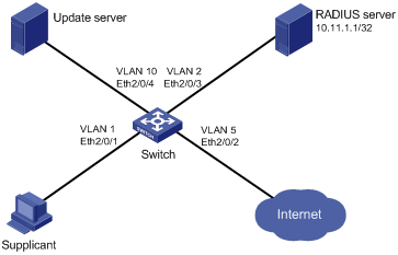
Networking and Configuration Requirements
l The host (Supplicant in the above figure) must pass 802.1x authentication to access the Internet. The authentication server is a RADIUS server, which supports dynamic assignment of VLANs. Set the shared key for the switch to exchange packets with the RADIUS server to abc.
l The update server, which is in VLAN 10, is for client software download and upgrade.
l Port Ethernet 2/0/2 of the switch, which is in VLAN 5, is for accessing the Internet.
l If the switch sends out EAP-Request/Identity packets from port Ethernet 2/0/1 for the maximum times but gets no response, the switch adds Ethernet 2/0/1 into the guest VLAN. In this case, both the supplicant and the update server are in VLAN 10, and the supplicant can access the update server and download the 802.1x client.
l After the supplicant passes authentication, the authentication server assigns VLAN 5 to the supplicant. As port Ethernet 2/0/5 is also in VLAN 5, the supplicant can access the Internet then.
Applicable Product Matrix
|
Product series |
Software version |
Hardware version |
|
S3610 Series Ethernet Switches |
Release 5301, Release 5303 |
All versions |
|
S5510 Series Ethernet Switches |
Release 5301, Release 5303 |
All versions |
|
S5500-SI Series Ethernet Switches |
Release 1207 |
All versions except S5500-20TP-SI |
|
Release 1301 |
S5500-20TP-SI |
|
|
S5500-EI Series Ethernet Switches |
Release 2102 |
All versions |
|
S7500E Series Ethernet Switches |
Release 6100, Release 6300 |
All versions |
Configuration Procedure
# Configure RADIUS scheme 2000.
<Sysname> system-view
[Sysname] radius scheme 2000
[Sysname-radius-2000] primary authentication 10.11.1.1 1812
[Sysname-radius-2000] primary accounting 10.11.1.1 1813
[Sysname-radius-2000] key authentication abc
[Sysname-radius-2000] key accounting abc
[Sysname-radius-2000] user-name-format without-domain
[Sysname-radius-2000] quit
# Configure domain system and specify to use RADIUS scheme 2000 for users of the domain.
[Sysname] domain system
[Sysname-isp-system] authentication default radius-scheme 2000
[Sysname-isp-system] authorization default radius-scheme 2000
[Sysname-isp-system] accounting default radius-scheme 2000
[Sysname-isp-system] quit
# Enable 802.1x globally.
[Sysname] dot1x
# Enable 802.1x for port Ethernet 2/0/1.
[Sysname] interface Ethernet 2/0/1
[Sysname-Ethernet2/0/1] dot1x
# Set the port access control method to portbased.
[Sysname-Ethernet2/0/1] dot1x port-method portbased
# Set the port access control mode to auto.
[Sysname-Ethernet2/0/1] dot1x port-control auto
[Sysname-Ethernet2/0/1] quit
# Create VLAN 10.
[Sysname] vlan 10
[Sysname-vlan10] quit
# Specify port Ethernet 2/0/1 to use VLAN 10 as its guest VLAN.
[Sysname] dot1x guest-vlan 10 interface Ethernet 2/0/1
In the case that the client fails to pass the authentication, fails to get online, or goes offline, the server should send the EAP-Request/Identity packets for the maximum times and assign the guest VLAN to the client. You can use the display vlan 10 command to see whether the guest VLAN configuration takes effect.
After the client successfully gets online, you can use the display vlan 5 command to see whether the VLAN dynamically assigned by the server has taken effect.
Complete Configuration
#
radius scheme 2000
primary authentication 10.11.1.1 1812
primary accounting 10.11.1.1 1813
key authentication abc
key accounting abc
user-name-format without-domain
#
domain system
authentication default radius-scheme 2000
authorization default radius-scheme 2000
accounting default radius-scheme 2000
#
dot1x
dot1x guest-vlan 10 interface Ethernet 2/0/1
#
interface Ethernet 2/0/1
dot1x
dot1x port-method portbased
dot1x port-control auto
quit
#
vlan 10
Configuration Guidelines
l If a port’s access control method is portbased, its guest VLAN can take effect; if a port’s access control method is macbased, its guest VLAN can be configured but cannot take effect.
l The 802.1x multicast trigger function must be enabled for the Guest VLAN function to take effect.
l A super VLAN cannot be set as the guest VLAN. Similarly, a guest VLAN cannot be set as the super VLAN.
l You can specify a tagged VLAN as the guest VLAN for a Hybrid port, but the guest VLAN does not take effect. Similarly, if a guest VLAN for a Hybrid port is in operation, you cannot configure the guest VLAN as a tagged VLAN on the port.
l A port can be configured with only one guest VLAN. But different ports can have different guest VLANs.
l If the data flows from a user-side device include VLAN tags, and 802.1x and guest VLAN are enabled on the access port, you are recommended to configure different VLAN IDs for the Voice VLAN, the default port VLAN, and the guest VLAN of 802.1x.
Configuring ACL Assignment
Network Diagram
Figure 1-3 Network diagram for ACL assignment configuration
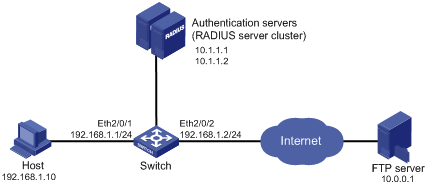
Networking and Configuration Requirements
As shown in Figure 1-3, a host is connected to port Ethernet 2/0/1 of the switch and must pass 802.1x authentication to access the Internet. An RADIUS server cluster takes the responsibility of authentication. An FTP server with the IP address 10.0.0.1 is on the Internet.
l On port Ethernet 2/0/1 of the switch, enable 802.1x authentication and configure ACL 3000.
l Configure the authentication server to assign ACL 3000 to the switch as the authorization ACL after the host passes authentication, so that the host can access the Internet but cannot access the FTP server.
Applicable Product Matrix
|
Product series |
Software version |
Hardware version |
|
S3610 Series Ethernet Switches |
Release 5301, Release 5303 |
All versions |
|
S5510 Series Ethernet Switches |
Release 5301, Release 5303 |
All versions |
|
S5500-SI Series Ethernet Switches |
Release 1207 |
All versions except S5500-20TP-SI |
|
Release 1301 |
S5500-20TP-SI |
|
|
S5500-EI Series Ethernet Switches |
Release 2102 |
All versions |
|
S7500E Series Ethernet Switches |
Release 6100, Release 6300 |
All versions |
Configuration Procedure
1) Configure ACL assignment on Switch
# Configure the IP addresses of the interfaces. (Omitted)
# Configure the RADIUS scheme.
<Sysname> system-view
[Sysname] radius scheme 2000
[Sysname-radius-2000] primary authentication 10.1.1.1 1812
[Sysname-radius-2000] primary accounting 10.1.1.2 1813
[Sysname-radius-2000] key authentication abc
[Sysname-radius-2000] key accounting abc
[Sysname-radius-2000] user-name-format without-domain
[Sysname-radius-2000] quit
# Create an ISP domain and specify the AAA schemes.
[Sysname] domain 2000
[Sysname-isp-2000] authentication default radius-scheme 2000
[Sysname-isp-2000] authorization default radius-scheme 2000
[Sysname-isp-2000] accounting default radius-scheme 2000
[Sysname-isp-2000] quit
# Configure ACL 3000 to deny packets destined for 10.0.0.1.
[Sysname] acl number 3000
[Sysname-acl-adv-3000] rule 0 deny ip destination 10.0.0.1 0
# Enable 802.1x globally.
[Sysname] dot1x
# Enable 802.1x for port Ethernet 2/0/1.
[Sysname] interface Ethernet 2/0/1
[Sysname-Ethernet2/0/1] dot1x
Complete Configuration
#
dot1x
#
radius scheme 2000
primary authentication 10.1.1.1
primary accounting 10.1.1.2
key authentication abc
key accounting abc
user-name-format without-domain
#
domain 2000
authentication default radius-scheme 2000
authorization default radius-scheme 2000
accounting default radius-scheme 2000
#
acl number 3000
rule 0 deny ip destination 10.0.0.1 0
#
interface Ethernet2/0/1
dot1x
#
Configuration Guidelines
l Before configuring the server to assign an ACL as the authorization ACL, you need to configure the ACL on the switch.
l You can change a user’s access right by changing the authorization ACL to be assigned to the user on the server or modifying the rules of the ACL on the switch.
Configuring EAD Fast Deployment
As an integrated security scheme, an endpoint admission defense (EAD) scheme can improve the overall defense capability of a network. However, EAD deployment brings much workload in actual applications.
To address the issue, the H3C series switch provides the forcible deployment of EAD clients with 802.1x authentication, easing the work of EAD client deployment.
Network Diagram
Figure 1-4 Network diagram for EAD Fast Deployment configuration
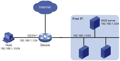
Networking and Configuration Requirements
As shown in Figure 1-4, the host is connected to the device, and the device is connected to the freely accessible network segment and outside network.
It is required that:
l Before successful 802.1x authentication, the host using WEB Browser to access outside network will be redirected to the WEB server, and it can download and install 802.1x client software.
l After successful 802.1x authentication, the host can access outside network.
Applicable Product Matrix
|
Product series |
Software version |
Hardware version |
|
S3610 Series Ethernet Switches |
Release 5301, Release 5303 |
All versions |
|
S5510 Series Ethernet Switches |
Release 5301, Release 5303 |
All versions |
|
S5500-SI Series Ethernet Switches |
Release 1207 |
All versions except S5500-20TP-SI |
|
Release 1301 |
S5500-20TP-SI |
|
|
S5500-EI Series Ethernet Switches |
Release 2102 |
All versions |
|
S7500E Series Ethernet Switches |
Release 6100, Release 6300 |
All versions |
Configuration Procedure
1) Configure the WEB server
Before using the EAD fast deployment function, you need to configure the WEB server to provide the download service of 802.1x client software.
2) Configure the device to support EAD fast deployment
# Configure the IP addresses of the interfaces (omitted).
# Configure the free IP.
<Device> system-view
[Device] dot1x free-ip 192.168.1.0 24
# Configure the redirect URL for client software download.
[Device] dot1x url http://192.168.1.3
# Enable 802.1x globally.
[Device] dot1x
# Enable 802.1x on the port.
[Device] interface GigabitEthernet 2/0/1
[Device -GigabitEthernet2/0/1] dot1x
Before passing the 802.1x authentication, if the user uses WEB Browser to access any external website, the user will be taken to the WEB server, which provides the client software download service.
Complete Configuration
#
dot1x
dot1x url http://192.168.1.3
dot1x free-ip 192.168.1.0 255.255.255.0
#
interface GigabitEthernet2/0/1
dot1x
#
Configuration Guidelines
l Currently, MAC authentication and port security cannot work together with EAD fast deployment. Once MAC authentication or port security is enabled globally, the EAD fast deployment is disabled automatically.
l You cannot configure both the free IP and the MAC authentication/802.1x guest VLAN function on a port.
l If no freely accessible network segment is configured, a user cannot obtain a dynamic IP address before passing 802.1x authentication. To solve this problem, you can configure a freely accessible network segment that is on the same network segment with the DHCP server.
l To redirect to the WEB server, enter an IP address that is not within the freely accessible network segment in dotted decimal notation (X.X.X.X).