- Table of Contents
-
- H3C Low-End and Mid-Range Ethernet Switches Configuration Examples(V1.01)
- 00-1Cover
- 01-Login Configuration Guide
- 02-VLAN Configuration Guide
- 03-GVRP Configuration Guide
- 04-Voice VLAN Configuration Guide
- 05-IP Addressing and Performance Configuration Guide
- 06-QinQ Configuration Guide
- 07-BPDU Tunnel Configuration Guide
- 08-VLAN Mapping Configuration Guide
- 09-MAC Address Table Management Configuration Guide
- 10-Link Aggregation Configuration Guide
- 11-IP Source Guard Configuration Guide
- 12-DLDP Configuration Guide
- 13-MSTP Configuration Guide
- 14-IPv4 Routing Configuration Guide
- 15-IPv6 Configuration Guide
- 16-IPv6 Routing Configuration Guide
- 17-IPv4 Multicast Configuration Guide
- 18-IPv6 Multicast Configuration Examples
- 19-802.1x Configuration Guide
- 20-AAA Configuration Guide
- 21-MAC Authentication Configuration Guide
- 22-Portal Configuration Guide
- 23-ARP Configuration Guide
- 24-DHCP Configuration Guide
- 25-ACL Configuration Guide
- 26-QoS Configuration Guide
- 27-Port Mirroring Configuration Guide
- 28-Cluster Management Configuration Guide
- 29-SNMP-RMON Configuration Guide
- 30-NTP Configuration Guide
- 31-FTP-TFTP Configuration Guide
- 32-UDP Helper Configuration Guide
- 33-Information Center Configuration Guide
- 34-DNS Configuration Guide
- 35-File System Management Configuration Guide
- 36-Remote Upgrade Configuration Guide
- 37-NQA Configuration Guide
- 38-VRRP Configuration Guide
- 39-SSH Configuration Guide
- 40-Port Security Configuration Guide
- 41-Port Isolation Configuration Guide
- 42-LLDP Configuration Guide
- 43-MCE Configuration Guide
- 44-PoE Configuration Guide
- 45-OAM Configuration Guide
- 46-Connectivity Fault Detection Configuration Guide
- 47-RRPP Configuration Guide
- 48-sFlow Configuration Guide
- 49-SSL-HTTPS Configuration Guide
- 50-PKI Configuration Guide
- 51-Track Configuration Guide
- 52-EPON-OLT Configuration Guide
- 53-Smart Link Configuration Guide
- 54-MPLS Configuration Guide
- Related Documents
-
| Title | Size | Download |
|---|---|---|
| 30-NTP Configuration Guide | 137.88 KB |
Configuring NTP Client/Server Mode
Networking and Configuration Requirements
Configuring NTP Symmetric Peers Mode
Networking and Configuration Requirements
Configuring NTP Broadcast Mode
Networking and Configuration Requirements
Configuring NTP Multicast Mode
Networking and Configuration Requirements
Configuring NTP Broadcast Mode with Authentication
Networking and Configuration Requirements
NTP Overview
Defined in RFC 1305, the Network Time Protocol (NTP) synchronizes timekeeping among distributed time servers and clients. NTP runs over the User Datagram Protocol (UDP), using UDP port 123.
The purpose of using NTP is to keep consistent timekeeping among all clock-dependent devices within the network, so that the devices can provide diverse applications based on the consistent time.
For a local system running NTP, its time can be synchronized by other reference sources and can be used as a reference source to synchronize other clocks.
Configuring NTP Client/Server Mode
Network Diagram
Figure 1-1 Network diagram for NTP client/server mode configuration
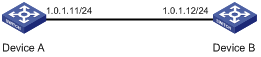
Networking and Configuration Requirements
l The local clock of Device A is to be used as a reference source, with the stratum level of 2.
l Device B works in the client/server mode and Device A is to be used as the NTP server of Device B.
Applicable Product Matrix
|
Product series |
Software version |
Hardware version |
|
S3610 Series Ethernet Switches |
Release 5301 Release 5303 |
All versions |
|
S5510 Series Ethernet Switches |
Release 5301 Release 5303 |
All versions |
|
S5500-SI Series Ethernet Switches |
Release 1207 |
All versions except S5500-20TP-SI |
|
Release 1301 |
S5500-20TP-SI |
|
|
S5500-EI Series Ethernet Switches |
Release 2102 |
All versions |
|
S7500E Series Ethernet Switches |
Release 6100 Release 6300 |
All versions |
|
S3500-EA Series Ethernet Switches |
Release 5303 |
All versions |
Configuration Procedure
l Configure Device A
# Specify the local clock as the reference source, with the stratum level of 2.
<DeviceA> system-view
[DeviceA] ntp-service refclock-master 2
l Configure Device B
# Specify Device A as the NTP server of Device B.
<DeviceB> system-view
[DeviceB] ntp-service unicast-server 1.0.1.11
Complete Configuration
l Configuration on Device A
#
ntp-service refclock-master 2
l Configuration on Device B
#
ntp-service unicast-server 1.0.1.11
Configuration Guidelines
1) The local clock of an S7500E series Ethernet switch can be configured as a reference source.
2) The local clock of an S3610/S5510/S5500-SI/S5500-EI switch cannot be configured as a reference source, unless it is synchronized by other clocks first.
Configuring NTP Symmetric Peers Mode
Network Diagram
Figure 1-2 Network diagram for NTP symmetric peers mode configuration
Networking and Configuration Requirements
l The local clock of Device A is to be used as a reference source, with the stratum level of 2.
l Device B works in the client mode and Device A is to be used as the NTP server of Device B.
l Device C works in the symmetric peers mode and Device B will act as the peer of Device C. Device C is the symmetric-active peer while Device B is the symmetric-passive peer.
Applicable Product Matrix
|
Product series |
Software version |
Hardware version |
|
S3610 Series Ethernet Switches |
Release 5301 Release 5303 |
All versions |
|
S5510 Series Ethernet Switches |
Release 5301 Release 5303 |
All versions |
|
S5500-SI Series Ethernet Switches |
Release 1207 |
All versions except S5500-20TP-SI |
|
Release 1301 |
S5500-20TP-SI |
|
|
S5500-EI Series Ethernet Switches |
Release 2102 |
All versions |
|
S7500E Series Ethernet Switches |
Release 6100 Release 6300 |
All versions |
|
S3500-EA Series Ethernet Switches |
Release 5303 |
All versions |
Configuration Procedure
1) Configure Device A
# Specify the local clock as the reference source, with the stratum level of 2.
<DeviceA> system-view
[DeviceA] ntp-service refclock-master 2
2) Configure Device B
# Specify Device A as the NTP server of Device B.
<DeviceB> system-view
[DeviceB] ntp-service unicast-server 3.0.1.31
3) Configure Device C (after Device B is synchronized to Device A)
# Configure Device B as a symmetric peer.
<DeviceC> system-view
[DeviceC] ntp-service unicast-peer 3.0.1.32
Complete Configuration
l Configuration on Device A
#
ntp-service refclock-master 2
l Configuration on Device B
#
ntp-service unicast-server 3.0.1.31
l Configuration on Device C
#
ntp-service unicast-peer 3.0.1.32
Configuration Guidelines
1) The local clock of an S7500E series Ethernet switch can be configured as a reference source.
2) The local clock of an S3610/S5510/S5500-SI/S5500-EI switch cannot be configured as a reference source, unless it is synchronized by other clocks first.
Configuring NTP Broadcast Mode
Network Diagram
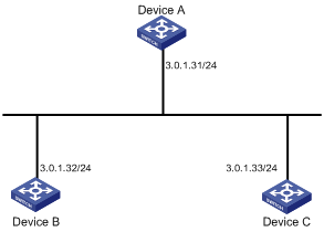
Figure 1-3 Network diagram for NTP broadcast mode configuration

Networking and Configuration Requirements
l Device C is a switch that supports to use its local clock as a reference source (for example, an S7500E switch). Its local clock is to be used as a reference source, with the stratum level of 2.
l Device A and Device D are Ethernet switches of any model listed in Applicable Product Matrix. Set Switch A and Switch D to work in the broadcast client mode and receive broadcast messages through their respective VLAN-interface 2.
Applicable Product Matrix
|
Product series |
Software version |
Hardware version |
|
S3610 Series Ethernet Switches |
Release 5301 Release 5303 |
All versions |
|
S5510 Series Ethernet Switches |
Release 5301 Release 5303 |
All versions |
|
S5500-SI Series Ethernet Switches |
Release 1207 |
All versions except S5500-20TP-SI |
|
Release 1301 |
S5500-20TP-SI |
|
|
S5500-EI Series Ethernet Switches |
Release 2102 |
All versions |
|
S7500E Series Ethernet Switches |
Release 6100 Release 6300 |
All versions |
|
S3500-EA Series Ethernet Switches |
Release 5303 |
All versions |
Configuration Procedure
1) Configure Device C
# Configure Device C to work in the broadcast server mode and send out broadcast messages through VLAN-interface 2.
<DeviceC> system-view
[DeviceC] interface Vlan-interface 2
[DeviceC-Vlan-interface2] ntp-service broadcast-server
2) Configure Device A (perform the same configuration on Device D)
# Configure Device A to work in the broadcast client mode and receive broadcast messages through VLAN-interface 2.
<DeviceA> system-view
[DeviceA] interface Vlan-interface 2
[DeviceA-Vlan-interface2] ntp-service broadcast-client
3) Configure Device D
# Configure Device D to work in the broadcast client mode and receive broadcast messages through VLAN-interface 2.
<DeviceD> system-view
[DeviceD] interface Vlan-interface 2
[DeviceD-Vlan-interface2] ntp-service broadcast-client
Complete Configuration
l Configuration on Device C
#
interface Vlan-interface2
ip address 3.0.1.13 255.255.255.0
ntp-service broadcast-server
l Configuration on Device A
#
interface Vlan-interface2
ip address 3.0.1.11 255.255.255.0
ntp-service broadcast-client
l Configuration on Device D
#
interface Vlan-interface2
ip address 3.0.1.14 255.255.255.0
ntp-service broadcast-client
Configuration Guidelines
1) The local clock of an S7500E series Ethernet switch can be configured as a reference source.
2) The local clock of an S3610/S5510/S5500-SI/S5500-EI switch cannot be configured as a reference source, unless it is synchronized by other clocks first.
Configuring NTP Multicast Mode
Network Diagram
Figure 1-4 Network diagram for NTP multicast mode configuration
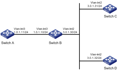
Networking and Configuration Requirements
l The local clock of Switch C is to be used as a reference source, with the stratum level of 2.
l Switch C works in the multicast server mode, and sends out multicast messages from VLAN-interface 2.
l Switch A and Switch D work in the multicast client mode and receive multicast messages through VLAN-interface 3 and VLAN-interface 2 respectively.
Applicable Product Matrix
|
Product series |
Software version |
Hardware version |
|
S3610 Series Ethernet Switches |
Release 5301 Release 5303 |
All versions |
|
S5510 Series Ethernet Switches |
Release 5301 Release 5303 |
All versions |
|
S5500-SI Series Ethernet Switches |
Release 1207 |
All versions except S5500-20TP-SI |
|
Release 1301 |
S5500-20TP-SI |
|
|
S5500-EI Series Ethernet Switches |
Release 2102 |
All versions |
|
S7500E Series Ethernet Switches |
Release 6100 Release 6300 |
All versions |
|
S3500-EA Series Ethernet Switches |
Release 5303 |
All versions |
Configuration Procedure
1) Configure Switch C.
# Specify the local clock as the reference source, with the stratum level of 2.
<SwitchC> system-view
[SwitchC] ntp-service refclock-master 2
# Configure Switch C to work in the multicast server mode and send out multicast messages through VLAN-interface 2.
[SwitchC] interface vlan-interface 2
[SwitchC-Vlan-interface2] ntp-service multicast-server
2) Configure Switch D.
# Configure Switch D to work in the multicast client mode and receive multicast messages through VLAN-interface 2.
<SwitchD> system-view
[SwitchD] interface vlan-interface 2
[SwitchD-Vlan-interface2] ntp-service multicast-client
3) Configure Switch B.
Because Switch A and Switch C are not on the same subnet, the multicast function needs to be configured on Switch B; otherwise, Switch A cannot receive the multicast messages from Switch C.
# Configure the multicast function.
<SwitchB> system-view
[SwitchB] multicast routing-enable
[SwitchB] interface vlan-interface 2
[SwitchB-Vlan-interface2] pim dm
[SwitchB-Vlan-interface2] quit
[SwitchB] vlan 3
[SwitchB-vlan3] port GigabitEthernet 1/0/1
[SwitchB-vlan3] quit
[SwitchB] interface vlan-interface 3
[SwitchB-Vlan-interface3] igmp enable
[SwitchB-Vlan-interface3] quit
[SwitchB] interface GigabitEthernet 1/0/1
[SwitchB-GigabitEthernet1/0/1] igmp-snooping static-group 224.0.1.1 vlan 3
4) Configure Switch A.
<SwitchA> system-view
[SwitchA] interface vlan-interface 3
# Configure Switch A to work in the multicast client mode and receive multicast messages through VLAN-interface 3.
[SwitchA-Vlan-interface3] ntp-service multicast-client
Complete Configuration
l Configuration on Switch A
#
interface Vlan-interface3
ntp-service multicast-client
l Configuration on Switch B
#
multicast routing-enable
#
interface Vlan-interface2
pim dm
#
interface Vlan-interface3
igmp enable
#
interface GigabitEthernet1/0/1
port access vlan 3
igmp-snooping static-group 224.0.1.1 vlan 3
l Configuration on Switch C
#
ntp-service refclock-master 2
#
interface Vlan-interface2
ntp-service multicast-server
l Configuration on Switch D
#
interface Vlan-interface2
ntp-service multicast-client
Configuration Guidelines
1) The local clock of an S7500E series Ethernet switch can be configured as a reference source.
2) The local clock of an S3610/S5510/S5500-SI/S5500-EI switch cannot be configured as a reference source, unless it is synchronized by other clocks first.
3) Switch B in this configuration example cannot be an S5500-SI series Ethernet switch, for the switch does not support the Layer 3 multicast function.
Configuring NTP Broadcast Mode with Authentication
Network Diagram
Figure 1-5 Network diagram for configuration of NTP broadcast mode with authentication

Networking and Configuration Requirements
l The local clock of Switch C is to be used as a reference source, with the stratum level of 3.
l Switch C works in the broadcast server mode, and sends out broadcast messages from VLAN-interface 2.
l Switch D works in the broadcast client mode and receives broadcast messages through VLAN-interface 2.
l NTP authentication is enabled on both Switch C and Switch D.
Applicable Product Matrix
|
Product series |
Software version |
Hardware version |
|
S3610 Series Ethernet Switches |
Release 5301 Release 5303 |
All versions |
|
S5510 Series Ethernet Switches |
Release 5301 Release 5303 |
All versions |
|
S5500-SI Series Ethernet Switches |
Release 1207 |
All versions except S5500-20TP-SI |
|
Release 1301 |
S5500-20TP-SI |
|
|
S5500-EI Series Ethernet Switches |
Release 2102 |
All versions |
|
S7500E Series Ethernet Switches |
Release 6100 Release 6300 |
All versions |
|
S3500-EA Series Ethernet Switches |
Release 5303 |
All versions |
Configuration Procedure
1) Configure Switch C.
# Specify the local clock as the reference source, with the stratum level of 3.
<SwitchC> system-view
[SwitchC] ntp-service refclock-master 3
# Configure NTP authentication.
[SwitchC] ntp-service authentication enable
[SwitchC] ntp-service authentication-keyid 88 authentication-mode md5 123456
[SwitchC] ntp-service reliable authentication-keyid 88
# Specify Switch C as an NTP broadcast server, and specify an authentication key.
[SwitchC] interface vlan-interface 2
[SwitchC-Vlan-interface2] ntp-service broadcast-server authentication-keyid 88
2) Configure Switch D.
# Configure NTP authentication.
<SwitchD> system-view
[SwitchD] ntp-service authentication enable
[SwitchD] ntp-service authentication-keyid 88 authentication-mode md5 123456
[SwitchD] ntp-service reliable authentication-keyid 88
# Configure Switch D to work in the NTP broadcast client mode.
[SwitchD] interface vlan-interface 2
[SwitchD-Vlan-interface2] ntp-service broadcast-client
Complete Configuration
l Configuration on Switch C
#
interface Vlan-interface2
ntp-service broadcast-server authentication-keyid 88
#
ntp-service authentication enable
ntp-service authentication-keyid 88 authentication-mode md5 OUM!K%F<+$[Q=^Q`MAF4<1!!
ntp-service reliable authentication-keyid 88
ntp-service refclock-master 3
#
l Configuration on Switch D
#
interface Vlan-interface2
ntp-service broadcast-client
#
ntp-service authentication enable
ntp-service authentication-keyid 88 authentication-mode md5 OUM!K%F<+$[Q=^Q`MAF4<1!!
ntp-service reliable authentication-keyid 88
#
Configuration Guidelines
1) The local clock of an S7500E series Ethernet switch can be configured as a reference source.
2) The local clock of an S3610/S5510/S5500-SI/S5500-EI switch cannot be configured as a reference source, unless it is synchronized by other clocks first.