- Table of Contents
-
- H3C Low-End and Mid-Range Ethernet Switches Configuration Examples(V1.01)
- 00-1Cover
- 01-Login Configuration Guide
- 02-VLAN Configuration Guide
- 03-GVRP Configuration Guide
- 04-Voice VLAN Configuration Guide
- 05-IP Addressing and Performance Configuration Guide
- 06-QinQ Configuration Guide
- 07-BPDU Tunnel Configuration Guide
- 08-VLAN Mapping Configuration Guide
- 09-MAC Address Table Management Configuration Guide
- 10-Link Aggregation Configuration Guide
- 11-IP Source Guard Configuration Guide
- 12-DLDP Configuration Guide
- 13-MSTP Configuration Guide
- 14-IPv4 Routing Configuration Guide
- 15-IPv6 Configuration Guide
- 16-IPv6 Routing Configuration Guide
- 17-IPv4 Multicast Configuration Guide
- 18-IPv6 Multicast Configuration Examples
- 19-802.1x Configuration Guide
- 20-AAA Configuration Guide
- 21-MAC Authentication Configuration Guide
- 22-Portal Configuration Guide
- 23-ARP Configuration Guide
- 24-DHCP Configuration Guide
- 25-ACL Configuration Guide
- 26-QoS Configuration Guide
- 27-Port Mirroring Configuration Guide
- 28-Cluster Management Configuration Guide
- 29-SNMP-RMON Configuration Guide
- 30-NTP Configuration Guide
- 31-FTP-TFTP Configuration Guide
- 32-UDP Helper Configuration Guide
- 33-Information Center Configuration Guide
- 34-DNS Configuration Guide
- 35-File System Management Configuration Guide
- 36-Remote Upgrade Configuration Guide
- 37-NQA Configuration Guide
- 38-VRRP Configuration Guide
- 39-SSH Configuration Guide
- 40-Port Security Configuration Guide
- 41-Port Isolation Configuration Guide
- 42-LLDP Configuration Guide
- 43-MCE Configuration Guide
- 44-PoE Configuration Guide
- 45-OAM Configuration Guide
- 46-Connectivity Fault Detection Configuration Guide
- 47-RRPP Configuration Guide
- 48-sFlow Configuration Guide
- 49-SSL-HTTPS Configuration Guide
- 50-PKI Configuration Guide
- 51-Track Configuration Guide
- 52-EPON-OLT Configuration Guide
- 53-Smart Link Configuration Guide
- 54-MPLS Configuration Guide
- Related Documents
-
| Title | Size | Download |
|---|---|---|
| 53-Smart Link Configuration Guide | 84.87 KB |
Table of Contents
1 Smart Link Configuration Guide
Single Smart Link Group Configuration Example
Networking and Configuration Requirements
Multiple Smart Link Groups Load Sharing Configuration Example
Networking and Configuration Requirements
Smart Link Overview
Smart Link is a feature developed to address the slow convergence issue with the Spanning Tree Protocol (STP). (For information about STP, refer to MSTP Configuration in the Access Volume.)
Smart Link is dedicated to dual-uplink networks as shown in Figure 1-1 to provide link redundancy with subsecond convergence. It allows the backup link to take over quickly when the primary link fails. In addition to fast convergence, Smart Link is easy to configure.
Single Smart Link Group Configuration Example
Network diagram
Figure 1-1 Network diagram for smart link configuration
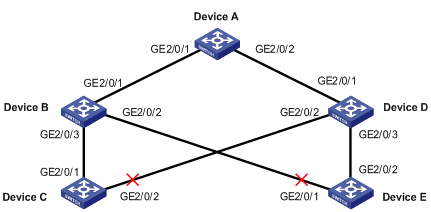
Networking and Configuration Requirements
Both Device C and Device E are dually uplinked to Device A.
Configure Smart Link on the devices for uplink backup, adopting VLAN 1 (the default) for flush update.
Applicable Product Matrix
|
Product series |
Software version |
Hardware version |
|
S7500E series Ethernet switches |
Release 6100 |
All versions |
Configuration procedure
1) Configuration on Device C
# Create smart link group 1.
<DeviceC> system-view
[DeviceC] interface GigabitEthernet 2/0/1
[DeviceC-GigabitEthernet2/0/1] undo stp enable
[DeviceC-GigabitEthernet2/0/1] quit
[DeviceC] interface GigabitEthernet 2/0/2
[DeviceC-GigabitEthernet2/0/2] undo stp enable
[DeviceC-GigabitEthernet2/0/2] quit
[DeviceC] smart-link group 1
# Configure all VLANs mapped to MSTIs 0 through 31 as the protected VLANs (The MSTIs range from 0 to 31).
[DeviceC-smlk-group1] protected-vlan reference-instance 0 to 31
# Configure GigabitEthernet 2/0/1 as the master port and GigabitEthernet 2/0/2 as the slave port.
[DeviceC-smlk-group1] port GigabitEthernet2/0/1 master
[DeviceC-smlk-group1] port GigabitEthernet2/0/2 slave
# Configure VLAN 1 as the transmit control VLAN.
[DeviceC-smlk-group1] flush enable
2) Configuration on Device E
# Create smart link group 1.
<DeviceE> system-view
[DeviceE] interface GigabitEthernet 2/0/1
[DeviceE-GigabitEthernet2/0/1] undo stp enable
[DeviceE-GigabitEthernet2/0/1] quit
[DeviceE] interface GigabitEthernet 2/0/2
[DeviceE-GigabitEthernet2/0/2] undo stp enable
[DeviceE-GigabitEthernet2/0/2] quit
[DeviceE] smart-link group 1
# Configure all VLANs mapped to MSTIs 0 through 31 as the protected VLANs (The MSTIs range from 0 to 31).
[DeviceC-smlk-group1] protected-vlan reference-instance 0 to 31
# Configure GigabitEthernet 2/0/2 as the master port and GigabitEthernet 2/0/1 as the slave port.
[DeviceE-smlk-group1] port GigabitEthernet2/0/2 master
[DeviceE-smlk-group1] port GigabitEthernet2/0/1 slave
# Configure VLAN 1 as the transmit control VLAN.
[DeviceE-smlk-group1] flush enable
3) Configuration on Device B
# Configure VLAN 1 as the receive control VLAN for GigabitEthernet 2/0/1, GigabitEthernet 2/0/2, and GigabitEthernet 2/0/3.
<DeviceB> system-view
[DeviceB] interface GigabitEthernet 2/0/1
[DeviceB-GigabitEthernet2/0/1] smart-link flush enable
[DeviceB-GigabitEthernet2/0/1] quit
[DeviceB] interface GigabitEthernet 2/0/2
[DeviceB-GigabitEthernet2/0/2] smart-link flush enable
[DeviceB-GigabitEthernet2/0/2] quit
[DeviceB] interface GigabitEthernet 2/0/3
[DeviceB-GigabitEthernet2/0/3] smart-link flush enable
4) Configuration on Device D
# Configure VLAN 1 as the receive control VLAN for GigabitEthernet 2/0/1, GigabitEthernet 2/0/2, and GigabitEthernet 2/0/3.
<DeviceD> system-view
[DeviceD] interface GigabitEthernet 2/0/1
[DeviceD-GigabitEthernet2/0/1] smart-link flush enable
[DeviceD-GigabitEthernet2/0/1] quit
[DeviceD] interface GigabitEthernet 2/0/2
[DeviceD-GigabitEthernet2/0/2] smart-link flush enable
[DeviceD-GigabitEthernet2/0/2] quit
[DeviceD] interface GigabitEthernet 2/0/3
[DeviceD-GigabitEthernet2/0/3] smart-link flush enable
5) Configuration on Device A
# Configure VLAN 1 as the receive control VLAN for GigabitEthernet 2/0/1, GigabitEthernet 2/0/2, and GigabitEthernet 2/0/3.
<DeviceA> system-view
[DeviceA] interface GigabitEthernet 2/0/1
[DeviceA-GigabitEthernet2/0/1] smart-link flush enable
[DeviceA-GigabitEthernet2/0/1] quit
[DeviceA] interface GigabitEthernet 2/0/2
[DeviceA-GigabitEthernet2/0/2] smart-link flush enable
After completing the configuration, you can use the display command to verify the smart link configuration and view flush message statistics.
Complete Configuration
l Configuration on Device A
#
interface GigabitEthernet2/0/1
smart-link flush enable control-vlan 1
#
interface GigabitEthernet2/0/2
smart-link flush enable control-vlan 1
#
l Configuration on Device B
#
interface GigabitEthernet2/0/1
smart-link flush enable control-vlan 1
#
interface GigabitEthernet2/0/2
smart-link flush enable control-vlan 1
#
interface GigabitEthernet2/0/3
smart-link flush enable control-vlan 1
#
l Configuration on Device C
#
smart-link group 1
protected-vlan reference-instance 0 to 31
#
interface GigabitEthernet2/0/1
undo stp enable
port smart-link group 1 master
#
interface GigabitEthernet2/0/2
undo stp enable
port smart-link group 1 slave
#
l Configuration on Device D
#
interface GigabitEthernet2/0/1
smart-link flush enable control-vlan 1
#
interface GigabitEthernet2/0/2
smart-link flush enable control-vlan 1
#
interface GigabitEthernet2/0/3
smart-link flush enable control-vlan 1
#
l Configuration on Device E
#
smart-link group 1
protected-vlan reference-instance 0 to 31
#
interface GigabitEthernet2/0/1
undo stp enable
port smart-link group 1 slave
#
interface GigabitEthernet2/0/2
undo stp enable
port smart-link group 1 master
#
Configuration Guidelines
l Before configuring a port as a smart link group member, shut down the port to prevent loops. You can bring up the port only after completing the smart link group configuration.
l Disable STP and RRPP on the ports you want to add to the smart link group, and make sure that the ports are not member ports of any aggregation group or service loopback group.
l The protected VLANs configured for a smart link group must be different from those configured for any other smart link group.
l Make sure that the configured control VLANs are existing VLANs, and you must assign the smart link group member ports to the control VLANs.
l Do not remove the control VLANs. Otherwise, flush messages cannot be sent properly.
l Make sure that the receive control VLAN is the same as the transmit control VLAN configured on the Smart Link device. If they are not the same, the associated device will forward the received flush messages directly without any processing.
Multiple Smart Link Groups Load Sharing Configuration Example
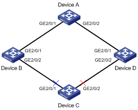
Network diagram
Figure 1-2 Network diagram for multi-instance load sharing configuration
Networking and Configuration Requirements
l The traffic of VLAN 1 through VLAN 200 on Device C are dually uplinked to Device A by Device B and Device D. Implement load sharing to uplink the traffic of VLAN 1 through VLAN 100 and the traffic of VLAN 101 through VLAN 200 over different links to Device A.
l Implement dual link backup on Device C: the traffic of VLANs 1 through 100 (mapped to MSTI 0) is uplinked to Device A by Device B; the traffic of VLANs 101 through 200 (mapped to MSTI 2) is uplinked to Device A by Device D. Smart link group 1 references MSTI 0, and smart link group 2 references MSTI 2.
l The control VLAN of smart link group 1 is VLAN 10 and that of smart link group 2 is VLAN 101.
Applicable Product Matrix
|
Product series |
Software version |
Hardware version |
|
S7500E series Ethernet switches |
Release 6100 |
All versions |
Configuration procedure
1) Configuration on Device C
# Create VLANs and configure VLAN-to-MSTI mappings.
<DeviceC> system-view
[DeviceC] vlan 1 to 200
[DeviceC] stp region-configuration
[DeviceC-mst-region] instance 0 vlan 1 to 100
[DeviceC-mst-region] instance 2 vlan 101 to 200
[DeviceC-mst-region] active region-configuration
[DeviceC-mst-region] quit
# Disable STP on the ports, configure the ports as trunk ports, and configure the ports to allow packets from VLAN 1 through 200 to pass through.
[DeviceC] interface GigabitEthernet 2/0/1
[DeviceC-GigabitEthernet2/0/1] undo stp enable
[DeviceC-GigabitEthernet2/0/1] port link-type trunk
[DeviceC-GigabitEthernet2/0/1] port trunk permit vlan 1 to 200
[DeviceC-GigabitEthernet2/0/1] quit
[DeviceC-GigabitEthernet2/0/1] interface GigabitEthernet 2/0/2
[DeviceC-GigabitEthernet2/0/2] undo stp enable
[DeviceC-GigabitEthernet2/0/2] port link-type trunk
[DeviceC-GigabitEthernet2/0/2] port trunk permit vlan 1 to 200
[DeviceC-GigabitEthernet2/0/2] quit
# Create smart link group 1.
[DeviceC] smart-link group 1
# Configure protected VLANs for smart link group 1.
[DeviceC-smlk-group1] protected-vlan reference-instance 0
# Configure GigabitEthernet 2/0/1 as the master port and GigabitEthernet 2/0/2 as the slave port.
[DeviceC-smlk-group1] port GigabitEthernet 2/0/1 master
[DeviceC-smlk-group1] port GigabitEthernet 2/0/2 slave
# Enable role preemption.
[DeviceC-smlk-group1] preemption mode role
# Configure VLAN 10 as the transmit control VLAN of smart link group 1.
[DeviceC-smlk-group-1] flush enable control-vlan 10
[DeviceC-smlk-group-1] quit
# Create smart link group 2.
[DeviceC] smart-link group 2
# Configure protected VLANs for smart link group 2.
[DeviceC-smlk-group2] protected-vlan reference-instance 2
# Configure GigabitEthernet 2/0/1 as the slave port and GigabitEthernet 2/0/2 as the master port.
[DeviceC-smlk-group2] port GigabitEthernet 2/0/1 slave
[DeviceC-smlk-group2] port GigabitEthernet 2/0/2 master
# Enable role preemption.
[DeviceC-smlk-group2] preemption mode role
# Configure VLAN 101 as the transmit control VLAN of smart link group 2.
[DeviceC-smlk-group2] flush enable control-vlan 101
2) Configuration on Device B
# Configure VLAN 10 and VLAN 101 as the receive control VLANs of GigabitEthernet 2/0/1 and GigabitEthernet 2/0/2.
<DeviceB> system-view
[DeviceB] vlan 1 to 200
[DeviceB] interface GigabitEthernet 2/0/1
[DeviceB-GigabitEthernet2/0/1] port link-type trunk
[DeviceB-GigabitEthernet2/0/1] port trunk permit vlan 1 to 200
[DeviceB-GigabitEthernet2/0/1] smart-link flush enable control-vlan 10 101
[DeviceB-GigabitEthernet2/0/1] quit
[DeviceB] interface GigabitEthernet 2/0/2
[DeviceB-GigabitEthernet2/0/2] port link-type trunk
[DeviceB-GigabitEthernet2/0/2] port trunk permit vlan 1 to 200
[DeviceB-GigabitEthernet2/0/2] smart-link flush enable control-vlan 10 101
3) Configuration on Device D
# Configure VLAN 10 and VLAN 101 as the receive control VLANs of GigabitEthernet 2/0/1 and GigabitEthernet 2/0/2.
<DeviceD> system-view
[DeviceD] vlan 1 to 200
[DeviceD] interface GigabitEthernet 2/0/1
[DeviceD-GigabitEthernet2/0/1] port link-type trunk
[DeviceD-GigabitEthernet2/0/1] port trunk permit vlan 1 to 200
[DeviceD-GigabitEthernet2/0/1] smart-link flush enable control-vlan 10 101
[DeviceD-GigabitEthernet2/0/1] quit
[DeviceD]interface GigabitEthernet 2/0/2
[DeviceD-GigabitEthernet2/0/2] port link-type trunk
[DeviceD-GigabitEthernet2/0/2] port trunk permit vlan 1 to 200
[DeviceD-GigabitEthernet2/0/2] smart-link flush enable control-vlan 10 101
4) Configuration on Device A
# Configure VLAN 10 and VLAN 101 as the receive control VLANs of GigabitEthernet 2/0/1 and GigabitEthernet 2/0/2.
<DeviceA> system-view
[DeviceA] vlan 1 to 200
[DeviceA] interface GigabitEthernet 2/0/1
[DeviceA-GigabitEthernet2/0/1] port link-type trunk
[DeviceA-GigabitEthernet2/0/1] port trunk permit vlan 1 to 200
[DeviceA-GigabitEthernet2/0/1] smart-link flush enable control-vlan 10 101
[DeviceA-GigabitEthernet2/0/1] quit
[DeviceA] interface GigabitEthernet 2/0/2
[DeviceA-GigabitEthernet2/0/2] port link-type trunk
[DeviceA-GigabitEthernet2/0/2] port trunk permit vlan 1 to 200
[DeviceA-GigabitEthernet2/0/2] smart-link flush enable control-vlan 10 101
After completing the configuration, you can use the display command to verify the smart link configuration and view flush message statistics.
Complete Configuration
l Configuration on Device A
#
vlan 1
#
vlan 2 to 200
#
interface GigabitEthernet2/0/1
port link-type trunk
port trunk permit vlan 1 to 200
smart-link flush enable control-vlan 10 101
#
interface GigabitEthernet2/0/2
port link-type trunk
port trunk permit vlan 1 to 200
smart-link flush enable control-vlan 10 101
#
l Configuration on Device B
#
vlan 1
#
vlan 2 to 200
#
interface GigabitEthernet2/0/1
port link-type trunk
port trunk permit vlan 1 to 200
smart-link flush enable control-vlan 10 101
#
interface GigabitEthernet2/0/2
port link-type trunk
port trunk permit vlan 1 to 200
smart-link flush enable control-vlan 10 101
#
l Configuration on Device C
vlan 1
#
vlan 2 to 200
#
stp region-configuration
instance 2 vlan 101 to 200
active region-configuration
#
smart-link group 1
preemption mode role
protected-vlan reference-instance 0
flush enable control-vlan 10
smart-link group 2
preemption mode role
protected-vlan reference-instance 2
flush enable control-vlan 101
#
interface GigabitEthernet2/0/1
port link-type trunk
port trunk permit vlan 1 to 200
undo stp enable
port smart-link group 1 master
port smart-link group 2 slave
#
interface GigabitEthernet2/0/2
port link-type trunk
port trunk permit vlan 1 to 200
undo stp enable
port smart-link group 1 slave
port smart-link group 2 master
#
l Configuration on Device D
#
vlan 1
#
vlan 2 to 200
#
interface GigabitEthernet2/0/1
port link-type trunk
port trunk permit vlan 1 to 200
smart-link flush enable control-vlan 10 101
#
interface GigabitEthernet2/0/2
port link-type trunk
port trunk permit vlan 1 to 200
smart-link flush enable control-vlan 10 101
#
Configuration Guidelines
Refer to 1332456 Configuration Guidelines.