- Table of Contents
-
- H3C Low-End and Mid-Range Ethernet Switches Configuration Examples(V1.01)
- 00-1Cover
- 01-Login Configuration Guide
- 02-VLAN Configuration Guide
- 03-GVRP Configuration Guide
- 04-Voice VLAN Configuration Guide
- 05-IP Addressing and Performance Configuration Guide
- 06-QinQ Configuration Guide
- 07-BPDU Tunnel Configuration Guide
- 08-VLAN Mapping Configuration Guide
- 09-MAC Address Table Management Configuration Guide
- 10-Link Aggregation Configuration Guide
- 11-IP Source Guard Configuration Guide
- 12-DLDP Configuration Guide
- 13-MSTP Configuration Guide
- 14-IPv4 Routing Configuration Guide
- 15-IPv6 Configuration Guide
- 16-IPv6 Routing Configuration Guide
- 17-IPv4 Multicast Configuration Guide
- 18-IPv6 Multicast Configuration Examples
- 19-802.1x Configuration Guide
- 20-AAA Configuration Guide
- 21-MAC Authentication Configuration Guide
- 22-Portal Configuration Guide
- 23-ARP Configuration Guide
- 24-DHCP Configuration Guide
- 25-ACL Configuration Guide
- 26-QoS Configuration Guide
- 27-Port Mirroring Configuration Guide
- 28-Cluster Management Configuration Guide
- 29-SNMP-RMON Configuration Guide
- 30-NTP Configuration Guide
- 31-FTP-TFTP Configuration Guide
- 32-UDP Helper Configuration Guide
- 33-Information Center Configuration Guide
- 34-DNS Configuration Guide
- 35-File System Management Configuration Guide
- 36-Remote Upgrade Configuration Guide
- 37-NQA Configuration Guide
- 38-VRRP Configuration Guide
- 39-SSH Configuration Guide
- 40-Port Security Configuration Guide
- 41-Port Isolation Configuration Guide
- 42-LLDP Configuration Guide
- 43-MCE Configuration Guide
- 44-PoE Configuration Guide
- 45-OAM Configuration Guide
- 46-Connectivity Fault Detection Configuration Guide
- 47-RRPP Configuration Guide
- 48-sFlow Configuration Guide
- 49-SSL-HTTPS Configuration Guide
- 50-PKI Configuration Guide
- 51-Track Configuration Guide
- 52-EPON-OLT Configuration Guide
- 53-Smart Link Configuration Guide
- 54-MPLS Configuration Guide
- Related Documents
-
| Title | Size | Download |
|---|---|---|
| 52-EPON-OLT Configuration Guide | 206 KB |
Table of Contents
1 EPON-OLT Configuration Guide
Configuring OLT Port Isolation
ONU Remote Management Configuration Examples
Configuring Binding an ONU Port to an ONU
Configuring Multicast (in IGMP Snooping Mode)
Configuring Multicast (in Multicast Control Mode)
ONU Update Configuration Example
UNI Port Configuration Examples
Configuring UNI Priority Remarking
OLT Configuration Examples
Configuring OLT Port Isolation
Network diagram
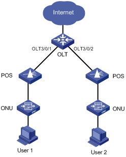
Figure 1-1 Network diagram for OLT port isolation
Networking and Configuration Requirements
l An OLT device is connected to the Internet through the uplink port.
l Configure port isolation between OLT 3/0/1 and OLT 3/0/2 so that the users under OLT 3/0/1 and those under OLT 3/0/2 can access the Internet but cannot communicate with each other at Layer 2.
Applicable Product Matrix
|
Product series |
Software version |
Hardware version |
|
S7500E Series Ethernet Switches |
Release 6300 |
All versions |
Configuration procedure
# Add OLT 3/0/1 and OLT 3/0/2 to an isolation group.
<Sysname> system-view
[Sysname] interface olt3/0/1
[Sysname-Olt3/0/1] port-isolate enable
[Sysname-Olt3/0/1] quit
[Sysname] interface olt3/0/2
[Sysname-Olt3/0/2] port-isolate enable
[Sysname-Olt3/0/2] quit
# Display the isolation group information.
<Sysname> display port-isolate group
Port-isolate group information:
Uplink port support: NO
Group ID: 1
olt3/0/1 olt3/0/2
Complete configuration
#
interface Olt3/0/1
port-isolate enable
#
interface Olt3/0/2
port-isolate enable
Configuration guidelines
None
Configuring Fiber Backup
Network diagram
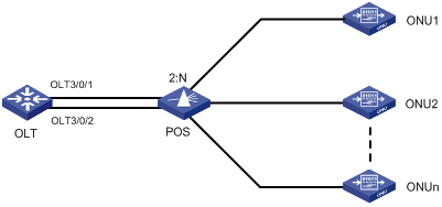
Figure 1-2 Network diagram for fiber backup group configuration
Networking and Configuration Requirements
l Add two OLT ports of the same EPON board to a fiber backup group one after the other.
l Perform a manual switchover between the two OLT ports. When the master port is shut down, the slave port becomes the new master port.
Applicable Product Matrix
|
Product series |
Software version |
Hardware version |
|
S7500E Series Ethernet Switches |
Release 6300 |
All versions |
Configuration procedure
# Create fiber backup group 1.
<Sysname> system-view
[Sysname] ftth
[Sysname-ftth] fiber-backup group 1
Create group 1 successfully.
# Add port OLT 3/0/1 and then OLT 3/0/2 to fiber backup group 1. Thus, OLT 3/0/1 works as the master port and OLT 3/0/2 the slave port.
[Sysname-fiber-group1] group member olt3/0/1
[Sysname-fiber-group1] group member olt3/0/2
[Sysname-fiber-group1] display fiber-backup group 1
fiber backup group 1 information:
Member Role State
-----------------------------------------
Olt3/0/1 MASTER ACTIVE
Olt3/0/2 SLAVE READY
# Perform a master/slave switchover between OLT 3/0/1 and OLT 3/0/2.
[Sysname-fiber-group1] port switch-over
[Sysname-fiber-group1] display fiber-backup group 1
fiber backup group 1 information:
Member Role State
-----------------------------------------
Olt3/0/2 MASTER ACTIVE
Olt3/0/1 SLAVE READY
# Shut down OLT 3/0/2. You can see that OLT 3/0/1 becomes the new master port.
[Sysname-fiber-group1] quit
[Sysname] interface olt3/0/2
[Sysname-Olt3/0/2] shutdown
[Sysname-Olt3/0/2] display fiber-backup group 1
fiber backup group 1 information:
Member Role State
-----------------------------------------
Olt3/0/1 MASTER ACTIVE
Olt3/0/2 SLAVE DOWN
Complete configuration
#
interface Olt3/0/1
port-isolate enable
#
interface Olt3/0/2
port-isolate enable
Configuration guidelines
None
Configuring IP Source Guard
Network diagram
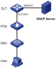
Figure 1-3 Network diagram for IP Source Guard configuration
Networking and Configuration Requirements
l An OLT device is connected to the DHCP server through Ethernet 2/0/1 and connected to an ONU through OLT 3/0/1. UNI 1 of the ONU is connected to a user device.
l Enable DHCP snooping on the OLT device.
l Bind port ONU 3/0/1:1 to the ONU.
l The user device, with the MAC address 00-01-02-03-04-06, obtains an IP address through the DHCP server. The DHCP snooping entry for the user device is generated on the OLT device.
l Enable IP Source Guard on OLT 3/0/1 to protect the server against attacks launched by clients using fake source IP addresses.
This example shows only the OLT configuration. For DHCP server configuration, refer to the DHCP Configuration Guide.
Applicable Product Matrix
|
Product series |
Software version |
Hardware version |
|
S7500E Series Ethernet Switches |
Release 6300 |
All versions |
Configuration procedure
1) Configure the OLT device.
# Enable DHCP snooping.
<Sysname> system-view
[Sysname] dhcp-snooping
# Configure Ethernet 2/0/1, which is connected to the DHCP server, as a trust port.
[Sysname] interface ethernet2/0/1
[Sysname-Ethernet2/0/1] dhcp-snooping trust
[Sysname-Ethernet2/0/1] quit
# Enable IP Source Guard on OLT 3/0/1.
[Sysname-Olt3/0/1] ip check source ip-address mac-address
[Sysname-Olt3/0/1] quit
# Create an ONU port ONU 3/0/1:1 and bind it with the ONU.
[Sysname] interface olt 3/0/1
[Sysname-Olt3/0/1] using onu 1
[Sysname-Olt3/0/1] quit
[Sysname] interface onu3/0/1:1
[Sysname-Onu3/0/1:1] bind onuid 000f-e200-0001
2) Verify the configuration.
# Display the dynamic DHCP snooping entry obtained by OLT 3/0/1.
<Sysname> display ip check source interface olt 3/0/1
The Following User address bind have been configured:
Mac IP Port Status
0001-0203-0406 192.168.0.1 Olt3/0/1 Dynamic
-------------1 bind entries queried, 1 listed------------
# Display the existing dynamic DHCP snooping entry to check whether it is the same as the one obtained by OLT 3/0/1.
<Sysname> display dhcp-snooping
DHCP Snooping is enabled.
The client binding table for all untrusted ports.
Type : D--Dynamic , S--Static
Type IP Address MAC Address Lease VLAN Interface
==== =============== ============== ============ ==== =================
D 192.168.0.1 0001-0203-0406 86335 1 Olt3/0/1
The display shows that, after IP Source Guard is enabled on OLT 3/0/1, the port obtains the dynamic entry generated by DHCP snooping.
Complete configuration
#
dhcp-snooping
#
interface GigabitEthernet2/0/1
dhcp-snooping trust
#
interface Olt3/0/1
using onu 1
ip check source ip-address mac-address
#
interface Onu3/0/1:1
bind onuid 000f-e200-0001
Configuration guidelines
None
ONU Remote Management Configuration Examples
Configuring Binding an ONU Port to an ONU
Network diagram
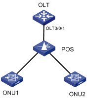
Figure 1-4 Network diagram for ONU port-to-ONU binding configuration
Networking and Configuration Requirements
Bind ONU 3/0/1:1 to ONU 1, whose MAC address is 000f-e200-0031, and ONU 3/0/1:2 to ONU 2, whose MAC address is 000f-e200-3749.
Applicable Product Matrix
|
Product series |
Software version |
Hardware version |
|
S7500E Series Ethernet Switches |
Release 6300 |
All versions |
Configuration procedure
# Configure the OUI and extended OAM version number list.
<Sysname> system-view
System View: return to User View with Ctrl+Z.
[Sysname] ftth
[Sysname-ftth] quit
# Create ONU ports ONU 3/0/1:1 and ONU 3/0/1:2. Bind ONU 3/0/1:1 to the ONU 1 and ONU 3/0/1:2 to ONU 2.
[Sysname] interface olt 3/0/1
[Sysname-Olt3/0/1] using onu 1 to 2
[Sysname-Olt3/0/1] quit
[Sysname] interface onu 3/0/1:1
[Sysname-Onu3/0/1:1] bind onuid 000f-e200-0031
[Sysname-Onu3/0/1:1] quit
[Sysname] interface onu 3/0/1:2
[Sysname-Onu3/0/1:2] bind onuid 000f-e200-3749
# When the two ONUs are up, display the binding information of the ONUs.
<Sysname> display onuinfo interface Olt 4/0/1
ONU Mac Address LLID Dist(M) Port Board/Ver Sft/Epm State Aging
000f-e200-0031 1 <50 Onu4/0/1:1 ET704-A-L/B 110/100 Up N/A
000f-e200-3749 2 <50 Onu4/0/1:2 ET704-A-L/B 110/100 Up N/A
--- 2 entries found ---
Complete configuration
#
ftth
epon-parameter ouilist oui 000fe2 oam-version 2 slot 3
#
interface Olt3/0/1
using onu 1 to 2
#
interface Onu3/0/1:1
bind onuid 000f-e200-0031
#
interface Onu3/0/1:2
bind onuid 000f-e200-3749
Configuration guidelines
l An ONU port can only be bound with one ONU MAC address. Conversely, an ONU MAC address can only be bound to one ONU port under one OLT port.
l In fiber backup, an ONU can be bound with two ONU ports under two OLT ports acting as backups for each other.
Configuring ONU RSTP
Network diagram
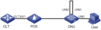
Figure 1-5 Network diagram for ONU RSTP configuration
Networking and Configuration Requirements
l A user PC is attached to UNI 1. If UNI 2 and UNI 3 are interconnected by mistake while RSTP is disabled on the ONU, broadcast storm will occur between UNI 2 and UNI 3 when the user pings an IP address for which no ARP entry exists on the PC.
l Enabling RSTP on the ONU can suppress such a problem.
Applicable Product Matrix
|
Product series |
Software version |
Hardware version |
|
S7500E Series Ethernet Switches |
Release 6300 |
All versions |
Configuration procedure
# Enable RSTP on the ONU to suppress the broadcast storm between UNI 2 and UNI 3.
<Sysname> system-view
[Sysname] interface onu 3/0/1:1
[Sysname-Onu3/0/1:1] onu-protocol stp enable
Complete configuration
#
interface Onu3/0/1:1
onu-protocol stp enable
Configuration guidelines
When STP is enabled globally on the S7500E switch, you should enable STP on all ONUs. Additionally, configure STP correctly to ensure that no ONU can be selected as the STP root bridge; otherwise, anomaly may occur on the network.
Configuring Multicast (in IGMP Snooping Mode)
Network diagram
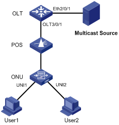
Figure 1-6 Network diagram for multicast configuration (in IGMP snooping mode)
Networking and Configuration Requirements
l Connect Ethernet 2/0/1 of the switch with a multicast source, and connect port OLT 3/0/1 of the OLT with an ONU, which is bound to ONU 3/0/1:1, through an optical splitter. Attach two hosts, User 1 and User 2, to ports UNI 1 and UNI 2 respectively.
l It is required that User 1 has access to channels from 225.1.2.1 to 225.1.2.255, and User 2 has access to channels from 225.1.3.1 to 225.1.3.255.
Applicable Product Matrix
|
Product series |
Software version |
Hardware version |
|
S7500E Series Ethernet Switches |
Release 6300 |
All versions |
Configuration procedure
# Map the multicast addresses to multicast VLANs.
<Sysname> system-view
[Sysname] ftth
[Sysname-ftth] multicast vlan-id 1002 dest-ip 225.1.2.1 to 225.1.2.255
[Sysname-ftth] multicast vlan-id 1003 dest-ip 225.1.3.1 to 225.1.3.255
[Sysname-ftth] quit
# Enable IGMP snooping globally.
[Sysname] igmp-snooping
[Sysname-igmp-snooping] quit
# Enable IGMP snooping in VLAN 1002 and VLAN 1003.
[Sysname] vlan 1002
[Sysname-vlan1002] igmp-snooping enable
[Sysname-vlan1002] quit
[Sysname] vlan 1003
[Sysname-vlan1003] igmp-snooping enable
[Sysname-vlan1003] quit
# Configure the multicast mode of the ONU as IGMP snooping.
[Sysname-Onu3/0/1:1] multicast-mode igmp-snooping
# Assign UNI 1 to multicast VLAN 1002 and UNI 2 to multicast VLAN 1003, and configure the ONU as a Trunk port (to allow the packets of all the VLANs to pass through the port).
[Sysname-Onu3/0/1:1] uni 1 multicast vlan 1002
[Sysname-Onu3/0/1:1] uni 2 multicast vlan 1003
[Sysname-Onu3/0/1:1] port link-type trunk
# Configure UNI 1 and UNI 2 to remove the multicast VLAN tags from downlink multicast packets.
[Sysname-Onu3/0/1:1] uni 1 multicast-strip-tag enable
[Sysname-Onu3/0/1:1] uni 2 multicast-strip-tag enable
[Sysname-Onu3/0/1:1] quit
# Configure the link type of OLT 3/0/1 as hybrid, allow the packets of VLAN 1002 and VLAN 1003 to pass through OLT 3/0/1, and add tags to the VLAN 1002 and VLAN 1003 packets sent by OLT 3/0/1.
[Sysname] interface olt 3/0/1
[Sysname-Olt3/0/1] port link-type hybrid
[Sysname-Olt3/0/1] port hybrid vlan 1002 1003 tagged
# Configure Ethernet 2/0/1 as a Trunk port, and permit the packets of VLAN 1002 and VLAN 1003 to pass.
[Sysname] interface Ethernet2/0/1
[Sysname-Ethernet2/0/1] port link-type trunk
[Sysname-Ethernet2/0/1] port trunk permit vlan 1002 1003
Complete configuration
#
igmp-snooping
#
vlan 1002
igmp-snooping enable
#
vlan 1003
igmp-snooping enable
# #
ftth
multicast vlan-id 1002 dest-ip 225.1.2.1 to 225.1.2.255
multicast vlan-id 1003 dest-ip 225.1.3.1 to 225.1.3.255
#
interface GigabitEthernet2/0/1
port link-type trunk
port trunk permit vlan 1 1002 to 1003
#
interface Olt3/0/1
using onu 1
port link-type hybrid
port hybrid vlan 1 1002 to 1003 tagged
#
interface Onu3/0/1:1
uni 1 multicast vlan 1002
uni 1 multicast-strip-tag enable
uni 2 multicast vlan 1003
uni 2 multicast-strip-tag enable
port link-type trunk
Configuration guidelines
A multicast IP address can belong to only one multicast VLAN.
Configuring Multicast (in Multicast Control Mode)
Network diagram
Figure 1-7 Network diagram for multicast configuration (in multicast control mode)
Networking and Configuration Requirements
Connect Ethernet 2/0/1 of the switch with a multicast source, and connect port OLT 3/0/1 of the OLT with an ONU, which is bound to ONU 3/0/1:1, through an optical splitter. Attach two hosts, User 1 and User 2, to ports UNI 1 and UNI 2 respectively.
It is required that User 1 and User 2 have different access rights to Channel 1 (225.1.1.1) and Channel 1 (225.1.2.1):
l User 1 has full access to Channel 1 and 60-second preview access to Channel 2.
l User 2 has access to Channel 2 only.
Applicable Product Matrix
|
Product series |
Software version |
Hardware version |
|
S7500E Series Ethernet Switches |
Release 6300 |
All versions |
Configuration procedure
# Map the multicast addresses to multicast VLANs.
<Sysname> system-view
[Sysname] ftth
[Sysname-ftth] multicast vlan-id 1002 dest-ip 225.1.1.1
[Sysname-ftth] multicast vlan-id 1003 dest-ip 225.1.2.1
[Sysname-ftth] quit
# Enable IGMP snooping globally.
[Sysname] igmp-snooping
[Sysname-igmp-snooping] quit
# Enable IGMP snooping in VLAN 1002 and VLAN 1003.
[Sysname] vlan 1002
[Sysname-vlan1002] igmp-snooping enable
[Sysname-vlan1002] vlan 1003
[Sysname-vlan1003] igmp-snooping enable
[Sysname-vlan1003] quit
# Configure the multicast mode of the ONU as the multicast control mode.
[Sysname-Onu3/0/1:1] multicast-mode multicast-control
# Configure UNI 1 to allow the user attached to it to access Channel 1 and to preview Channel 2 for only 60 seconds, and configure the port to remove the multicast VLAN tags from downlink multicast packets.
[Sysname-Onu3/0/1:1] uni 1 multicast-control multicast-address 225.1.1.1 rule permit
[Sysname-Onu3/0/1:1] uni 1 multicast-control multicast-address 225.1.2.1 rule preview time-slice 1
[Sysname-Onu3/0/1:1] uni 1 multicast-strip-tag enable
# Configure UNI 2 to allow the user attached to it to access Channel 2 only, and configure the port to remove the multicast VLAN tags from downlink multicast packets.
[Sysname-Onu3/0/1:1] uni 2 multicast-control multicast-address 225.1.1.1 rule deny
[Sysname-Onu3/0/1:1] uni 2 multicast-control multicast-address 225.1.2.1 rule permit
[Sysname-Onu3/0/1:1] uni 2 multicast-strip-tag enable
# Configure the ONU port as a Trunk port (to allow the packets of all the VLANs to pass through the port).
[Sysname-Onu3/0/1:1] port link-type trunk
# Configure the link type of OLT 3/0/1 as hybrid, allow the packets of VLAN 1002 and VLAN 1003 to pass through OLT 3/0/1, and add tags to the VLAN 1002 and VLAN 1003 packets sent by OLT 3/0/1.
[Sysname] interface olt 3/0/1
[Sysname-Olt3/0/1] port link-type hybrid
[Sysname-Olt3/0/1] port hybrid vlan 1002 1003 tagged
# Configure Ethernet 2/0/1 as a Trunk port, and permit the packets of VLAN 1002 and VLAN 1003 to pass through the port.
[Sysname] interface Ethernet2/0/1
[Sysname-Ethernet2/0/1] port link-type trunk
[Sysname-Ethernet2/0/1] port trunk permit vlan 1002 1003
Complete configuration
#
igmp-snooping
#
vlan 1002
igmp-snooping enable
#
vlan 1003
igmp-snooping enable
#
ftth
multicast vlan-id 1002 dest-ip 225.1.1.1
multicast vlan-id 1003 dest-ip 225.1.2.1
#
interface GigabitEthernet2/0/1
port link-type trunk
port trunk permit vlan 1 1002 to 1003
#
interface Olt3/0/1
using onu 1
port link-type hybrid
port hybrid vlan 1 1002 to 1003 tagged
#
interface Onu3/0/1:1
multicast-mode multicast-control
uni 1 multicast-strip-tag enable
uni 2 multicast-strip-tag enable
uni 1 multicast-control multicast-address 225.1.1.1 rule permit
uni 1 multicast-control multicast-address 225.1.2.1 rule preview time-slice 1
uni 2 multicast-control multicast-address 225.1.1.1 rule deny
uni 2 multicast-control multicast-address 225.1.2.1 rule permit
port link-type trunk
Configuration guidelines
A multicast IP address can belong to only one multicast VLAN.
ONU Update Configuration Example
Network diagram
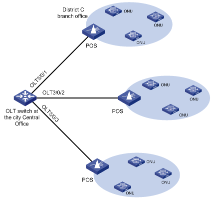
Figure 1-8 Network diagram for ONU update
Networking and Configuration Requirements
l An S7500E switch at the city TV & broadcasting central office (CO) has 12 OLT ports connected to 150 type-A ONUs.
l The type-A ONU vendor recently released an enhanced software version 110 for type-A ONUs. This version solves some software bugs found in the previous version 109 and provides some new functions.
l The city office wants to update all the ONUs. District C branch office (connected to OLT 3/0/1) has 5 type-A ONUs under it. The network administrator believes version 109 can meet the current requirements and has worked normally and thus continues to use version 109 in the network. However, to prepare for upgrading to version 110 in the future, the network administrator asks to use version 110 on a trial basis in the branch office building (ONU 3/0/1:1 is bound with type-A ONUs for FTTB access to the building).
Applicable Product Matrix
|
Product series |
Software version |
Hardware version |
|
S7500E Series Ethernet Switches |
Release 6300 |
All versions |
Configuration procedure
# Upload update files a110.app and a109.app to the master SRPU and slave SRPU of the switch. For the detailed procedure, see the parts discussing software maintenance in H3C S7500E Series Ethernet Switches Installation Manual.
# You can update the software version of your ONU device in port view (OLT port view, ONU port view) and FTTH view. The configurations made in port views take precedence over those made in FTTH view; the configurations made in the two port views have the same priorities, but the latest port-level configurations overwrite the previous ones. According to the network requirements, update the ONU software version as follows:
l In the port view of OLT 3/0/1, update all type-A ONUs under OLT 3/0/1 to version 109.
l In the port view of ONU 3/0/1:1, update all type-A ONUs under ONU 3/0/1:1 to version 110.
l In FTTH view, update all ONUs under the twelve OLTs of the S7500E switch to version 110. Because the configurations made in OLT port view take precedence over those made in FTTH view, this configuration does not apply to ONU devices attached to OLT 3/0/1.
# Update all the attached type-A ONUs to version 109 in OLT 3/0/1 port view.
[Sysname] interface olt 3/0/1
[Sysname-Olt3/0/1] update onu filename a109.app
Update flash:/ a109.app?[Y/N]:y
Info: Download file to onu may take a long time, please wait...
Please wait while the firmware is being burnt, and check the software version after re-registration!
[Sysname-Olt3/0/1] quit
# Update the type-A ONUs corresponding to ONU 3/0/1:1 in District C branch office building to version 110.
[Sysname] interface onu 3/0/1:1
[Sysname-Onu3/0/1:1] update onu filename a110.app
Update flash:/ a110.app?[Y/N]:y
Info: Download file to onu may take a long time, please wait...
Please wait while the firmware is being burnt, and check the software version after re-registration!
[Sysname-Onu3/0/1:1] quit
# Update all the type-A ONUs under the switch to version 110.
<Sysname> system-view
[Sysname] ftth
[Sysname-ftth] update onu onu-type a filename a110.app
Complete configuration
#
interface Onu3/0/1:1
bind onuid 000f-e200-0001
update onu filename flash:/a110.app
#
interface Onu3/0/1:2
bind onuid 000f-e200-0002
update onu filename flash:/a109.app
#
interface Onu3/0/1:3
bind onuid 000f-e200-0003
update onu filename flash:/a109.app
#
interface Onu3/0/1:4
bind onuid 000f-e200-0004
update onu filename flash:/a109.app
#
interface Onu3/0/1:5
bind onuid 000f-e200-0005
update onu filename flash:/a109.app
#
ftth
update onu onu-type A filename flash:/a110.app
Configuration guidelines
l Before the update, make sure you upload the ONU update files to the S7500E master SRPU (you cannot use the update files on the slave SRPU to complete the software loading). For detailed upload procedure, refer to the sections discussing software maintenance in H3C S7500E Series Ethernet Switches Installation Manual.
l If the ONU which needs to go online can be updated automatically, you need to upload the update files to the master SRPU and slave SRPU. Thus, update files will be available on the original slave SRPU after the switchover; otherwise, the update will fail.
l Update files used vary with ONUs. If ONUs and update files do not match, the update will fail. For example, if you specify to update ET704-A ONUs in OLT port view, updating other types of ONUs attached to the OLT port will fail.
l After the update command is issued, the OLT will wait 15 to 20 seconds before executing the command. This allows for batch updating and saves system resources.
l Any power failure during the ONU software upgrade may cause update failure.
l Once the update file is transferred to the ONU, the ONU restarts automatically to complete the update.
l After you configure the updating of the ONUs corresponding to all the created ONU ports under an OLT port, if the ONU port corresponding to an ONU that goes online is created before the update command is used, the ONU will be updated directly (if it matches the update files); otherwise, the ONU will not be updated.
l After you configure the updating of all the ONUs of the specified type under the switch, if the ONU corresponding to a newly created ONU port is of the specified type and goes online, the switch will update it automatically.
l The update configuration performed in port view takes precedence over that in FTTH view. For example, assume the ONU corresponding to ONU port ONU 3/0/1:1 is of type A. If you configure the update file for type-A ONUs as 1.app in FTTH view and configure the update file as 2.app in ONU 3/0/1:1 port view, 2.app will be used to update the ONU.
l An OLT can update up to 64 types of ONUs at the same time, that is, you can specify update files for up to 64 types of ONUs with the update onu onu-type onu-type filename file-url command multiple times.
UNI Port Configuration Examples
Configuring UNI Priority Remarking
Network diagram
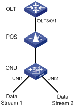
Figure 1-9 Network diagram for UNI priority remarking configuration
Networking and Configuration Requirements
l Set the uplink bandwidth of the ONU to 50 Mbps.
l Configure the VLAN operation mode as transparent for both UNI 1 and UNI 2.
l Configure priority remarking for UNI 1: Remark tagged packets destined for the MAC address of 000A-EB7F-AAAB with CoS 3 precedence.
l Configure priority remarking for UNI 2: Remark tagged packets destined for the MAC address of 001B-EB7F-21AC with CoS 1 precedence.
Applicable Product Matrix
|
Product series |
Software version |
Hardware version |
|
S7500E Series Ethernet Switches |
Release 6300 |
All versions |
Configuration procedure
# Create ONU 3/0/1:1, and bind it to the ONU.
<Sysname> system-view
[Sysname] interface olt 3/0/1
[Sysname-Olt3/0/1] using onu 1
[Sysname-Olt3/0/1] quit
[Sysname] interface onu 3/0/1:1
[Sysname-Onu3/0/1:1] bind onuid 000f-e200-0104
# Set the uplink bandwidth of the ONU port to 50 Mbps (64 Kbps × 800).
[Sysname-Onu3/0/1:1] upstream-sla minimum-bandwidth 800 maximum-bandwidth 800
# Configure the VLAN operation mode as transparent for UNI 1 and UNI 2.
[Sysname-Onu3/0/1:1] uni 1 vlan-mode transparent
[Sysname-Onu3/0/1:1] uni 2 vlan-mode transparent
# Configure priority remarking for UNI 1 and UNI 2.
[Sysname-Onu3/0/1:1] uni 1 classification-marking index 1 queue 3 priority 3 dst-mac equal 000A-EB7F-AAAB
[Sysname-Onu3/0/1:1] uni 2 classification-marking index 1 queue 1 priority 1 dst-mac equal 001B-EB7F-21AC
After the configuration above is complete, when two streams (each 50 Mbps) from two UNIs of the ONU are being forwarded to the OLT, the packets destined for the MAC address of 001B-EB7F-21AC are dropped at forwarding congestion on the ONU port, because the CoS precedence of these packets is lower than that of the packets destined for the MAC address of 000A-EB7F-AAAB.
Complete configuration
#
interface Olt3/0/1
using onu 1
#
interface Onu3/0/1:1
bind onuid 000f-e200-0104
upstream-sla minimum-bandwidth 800 maximum-bandwidth 800
uni 1 classification-marking index 1 queue 3 priority 3 src-mac equal 000a-eb7f-aaab
uni 2 classification-marking index 1 queue 1 priority 1 src-mac equal 001b-eb7f-21ac
Configuration guidelines
Currently, up to eight rules can be configured for each UNI port on an H3C ONU.