- Table of Contents
-
- H3C Low-End and Mid-Range Ethernet Switches Configuration Examples(V1.01)
- 00-1Cover
- 01-Login Configuration Guide
- 02-VLAN Configuration Guide
- 03-GVRP Configuration Guide
- 04-Voice VLAN Configuration Guide
- 05-IP Addressing and Performance Configuration Guide
- 06-QinQ Configuration Guide
- 07-BPDU Tunnel Configuration Guide
- 08-VLAN Mapping Configuration Guide
- 09-MAC Address Table Management Configuration Guide
- 10-Link Aggregation Configuration Guide
- 11-IP Source Guard Configuration Guide
- 12-DLDP Configuration Guide
- 13-MSTP Configuration Guide
- 14-IPv4 Routing Configuration Guide
- 15-IPv6 Configuration Guide
- 16-IPv6 Routing Configuration Guide
- 17-IPv4 Multicast Configuration Guide
- 18-IPv6 Multicast Configuration Examples
- 19-802.1x Configuration Guide
- 20-AAA Configuration Guide
- 21-MAC Authentication Configuration Guide
- 22-Portal Configuration Guide
- 23-ARP Configuration Guide
- 24-DHCP Configuration Guide
- 25-ACL Configuration Guide
- 26-QoS Configuration Guide
- 27-Port Mirroring Configuration Guide
- 28-Cluster Management Configuration Guide
- 29-SNMP-RMON Configuration Guide
- 30-NTP Configuration Guide
- 31-FTP-TFTP Configuration Guide
- 32-UDP Helper Configuration Guide
- 33-Information Center Configuration Guide
- 34-DNS Configuration Guide
- 35-File System Management Configuration Guide
- 36-Remote Upgrade Configuration Guide
- 37-NQA Configuration Guide
- 38-VRRP Configuration Guide
- 39-SSH Configuration Guide
- 40-Port Security Configuration Guide
- 41-Port Isolation Configuration Guide
- 42-LLDP Configuration Guide
- 43-MCE Configuration Guide
- 44-PoE Configuration Guide
- 45-OAM Configuration Guide
- 46-Connectivity Fault Detection Configuration Guide
- 47-RRPP Configuration Guide
- 48-sFlow Configuration Guide
- 49-SSL-HTTPS Configuration Guide
- 50-PKI Configuration Guide
- 51-Track Configuration Guide
- 52-EPON-OLT Configuration Guide
- 53-Smart Link Configuration Guide
- 54-MPLS Configuration Guide
- Related Documents
-
| Title | Size | Download |
|---|---|---|
| 22-Portal Configuration Guide | 155.16 KB |
Portal Authentication Overview
Configuring Direct Portal Authenction
Networking and Configuration Requirements
Configuring Re-DHCP Portal Authentication
Networking and Configuration Requirements
Configuring Layer 3 Portal Authentication
Networking and Configuration Requirements
Configuring Direct Portal Authentication for EAD
Networking and Configuration Requirements
Portal Authentication Overview
Portal authentication, as its name implies, helps control access to the Internet. Portal authentication is also called web authentication and a website implementing portal authentication is called a portal website.
With portal authentication, an access device forces all users to log into the portal website at first. A user can access the free services provided on the portal website without authentication; but to access the Internet, the user must pass portal authentication on the portal website.
A user can access a known portal website and enter the username and password for authentication. This authentication mode is called active authentication. There is still another authentication mode, namely forced authentication, in which the access device forces a user trying to access the Internet through HTTP to log in to a portal website for authentication.
The portal feature provides the flexibility for Internet service providers (ISPs) to manage services. A portal website can, for example, present advertisements, and deliver community services and personalized services. In this way, broadband network providers, equipment providers, and content service providers form an industrial ecological system.
Configuring Direct Portal Authenction
Network Diagram
Figure 1-1 Network diagram for direct portal authentication configuration
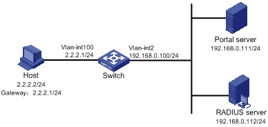
Networking and Configuration Requirements
l The switch is configured for direct portal authentication. Before portal authentication, users can access only the portal server. After passing portal authentication, they can access external networks.
l A RADIUS server serves as the authentication/accounting server.
Applicable Product Matrix
|
Product series |
Software version |
Hardware version |
|
S7500E Series Ethernet Switches |
Release 6100, Release 6300 |
All versions |
Configuration Procedure
![]()
You need to configure IP addresses for the devices as shown in Figure 1-1 and ensure that routes are available between devices.
Configure the access device (Switch):
1) Configure a RADIUS scheme
# Create a RADIUS scheme named rs1 and enter its view.
<Switch> system-view
[Switch] radius scheme rs1
# Set the server type to extended.
[Switch-radius-rs1] server-type extended
# Configure the primary authentication server, the primary accounting server, and the communication keys.
[Switch-radius-rs1] primary authentication 192.168.0.112
[Switch-radius-rs1] primary accounting 192.168.0.112
[Switch-radius-rs1] key authentication radius
[Switch-radius-rs1] key accounting radius
# Specify that the ISP domain name should not be included in the username sent to the RADIUS server.
[Switch-radius-rs1] user-name-format without-domain
[Switch-radius-rs1] quit
2) Configure an authentication domain
# Create an ISP domain named dm1 and enter its view.
[Switch] domain dm1
# Configure the ISP domain to use RADIUS scheme rs1.
[Switch-isp-dm1] authentication portal radius-scheme rs1
[Switch-isp-dm1] authorization portal radius-scheme rs1
[Switch-isp-dm1] accounting portal radius-scheme rs1
[Switch-isp-dm1] quit
# Configure dm1 as the default ISP domain, allowing all users to share the default authentication and accounting modes.
[Switch] domain default enable dm1
3) Configure portal authentication
# Configure the portal server as follows:
l Name: newpt
l IP address: 192.168.0.111
l Key: portal
l Port number: 50100
l URL: http://192.168.0.111/portal.
[Switch] portal server newpt ip 192.168.0.111 key portal port 50100 url http://192.168.0.111/portal
# Enable portal authentication on the interface connecting the host.
[Switch] interface vlan-interface 100
[Switch–Vlan-interface100] ip address 2.2.2.1 255.255.255.0
[Switch–Vlan-interface100] portal server newpt method direct
[Switch] quit
# Configure the IP address of the interface connected with the portal server.
[Switch] interface vlan-interface 2
[Switch–Vlan-interface2] ip address 192.168.0.100 255.255.255.0
[Switch–Vlan-interface2] quit
Complete Configuration
#
domain default enable dm1
#
#
portal server newpt ip 192.168.0.111 key portal url http://192.168.0.111/portal
#
radius scheme rs1
server-type extended
primary authentication 192.168.0.112
primary accounting 192.168.0.112
key authentication radius
key accounting radius
user-name-format without-domain
#
domain dm1
authentication portal radius-scheme rs1
authorization portal radius-scheme rs1
accounting portal radius-scheme rs1
#
interface Vlan-interface2
ip address 192.168.0.100 255.255.255.0
#
interface Vlan-interface100
ip address 2.2.2.1 255.255.255.0
portal server newpt method direct
#
Configuration Guidelines
l The destination port number that the switch uses for sending packets to the portal server unsolicitedly must be the same as that the remote portal server actually uses.
l The portal server parameters can be modified only before the portal server is applied to an interface.
l The portal server to be referenced by a portal-enabled interface must exist.
Configuring Re-DHCP Portal Authentication
Network Diagram
Figure 1-2 Network diagram for re-DHCP portal authentication configuration
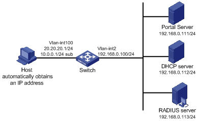
Networking and Configuration Requirements
l The switch is configured for re-DHCP authentication. Users obtain IP addresses through the DHCP server. Before portal authentication, they get private IP addresses. After passing portal authentication, they get public IP addresses and then can access the Internet.
l A RADIUS server serves as the authentication/accounting server.
Applicable Product Matrix
|
Product series |
Software version |
Hardware version |
|
S7500E Series Ethernet Switches |
Release 6100, Release 6300 |
All versions |
Configuration Procedure
![]()
l For re-DHCP authentication, you need to configure a public address pool (20.20.20.0/24, in this example) and a private address pool (10.0.0.0/24, in this example) on the DHCP server. The configuration steps are omitted. For DHCP configuration information, refer to DHCP Configuration in this manual.
l For re-DHCP authentication, the access device must be configured as a DHCP relay agent (instead of a DHCP server) and the portal-enabled interface must be configured with a primary IP address (a public IP address) and a secondary IP address (a private IP address).
l You need to configure IP addresses for the devices as shown in Figure 1-2 and ensure that routes are available between devices.
l The following describes only the configurations related to re-DHCP authentication mode. For configurations about the RADIUS scheme and ISP domain, refer to Configuring Direct Portal Authenction.
Configure the access device:
# Configure the portal server as follows:
l Name: newpt
l IP address: 192.168.0.111
l Key: portal
l Port number: 50100
l URL: http://192.168.0.111/portal.
<Switch> system-view
[Switch] portal server newpt ip 192.168.0.111 key portal port 50100 url http://192.168.0.111/portal
# Configure the access device as a DHCP relay agent, and enable the invalid address check function.
[Switch] dhcp enable
[Switch] dhcp relay server-group 0 ip 192.168.0.112
[Switch] interface vlan-interface 100
[Switch–Vlan-interface100] ip address 20.20.20.1 255.255.255.0
[Switch–Vlan-interface100] ip address 10.0.0.1 255.255.255.0 sub
[Switch-Vlan-interface100] dhcp select relay
[Switch-Vlan-interface100] dhcp relay server-select 0
[Switch-Vlan-interface100] dhcp relay address-check enable
# Enable re-DHCP portal authentication on the interface connecting the host.
[Switch–Vlan-interface100] portal server newpt method redhcp
[Switch–Vlan-interface100] quit
# Configure the IP address of the interface connected with the portal server.
[Switch] interface vlan-interface 2
[Switch–Vlan-interface2] ip address 192.168.0.100 255.255.255.0
[Switch–Vlan-interface2] quit
Complete Configuration
#
domain default enable dm1
#
portal server newpt ip 192.168.0.111 key portal url http://192.168.0.111/portal
#
radius scheme rs1
server-type extended
primary authentication 192.168.0.112
primary accounting 192.168.0.112
key authentication radius
key accounting radius
user-name-format without-domain
#
domain dm1
authentication portal radius-scheme rs1
authorization portal radius-scheme rs1
accounting portal radius-scheme rs1
#
interface Vlan-interface2
ip address 192.168.0.100 255.255.255.0
#
interface Vlan-interface100
ip address 20.20.20.1 255.255.255.0
ip address 10.0.0.1 255.255.255.0 sub
dhcp select relay
dhcp relay server-select 0
dhcp relay address-check enable
portal server newpt method redhcp
#
Configuration Guidelines
In re-DHCP authentication mode, a user can send packets using a public IP address before portal authentication, but the corresponding response packets are restricted.
Configuring Layer 3 Portal Authentication
Differences between Layer 3 and non-Layer 3 authentication modes:
l Networking mode
The Layer 3 portal authentication mode allows Layer 3 forwarding devices to be present between the authentication client and the access device, while the non-Layer 3 portal authentication mode does not.
l User identifier
In Layer 3 authentication mode, a client is uniquely identified by an IP address. This is because the mode supports Layer 3 forwarding devices between the authentication client and the access device and the access device does not learn the MAC address of the authentication client. In non-Layer 3 authentication mode, a client is uniquely identified by the combination of its IP address and MAC address because the access device can learn the MAC address of the authentication client.
Due to the above differences,
l In Layer-3 authentication mode, a new portal authentication will be triggered when the IP address of the authentication client changes even if its MAC address remains the same.
l In non-Layer 3 authentication mode, a new portal authentication will be triggered only when both the MAC and IP address of the authentication client are changed.
Network Diagram
Figure 1-3 Network diagram for Layer 3 portal authentication configuration
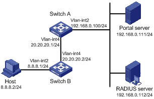
Networking and Configuration Requirements
l Switch A is configured for Layer 3 portal authentication. Before portal authentication, users can access only the portal server. After passing portal authentication, they can access external networks.
l A RADIUS server serves as the authentication/accounting server.
Applicable Product Matrix
|
Product series |
Software version |
Hardware version |
|
S7500E Series Ethernet Switches |
Release 6100, Release 6300 |
All versions |
Configuration Procedure
![]()
l You need to configure IP addresses for the devices as shown in Figure 1-3 and ensure that routes are available between devices.
l The following describes only the major configurations related to Layer 3 portal authentication. For configurations about the RADIUS scheme and ISP domain, refer to Configuring Direct Portal Authenction.
Configure Switch A:
# Configure the portal server as follows:
l Name: newpt
l IP address: 192.168.0.111
l Key: portal
l Port number: 50100
l URL: http://192.168.0.111/portal.
<SwitchA> system-view
[SwitchA] portal server newpt ip 192.168.0.111 key portal port 50100 url http://192.168.0.111/portal
# Enable portal authentication on the interface connecting Switch B.
[SwitchA] interface vlan-interface 4
[SwitchA–Vlan-interface4] ip address 20.20.20.1 255.255.255.0
[SwitchA–Vlan-interface4] portal server newpt method layer3
[SwitchA–Vlan-interface4] quit
# Configure the IP address of the interface connected with the portal server.
[SwitchA] interface vlan-interface 2
[SwitchA–Vlan-interface2] ip address 192.168.0.100 255.255.255.0
[SwitchA–Vlan-interface2] quit
On Switch B, you need to configure a default route to subnet 192.168.0.0/24, setting the next hop as 20.20.20.1. The configuration steps are omitted.
Complete Configuration
#
domain default enable dm1
#
portal server newpt ip 192.168.0.111 key portal url http://192.168.0.111/portal
#
radius scheme rs1
server-type extended
primary authentication 192.168.0.112
primary accounting 192.168.0.112
key authentication radius
key accounting radius
user-name-format without-domain
security-policy-server 192.168.0.113
#
domain dm1
authentication portal radius-scheme rs1
authorization portal radius-scheme rs1
accounting portal radius-scheme rs1
#
interface Vlan-interface2
ip address 192.168.0.100 255.255.255.0
#
interface Vlan-interface4
ip address 20.20.20.1 255.255.255.0
portal server newpt method layer3
#
Configuration Guidelines
Only Layer 3 authentication mode can be used in applications with Layer 3 forwarding devices present between the authentication clients and the access device. However, Layer 3 authentication does not require any Layer 3 forwarding devices between the access device and the authentication clients.
Configuring Direct Portal Authentication for EAD
Network Diagram
Figure 1-4 Network diagram for configuring direct portal authentication for EAD
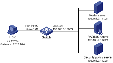
Networking and Configuration Requirements
l The switch is configured for direct portal authentication and EAD authentication. When users have passed identity authentication but have not passed security authentication, they can access only subnet 192.168.0.0/24. After passing security authentication, they can access the Internet.
l A RADIUS server serves as the authentication/accounting server.
l A security policy server is configured.
Applicable Product Matrix
|
Product series |
Software version |
Hardware version |
|
S7500E Series Ethernet Switches |
Release 6100, Release 6300 |
All versions |
Configuration Procedure
![]()
You need to configure IP addresses for the devices as shown in Figure 1-4 and ensure that routes are available between devices.
Configure the access device (Switch):
1) Configure a RADIUS scheme
# Create a RADIUS scheme named rs1 and enter its view.
<Switch> system-view
[Switch] radius scheme rs1
# Set the server type to extended.
[Switch-radius-rs1] server-type extended
# Configure the primary authentication server, the primary accounting server, and the communication keys.
[Switch-radius-rs1] primary authentication 192.168.0.112
[Switch-radius-rs1] primary accounting 192.168.0.112
[Switch-radius-rs1] key accounting radius
[Switch-radius-rs1] key authentication radius
[Switch-radius-rs1] user-name-format without-domain
# Configure the IP address of the security policy server.
[Switch-radius-rs1] security-policy-server 192.168.0.113
[Switch-radius-rs1] quit
2) Configure an authentication domain
# Create an ISP domain named dm1 and enter its view.
[Switch] domain dm1
# Configure the ISP domain to use RADIUS scheme rs1.
[Switch-isp-dm1] authentication portal radius-scheme rs1
[Switch-isp-dm1] authorization portal radius-scheme rs1
[Switch-isp-dm1] accounting portal radius-scheme rs1
[Switch-isp-dm1] quit
# Configure dm1 as the default ISP domain, allowing all users to share the authentication and accounting modes of the default domain.
[Switch] domain default enable dm1
3) Configure the ACL (ACL 3000 ) for restricted resources and the ACL (ACL 3001) for unrestricted resources
[Switch] acl number 3000
[Switch-acl-adv-3000] rule permit ip destination 192.168.0.0 0.0.0.255
[Switch-acl-adv-3000] quit
[Switch] acl number 3001
[Switch-acl-adv-3001] rule permit ip
[Switch-acl-adv-3001] quit
![]()
On the security policy server, you need to specify ACL 3000 as the isolation ACL and ACL 3001 as the security ACL.
4) Configure portal authentication
# Configure the portal server as follows:
l Name: newpt
l IP address: 192.168.0.111
l Key: portal
l Port number: 50100
l URL: http://192.168.0.111/portal.
[Switch] portal server newpt ip 192.168.0.111 key portal port 50100 url http://192.168.0.111/portal
# Enable portal authentication on the interface connecting the host.
[Switch] interface vlan-interface 100
[Switch–Vlan-interface100] ip address 2.2.2.1 255.255.255.0
[Switch–Vlan-interface100] portal server newpt method direct
[Switch] quit
# Configure the IP address of the interface connected with the portal server.
[Switch] interface vlan-interface 2
[Switch–Vlan-interface2] ip address 192.168.0.100 255.255.255.0
Complete Configuration
#
domain default enable dm1
#
#
portal server newpt ip 192.168.0.111 key portal url http://192.168.0.111/portal
#
radius scheme rs1
server-type extended
primary authentication 192.168.0.112
primary accounting 192.168.0.112
key authentication radius
key accounting radius
user-name-format without-domain
security-policy-server 192.168.0.113
#
domain dm1
authentication portal radius-scheme rs1
authorization portal radius-scheme rs1
accounting portal radius-scheme rs1
#
acl number 3000
rule permit ip destination 192.168.0.0 0.0.0.255
#
acl number 3001
rule permit ip
#
interface Vlan-interface2
ip address 192.168.0.100 255.255.255.0
#
interface Vlan-interface100
ip address 2.2.2.1 255.255.255.0
portal server newpt method direct
#
Configuration Guidelines
For configuration about the security policy server, refer to CAMS EAD Security Policy Component User Manual.