- Table of Contents
-
- H3C Low-End and Mid-Range Ethernet Switches Configuration Examples(V1.01)
- 00-1Cover
- 01-Login Configuration Guide
- 02-VLAN Configuration Guide
- 03-GVRP Configuration Guide
- 04-Voice VLAN Configuration Guide
- 05-IP Addressing and Performance Configuration Guide
- 06-QinQ Configuration Guide
- 07-BPDU Tunnel Configuration Guide
- 08-VLAN Mapping Configuration Guide
- 09-MAC Address Table Management Configuration Guide
- 10-Link Aggregation Configuration Guide
- 11-IP Source Guard Configuration Guide
- 12-DLDP Configuration Guide
- 13-MSTP Configuration Guide
- 14-IPv4 Routing Configuration Guide
- 15-IPv6 Configuration Guide
- 16-IPv6 Routing Configuration Guide
- 17-IPv4 Multicast Configuration Guide
- 18-IPv6 Multicast Configuration Examples
- 19-802.1x Configuration Guide
- 20-AAA Configuration Guide
- 21-MAC Authentication Configuration Guide
- 22-Portal Configuration Guide
- 23-ARP Configuration Guide
- 24-DHCP Configuration Guide
- 25-ACL Configuration Guide
- 26-QoS Configuration Guide
- 27-Port Mirroring Configuration Guide
- 28-Cluster Management Configuration Guide
- 29-SNMP-RMON Configuration Guide
- 30-NTP Configuration Guide
- 31-FTP-TFTP Configuration Guide
- 32-UDP Helper Configuration Guide
- 33-Information Center Configuration Guide
- 34-DNS Configuration Guide
- 35-File System Management Configuration Guide
- 36-Remote Upgrade Configuration Guide
- 37-NQA Configuration Guide
- 38-VRRP Configuration Guide
- 39-SSH Configuration Guide
- 40-Port Security Configuration Guide
- 41-Port Isolation Configuration Guide
- 42-LLDP Configuration Guide
- 43-MCE Configuration Guide
- 44-PoE Configuration Guide
- 45-OAM Configuration Guide
- 46-Connectivity Fault Detection Configuration Guide
- 47-RRPP Configuration Guide
- 48-sFlow Configuration Guide
- 49-SSL-HTTPS Configuration Guide
- 50-PKI Configuration Guide
- 51-Track Configuration Guide
- 52-EPON-OLT Configuration Guide
- 53-Smart Link Configuration Guide
- 54-MPLS Configuration Guide
- Related Documents
-
| Title | Size | Download |
|---|---|---|
| 46-Connectivity Fault Detection Configuration Guide | 80.28 KB |
Table of Contents
1 Connectivity Fault Detection Configuration Guide
Configuring Connectivity Fault Detection
Configuring Connectivity Fault Detection
Network Diagram
Figure 1-1 Network diagram for Connectivity Fault Detection configuration
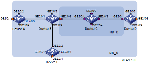
l Networking and Configuration RequirementsConfigure two maintenance domains (MDs) in the network: MD_A (light blue) and MD_B (dark blue), with the maintenance levels being 5 and 3 respectively. Define the edge ports of each MD, and the MD to which each port belongs. The VLAN IDs of the maintenance associations (MAs) in the two MD are all 100.
l Find all the edge ports of each MD, and determine the directions (inward-facing or outward-facing) of the maintenance association end points (MEPs) configured in each MD according to the location of the MD; specify for each MEP an ID that is unique within its maintenance association (MA); specify a remote MEP for each MEP and enable these MEPs.
l Determine the devices that need to be configured with maintenance association intermediate points (MIPs), and configure the appropriate rule for generating MIPs.
l After detecting a link fault using the continuity check (CC) function, you can use the loopback (LB) function to trace the fault source.
l After obtaining the status of the whole network using the CC function, you can use the linktrace (LT) function to determine the path or locate the fault.
Applicable Product Matrix
|
Product series |
Software version |
Hardware version |
|
S7500E Series Etherne Switches |
Release 6300 |
All versions |
Configuration Procedure
Configuring Service Instance
According to the network diagram, You should perform the following configurations:
l Configure MD_A on Device A and Device E
l Configure MD_B on Device C
l Configure MD_A and MD_B on Device B and Device D
l Configure an MA in each MD
1) Configuration on SwitchA (configuration on Device E is the same as that on Device B)
<DeviceA> system-view
[DeviceA] cfd enable
[DeviceA] cfd md MD_A level 5
[DeviceA] cfd ma MA_MD_A md MD_A vlan 100
[DeviceA] cfd service-instance 1 md MD_A ma MA_MD_A
2) Configuration on Device C
<DeviceC> system-view
[DeviceC] cfd enable
[DeviceC] cfd md MD_B level 3
[DeviceC] cfd ma MA_MD_B md MD_B vlan 100
[DeviceC] cfd service-instance 2 md MD_B ma MA_MD_B
3) Configuration on Device B (configuration on Device D is the same as that on Device B)
<DeviceB> system-view
[DeviceB] cfd enable
[DeviceB] cfd md MD_A level 5
[DeviceB] cfd ma MA_MD_A md MD_A vlan 100
[DeviceB] cfd service-instance 1 md MD_A ma MA_MD_A
[DeviceB] cfd md MD_B level 3
[DeviceB] cfd ma MA_MD_B md MD_B vlan 100
[DeviceB] cfd service-instance 2 md MD_B ma MA_MD_B
Configuring MEP and Enabling CC on it
l In MD_B, there are two edge ports: GigabitEthernet 2/0/3 on Device B and GigabitEthernet 2/0/1 on Device D. Configure outward-facing MEPs on the two ports respectively.
l In MD_A and MD_B, each MEP checks the messages from other MEPs. The IDs of these MEPs are listed in .
Table 1-1 IDs assigned to the MEPs
|
Device |
Port |
ID |
|
DeviceA |
GigabitEthernet2/0/1 |
1001 |
|
DeviceB |
GigabitEthernet2/0/3 |
2001 |
|
DeviceD |
GigabitEthernet2/0/1 |
4001 |
|
GigabitEthernet2/0/3 |
4002 |
|
|
DeviceE |
GigabitEthernet2/0/4 |
5001 |
2) On Device A
<DeviceA> system-view
[DeviceA] interface gigabitethernet 1/0/1
[DeviceA-GigabitEthernet1/0/1] cfd mep 1001 service-instance 1 inbound
[DeviceA-GigabitEthernet1/0/1] cfd remote-mep 5001 service-instance 1 mep 1001
[DeviceA-GigabitEthernet1/0/1] cfd remote-mep 4002 service-instance 1 mep 1001
[DeviceA-GigabitEthernet1/0/1] cfd mep service-instance 1 mep 1001 enable
[DeviceA-GigabitEthernet1/0/1] cfd cc service-instance 1 mep 1001 enable
3) On Device B
<DeviceB> system-view
[DeviceB] interface gigabitethernet 1/0/3
[DeviceB-GigabitEthernet1/0/3] cfd mep 2001 service-instance 2 outbound
[DeviceB-GigabitEthernet1/0/3] cfd remote-mep 4001 service-instance 2 mep 2001
[DeviceB-GigabitEthernet1/0/3] cfd mep service-instance 2 mep 2001 enable
[DeviceB-GigabitEthernet1/0/3] cfd cc service-instance 2 mep 2001 enable
4) On Device D
<DeviceD> system-view
[DeviceD] interface gigabitethernet 1/0/1
[DeviceD-GigabitEthernet1/0/1] cfd mep 4001 service-instance 2 outbound
[DeviceD-GigabitEthernet1/0/1] cfd remote-mep 2001 service-instance 2 mep 4001
[DeviceD-GigabitEthernet1/0/1] cfd mep service-instance 2 mep 4001 enable
[DeviceD-GigabitEthernet1/0/1] cfd cc service-instance 2 mep 4001 enable
[DeviceD-GigabitEthernet1/0/1] interface gigabitethernet 1/0/3
[DeviceD-GigabitEthernet1/0/3] cfd mep 4002 service-instance 1 inbound
[DeviceD-GigabitEthernet1/0/3] cfd remote-mep 1001 service-instance 1 mep 4002
[DeviceD-GigabitEthernet1/0/3] cfd remote-mep 5001 service-instance 1 mep 4002
[DeviceD-GigabitEthernet1/0/3] cfd mep service-instance 1 mep 4002 enable
[DeviceD-GigabitEthernet1/0/3] cfd cc service-instance 1 mep 4002 enable
5) On Device E
<DeviceE> system-view
[DeviceE] interface gigabitethernet 1/0/4
[DeviceE-GigabitEthernet1/0/4] cfd mep 5001 service-instance 1 inbound
[DeviceE-GigabitEthernet1/0/4] cfd remote-mep 1001 service-instance 1 mep 5001
[DeviceE-GigabitEthernet1/0/4] cfd remote-mep 4002 service-instance 1 mep 5001
[DeviceE-GigabitEthernet1/0/4] cfd mep service-instance 1 mep 5001 enable
[DeviceE-GigabitEthernet1/0/4] cfd cc service-instance 1 mep 5001 enable
Configuring the Rules for Generating MIPs
By default, MIP is not configured on a device. If MIPs are to be configured on each port in the MD, you should choose the default rule. If MIPs are to be configured only when the low level MDs having MEP, you should choose the explicit rule.
l In MD_A, Device B is designed to have MIPs when its port is configured with low level MEPs. In this case, port GigabitEthernet 1/0/3 is configured with MEPs of MD_B, and the MIPs of MD_A can be configured on this port. Based on the design, you should configure the MIP generation rule of MD_A to explicit on Device B.
l The MIPs of MD_B are designed on Device C, and are configured on all ports. Based on this design, the MIP generation rule should be configured as default.
1) Configure Device B
<DeviceB> system-view
[DeviceB] cfd mip-rule explicit service-instance 1
2) Configure Device C
<DeviceC> system-view
[DeviceC] cfd mip-rule default service-instance 2
Configuring LB on MEPs
Use the LB function to trace the fault source after CC detects a link fault.
As shown in Figure 1-1, enable LB on Device A so that Device A can send LBM messages to MEPs on Device D.
# Configure Device A
<DeviceA> system-view
[DeviceA] cfd loopback service-instance 1 mep 1001 target-mep 4002
Configuring LT on MEPs
Use the LT function to find the path and locate the fault after you obtain the state of the entire network through the CC.
As shown in Figure 1-1, enable LT on Device A so that Device A can send LTM messages to the MEP on Device D.
# Configure Device A
<DeviceA> system-view
[DeviceA] cfd linktrace service-instance 1 mep 1001 target-mep 4002
Complete configuration
l Configuration on Device A
#
cfd enable
cfd md MD_A level 5
cfd ma MA_MD_A md MD_A vlan 100
cfd service-instance 1 md MD_A ma MA_MD_A
cfd linktrace service-instance 1 mep 1001 target-mep 4002
cfd loopback service-instance 1 mep 1001 target-mep 4002
#
interface GigabitEthernet2/0/1
cfd mep 1001 service-instance 1 inbound
cfd mep service-instance 1 mep 1001 enable
cfd cc service-instance 1 mep 1001 enable
cfd remote-mep 4002 service-instance 1 mep 1001
cfd remote-mep 5001 service-instance 1 mep 1001
l Configuration on Device B
#
cfd enable
cfd md MD_B level 3
cfd ma MA_MD_B md MD_B vlan 100
cfd service-instance 2 md MD_B ma MA_MD_B
cfd md MD_A level 5
cfd ma MA_MD_A md MD_A vlan 100
cfd service-instance 1 md MD_A ma MA_MD_A
cfd mip-rule explicit service-instance 1
#
interface GigabitEthernet2/0/3
cfd mep 2001 service-instance 2 inbound
cfd mep service-instance 2 mep 2001 enable
cfd cc service-instance 2 mep 2001 enable
cfd remote-mep 4001 service-instance 2 mep 2001
l Configuration on Device C
#
cfd enable
cfd md MD_B level 3
cfd ma MA_MD_B md MD_B vlan 100
cfd service-instance 2 md MD_B ma MA_MD_B
cfd mip-rule default service-instance 2
l Configuration on Device D
#
cfd enable
cfd md MD_B level 3
cfd ma MA_MD_B md MD_B vlan 100
cfd service-instance 2 md MD_B ma MA_MD_B
cfd md MD_A level 5
cfd ma MA_MD_A md MD_A vlan 100
cfd service-instance 1 md MD_A ma MA_MD_A
#
interface GigabitEthernet2/0/1
cfd mep 4001 service-instance 2 outbound
cfd mep service-instance 2 mep 4001 enable
cfd cc service-instance 2 mep 4001 enable
cfd remote-mep 2001 service-instance 2 mep 4001
#
#
interface GigabitEthernet2/0/3
cfd mep 4002 service-instance 1 inbound
cfd mep service-instance 1 mep 4002 enable
cfd cc service-instance 1 mep 4002 enable
cfd remote-mep 1001 service-instance 1 mep 4002
cfd remote-mep 5001 service-instance 1 mep 4002
l Configuration on Device E
#
cfd enable
cfd md MD_A level 5
cfd ma MA_MD_A md MD_A vlan 100
cfd service-instance 1 md MD_A ma MA_MD_A
#
interface GigabitEthernet2/0/4
cfd mep 5001 service-instance 1 outbound
cfd mep service-instance 1 mep 5001 enable
cfd cc service-instance 1 mep 5001 enable
cfd remote-mep 1001 service-instance 1 mep 5001
cfd remote-mep 4002 service-instance 1 mep 5001
Configuration guidelines
The operations of creating an MD, creating an MA, creating a service instance must be performed in strict order.