- Table of Contents
-
- H3C Low-End and Mid-Range Ethernet Switches Configuration Examples(V1.01)
- 00-1Cover
- 01-Login Configuration Guide
- 02-VLAN Configuration Guide
- 03-GVRP Configuration Guide
- 04-Voice VLAN Configuration Guide
- 05-IP Addressing and Performance Configuration Guide
- 06-QinQ Configuration Guide
- 07-BPDU Tunnel Configuration Guide
- 08-VLAN Mapping Configuration Guide
- 09-MAC Address Table Management Configuration Guide
- 10-Link Aggregation Configuration Guide
- 11-IP Source Guard Configuration Guide
- 12-DLDP Configuration Guide
- 13-MSTP Configuration Guide
- 14-IPv4 Routing Configuration Guide
- 15-IPv6 Configuration Guide
- 16-IPv6 Routing Configuration Guide
- 17-IPv4 Multicast Configuration Guide
- 18-IPv6 Multicast Configuration Examples
- 19-802.1x Configuration Guide
- 20-AAA Configuration Guide
- 21-MAC Authentication Configuration Guide
- 22-Portal Configuration Guide
- 23-ARP Configuration Guide
- 24-DHCP Configuration Guide
- 25-ACL Configuration Guide
- 26-QoS Configuration Guide
- 27-Port Mirroring Configuration Guide
- 28-Cluster Management Configuration Guide
- 29-SNMP-RMON Configuration Guide
- 30-NTP Configuration Guide
- 31-FTP-TFTP Configuration Guide
- 32-UDP Helper Configuration Guide
- 33-Information Center Configuration Guide
- 34-DNS Configuration Guide
- 35-File System Management Configuration Guide
- 36-Remote Upgrade Configuration Guide
- 37-NQA Configuration Guide
- 38-VRRP Configuration Guide
- 39-SSH Configuration Guide
- 40-Port Security Configuration Guide
- 41-Port Isolation Configuration Guide
- 42-LLDP Configuration Guide
- 43-MCE Configuration Guide
- 44-PoE Configuration Guide
- 45-OAM Configuration Guide
- 46-Connectivity Fault Detection Configuration Guide
- 47-RRPP Configuration Guide
- 48-sFlow Configuration Guide
- 49-SSL-HTTPS Configuration Guide
- 50-PKI Configuration Guide
- 51-Track Configuration Guide
- 52-EPON-OLT Configuration Guide
- 53-Smart Link Configuration Guide
- 54-MPLS Configuration Guide
- Related Documents
-
| Title | Size | Download |
|---|---|---|
| 15-IPv6 Configuration Guide | 261.59 KB |
Networking and Configuration Requirements
Configuring IPv6 Manual Tunnel
Networking and Configuration Requirements
Configuring Automatic IPv4-Compatible IPv6 Tunnel
Networking and Configuration Requirements
Configuring Automatic 6to4 Tunnel
Networking and Configuration Requirements
Networking and Configuration Requirements
1 IPv6 Configuration Guide
Configuring IPv6 Basics
To enable a host to access a public IPv6 network, you need to assign an IPv6 global unicast address to the switch.
IPv6 site-local addresses and aggregatable global unicast addresses can be configured in the following ways:
l EUI-64 format: When the EUI-64 format is adopted to form IPv6 addresses, the IPv6 address prefix of an interface is the configured prefix and the interface identifier is derived from the link-layer address of the interface.
l Manual configuration: IPv6 site-local addresses or aggregatable global unicast addresses are configured manually.
IPv6 link-local addresses can be configured in either of the following ways:
l Automatic generation: The device automatically generates a link-local address for an interface according to the link-local address prefix (FE80::/64) and the link-layer address of the interface.
l Manual assignment: IPv6 link-local addresses can be assigned manually.
1.1.1 Network Diagram
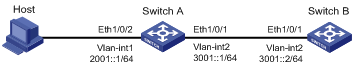
Figure 1-1 Network diagram for IPv6 basics configuration
Networking and Configuration Requirements
l Host, Switch A and Switch B are directly connected through Ethernet ports. Add the Ethernet ports into corresponding VLANs, configure IPv6 addresses for the VLAN interfaces and verify the connectivity between them.
l The aggregatable global unicast addresses of VLAN-interface 2 and VLAN-interface 1 on Switch A are 3001::1/64 and 2001::1/64, respectively.
l The aggregatable global unicast address of VLAN-interface 2 on Switch B is 3001::2/64, and a route to Host is available.
l IPv6 is enabled for Host to automatically get an IPv6 address through IPv6 ND.
Applicable Product Matrix
|
Product series |
Software version |
Hardware version |
|
S3610 Series Ethernet Switches |
Release 5301, Release 5303 |
All versions |
|
S5510 Series Ethernet Switches |
Release 5301, Release 5303 |
All versions |
|
S5500-SI Series Ethernet Switches |
Release 1207 |
All versions except S5500-20TP-SI |
|
Release 1301 |
S5500-20TP-SI |
|
|
S5500-EI Series Ethernet Switches |
Release 2102 |
All versions |
|
S7500E Series Ethernet Switches |
Release 6100, Release 6300 |
All versions |
Configuration Procedure
![]()
l The corresponding VLAN interfaces have been created on the switch.
l Before enabling IPv6 on an S3610/S5510 series Ethernet switch, you need to configure the device to operate in the IPv4/IPv6 dual-stack mode by using the switch-mode dual-ipv4-ipv6 command. Otherwise, IPv6 packets cannot be forwarded on the device even if IPv6 is enabled. The protocol stack changed by using the switch-mode command takes effect at the next reboot.
1) Configure Switch A
# Enable IPv6.
<SwitchA> system-view
[SwitchA] ipv6
# Specify an aggregatable global unicast address for VLAN-interface 2.
[SwitchA] interface vlan-interface 2
[SwitchA-Vlan-interface2] ipv6 address 3001::1/64
[SwitchA-Vlan-interface2] quit
# Specify an aggregatable global unicast address for VLAN-interface 1, and allow it to advertise RA messages (no interface advertises RA messages by default).
[SwitchA] interface vlan-interface 1
[SwitchA-Vlan-interface1] ipv6 address 2001::1/64
[SwitchA-Vlan-interface1] undo ipv6 nd ra halt
2) Configure Switch B
# Enable IPv6.
<SwitchB> system-view
[SwitchB] ipv6
# Configure an aggregatable global unicast address for VLAN-interface 2.
[SwitchB] interface vlan-interface 2
[SwitchB-Vlan-interface2] ipv6 address 3001::2/64
[SwitchB-Vlan-interface2] quit
# Configure an IPv6 static route with destination IP address 2001::/64 and next hop address 3001::1.
[SwitchB] ipv6 route-static 2001:: 64 3001::1
3) Configure Host
Enable IPv6 for Host to automatically get an IPv6 address through IPv6 ND.
[SwitchA] display ipv6 neighbors interface ethernet 1/0/2
Type: S-Static D-Dynamic
IPv6 Address Link-layer VID Interface State T Age
FE80::215:E9FF:FEA6:7D14 0015-e9a6-7d14 1 Eth1/0/2 STALE D 1238
2001::15B:E0EA:3524:E791 0015-e9a6-7d14 1 Eth1/0/2 STALE D 1248
The above information shows that the IPv6 aggregatable global unicast address that Host obtained is 2001::15B:E0EA:3524:E791.
4) Configuration verification
# Display the IPv6 interface settings on Switch.
[SwitchA] display ipv6 interface vlan-interface 2
[SwitchA] display ipv6 interface vlan-interface 1
[SwitchB] display ipv6 interface vlan-interface 2
# Ping Switch A and Switch B on Host, and ping Switch A and Host on Switch B to verify the connectivity between them.
![]()
When you ping a link-local address, you should use the –i parameter to specify an interface for the link-local address.
[SwitchB] ping ipv6 -c 1 3001::1
PING 3001::1 : 56 data bytes, press CTRL_C to break
Reply from 3001::1
bytes=56 Sequence=1 hop limit=64 time = 2 ms
--- 3001::1 ping statistics ---
1 packet(s) transmitted
1 packet(s) received
0.00% packet loss
round-trip min/avg/max = 2/2/2 ms
[SwitchB-Vlan-interface2] ping ipv6 -c 1 2001::15B:E0EA:3524:E791
PING 2001::15B:E0EA:3524:E791 : 56 data bytes, press CTRL_C to break
Reply from 2001::15B:E0EA:3524:E791
bytes=56 Sequence=1 hop limit=63 time = 3 ms
--- 2001::15B:E0EA:3524:E791 ping statistics ---
1 packet(s) transmitted
1 packet(s) received
0.00% packet loss
round-trip min/avg/max = 3/3/3 ms
As shown in the output information, you can successfully ping Switch B and Switch A from Host.
Complete Configuration
1) Configure Switch A
#
ipv6
#
interface Vlan-interface1
ipv6 address 2001::1/64
undo ipv6 nd ra halt
#
interface Vlan-interface2
ipv6 address 3001::1/64
#
2) Configure Switch B
#
ipv6
#
interface Vlan-interface2
ipv6 address 3001::2/64
#
ipv6 route-static 2001:: 64 3001::1
#
Configuration Guidelines
l After an IPv6 site-local address or aggregatable global unicast address is configured for an interface, a link-local address is generated automatically. The automatically generated link-local address is the same as that generated by using the ipv6 address auto link-local command.
l Manual assignment takes precedence over automatic generation. That is, if you first adopt automatic generation and then manual assignment, the manually assigned link-local address will overwrite the automatically generated one. If you first adopt manual assignment and then automatic generation, the automatically generated link-local address will not take effect and the link-local address of an interface is still the manually assigned one. If you delete the manually assigned address, the automatically generated link-local address is validated.
Configuring IPv6 Manual Tunnel
The IPv6 over IPv4 tunneling mechanism encapsulates an IPv4 header in IPv6 data packets so that IPv6 packets can pass an IPv4 network through a tunnel to achieve interworking between isolated IPv6 networks.
According to the way the IPv4 address of the tunnel destination is acquired, tunnels are classified as configured tunnels and automatic tunnels.
l If the IPv4 address of the tunnel destination cannot be automatically acquired from the destination address of the IPv6 packet, it needs to be configured manually. Such a tunnel is called a configured tunnel.
l If the IPv4 address is embedded into the IPv6 address, the IPv4 address of the tunnel destination can automatically be acquired from the destination address of the IPv6 packet. Such a tunnel is called an automatic tunnel.
According to the way an IPv6 packet is encapsulated, IPv6 over IPv4 tunnels are classified as the following types:
l IPv6 manual tunnel
l Automatic IPv4-compatible IPv6 tunnel
l 6to4 tunnel
l ISATAP tunnel
Among the above tunnels, the IPv6 manual tunnel is a configured tunnel, while the automatic IPv4-compatible IPv6 tunnel, the 6to4 tunnel, and intra-site automatic tunnel address protocol (ISATAP) tunnel are automatic tunnels.
Network Diagram
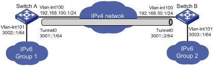
Figure 1-2 Network diagram for an IPv6 manual tunnel
Networking and Configuration Requirements
As shown in Figure 1-2, two IPv6 networks are connected to an IPv4 network through Switch A and Switch B, respectively. Configure an IPv6 manual tunnel between Switch A and Switch B to make the two IPv6 networks reachable to each other.
Applicable Product Matrix
|
Product series |
Software version |
Hardware version |
|
S3610 Series Ethernet Switches |
Release 5301, Release 5303 |
All versions |
|
S5510 Series Ethernet Switches |
Release 5301, Release 5303 |
All versions |
|
S5500-EI Series Ethernet Switches |
Release 2102 |
All versions |
|
S7500E Series Ethernet Switches |
Release 6100, Release 6300 |
All versions |
Configuration Procedure
![]()
l The corresponding VLAN interfaces have been created on Switch A and Switch B.
l The IP addresses of VLAN-interface 100 on Switch A and Switch B have been configured and an IPv4 route is available between the two interfaces.
l Before enabling IPv6 on an S3610/S5510 series Ethernet switch, you need to configure the device to operate in the IPv4/IPv6 dual-stack mode by using the switch-mode dual-ipv4-ipv6 command. Otherwise, IPv6 packets cannot be forwarded on the device even if IPv6 is enabled. The switch-mode command takes effect after the device is rebooted.
1) Configure Switch A
# Enable IPv6.
<SwitchA> system-view
[SwitchA] ipv6
# Configure an IPv4 address for VLAN-interface 100.
[SwitchA] interface vlan-interface 100
[SwitchA-Vlan-interface100] ip address 192.168.100.1 255.255.255.0
[SwitchA-Vlan-interface100] quit
# Configure an IPv6 address for VLAN-interface 101.
[SwitchA] interface vlan-interface 101
[SwitchA-Vlan-interface101] ipv6 address 3002::1 64
[SwitchA-Vlan-interface101] quit
# Configure a link aggregation group or a service loopback group. This configuration depends on the device model.
![]()
l A tunnel interface on an S7500E series Ethernet switch of software version Release 6300 must have a service loopback group referenced before sending or receiving packets. Make sure that the service loopback group to be referenced is already created; otherwise, the tunnel interface cannot be up and the switch cannot communicate through the tunnel.
l For a switch listed in the preceding applicable product matrix in section 1.2.3, except S7500E series Ethernet switches of software version Release 6300, its tunnel interface must have a link aggregation group referenced before sending or receiving packets. Make sure that the link aggregation group to be referenced is already created; otherwise, the tunnel interface cannot be up and the switch cannot communicate through the tunnel.
l Configure a link aggregation group. Note that you need to disable STP on a port before adding it into a link aggregation group.
[SwitchA] link-aggregation group 1 mode manual
[SwitchA] link-aggregation group 1 service-type tunnel
[SwitchA] interface GigabitEthernet 1/0/2
[SwitchA-GigabitEthernet1/0/2] stp disable
[SwitchA-GigabitEthernet1/0/2] port link-aggregation group 1
[SwitchA-GigabitEthernet1/0/2] quit
l Create a service loopback group. Note that you need to disable STP on a port before adding it to a service loopback group.
[SwitchA] service-loopback group 1 type tunnel
[SwitchA] interface GigabitEthernet 1/0/2
[SwitchA-GigabitEthernet1/0/2] stp disable
[SwitchA-GigabitEthernet1/0/2] port service-loopback group 1
[SwitchA-GigabitEthernet1/0/2] quit
# Configure a manual IPv6 tunnel.
[SwitchA] interface tunnel 0
[SwitchA-Tunnel0] ipv6 address 3001::1/64
[SwitchA-Tunnel0] source vlan-interface 100
[SwitchA-Tunnel0] destination 192.168.50.1
[SwitchA-Tunnel0] tunnel-protocol ipv6-ipv4
# Configure the tunnel to reference link aggregation group 1 or service loopback group 1 in tunnel interface view. This configuration depends on the device model.
l Configure the tunnel to reference link aggregation group 1 in tunnel interface view.
[SwitchA-Tunnel0] aggregation-group 1
[SwitchA-Tunnel0] quit
l Reference service loopback group 1 in tunnel interface view.
[SwitchA-Tunnel0] service-loopback-group 1
[SwitchA-Tunnel0] quit
# Configure a static route to IPv6 Group 2 through tunnel 0 on Switch A.
[SwitchA] ipv6 route-static 3003:: 64 tunnel 0
2) Configure Switch B
# Enable IPv6.
<SwitchB> system-view
[SwitchB] ipv6
# Configure an IPv4 address for VLAN-interface 100.
[SwitchB] interface vlan-interface 100
[SwitchB-Vlan-interface100] ip address 192.168.50.1 255.255.255.0
[SwitchB-Vlan-interface100] quit
# Configure an IPv6 address for VLAN-interface 101.
[SwitchB] interface vlan-interface 101
[SwitchB-Vlan-interface101] ipv6 address 3003::1 64
[SwitchB-Vlan-interface101] quit
# Configure a link aggregation group or a service loopback group. This configuration depends on the device model.
![]()
l A tunnel interface on an S7500E series Ethernet switch of software version Release 6300 must have a service loopback group referenced before sending or receiving packets. Make sure that the service loopback group to be referenced is already created; otherwise, the tunnel interface cannot be up and the switch cannot communicate through the tunnel.
l For a switch listed in the preceding applicable product matrix in section 1.2.3, except S7500E series Ethernet switches of software version Release 6300, its tunnel interface must have a link aggregation group referenced before sending or receiving packets. Make sure that the link aggregation group to be referenced is already created; otherwise, the tunnel interface cannot be up and the switch cannot communicate through the tunnel.
l Configure a link aggregation group. Note that you need to disable STP on a port before adding it into a link aggregation group.
[SwitchB] link-aggregation group 1 mode manual
[SwitchB] link-aggregation group 1 service-type tunnel
[SwitchB] interface GigabitEthernet 1/0/2
[SwitchB-GigabitEthernet1/0/2] stp disable
[SwitchB-GigabitEthernet1/0/2] port link-aggregation group 1
[SwitchB-GigabitEthernet1/0/2] quit
l Create a service loopback group. Note that you need to disable STP on a port before adding it to a service loopback group.
[SwitchB] service-loopback group 1 type tunnel
[SwitchB] interface GigabitEthernet 1/0/2
[SwitchB-GigabitEthernet1/0/2] stp disable
[SwitchB-GigabitEthernet1/0/2] port service-loopback group 1
[SwitchB-GigabitEthernet1/0/2] quit
# Configure an IPv6 manual tunnel.
[SwitchB] interface tunnel 0
[SwitchB-Tunnel0] ipv6 address 3001::2/64
[SwitchB-Tunnel0] source vlan-interface 100
[SwitchB-Tunnel0] destination 192.168.100.1
[SwitchB-Tunnel0] tunnel-protocol ipv6-ipv4
# Configure the tunnel to reference link aggregation group 1 or service loopback group 1. This configuration depends on the device model.
l Configure the tunnel to reference link aggregation group 1 in tunnel interface view.
[SwitchB-Tunnel0] aggregation-group 1
l Reference service loopback group 1 in tunnel interface view.
[SwitchB-Tunnel0] service-loopback-group 1
[SwitchB-Tunnel0] quit
# Configure a static route to IPv6 Group 1 through tunnel 0 on Switch B.
[SwitchB] ipv6 route-static 3002:: 64 tunnel 0
3) Configuration verification
After the above configurations, display the status of the tunnel interfaces on Switch A and Switch B, respectively.
[SwitchA] display ipv6 interface tunnel 0
[SwitchB] display ipv6 interface tunnel 0
# Ping the IPv6 address of the peer tunnel interface from Switch A.
[SwitchA] ping ipv6 3003::1
PING 3003::1 : 56 data bytes, press CTRL_C to break
Reply from 3003::1
bytes=56 Sequence=1 hop limit=64 time = 1 ms
Reply from 3003::1
bytes=56 Sequence=2 hop limit=64 time = 1 ms
Reply from 3003::1
bytes=56 Sequence=3 hop limit=64 time = 1 ms
Reply from 3003::1
bytes=56 Sequence=4 hop limit=64 time = 1 ms
Reply from 3003::1
bytes=56 Sequence=5 hop limit=64 time = 1 ms
--- 3003::1 ping statistics ---
5 packet(s) transmitted
5 packet(s) received
0.00% packet loss
round-trip min/avg/max = 1/1/1 ms
Complete Configuration
1) Configure Switch A
l Configure the tunnel to reference a link aggregation group on Switch A
#
ipv6
#
link-aggregation group 1 mode manual
link-aggregation group 1 service-type tunnel
#
interface Vlan-interface100
ip address 192.168.100.1 255.255.255.0
#
interface Vlan-interface101
ipv6 address 3002::1/64
#
interface GigabitEthernet1/0/2
stp disable
port link-aggregation group 1
#
interface Tunnel0
ipv6 address 3001::1/64
source Vlan-interface100
destination 192.168.50.1
aggregation-group 1
#
ipv6 route-static 3003:: 64 tunnel 0
#
l Configure the tunnel to reference a service loopback group on Switch A
#
ipv6
#
service-loopback group 1 type tunnel
#
interface Vlan-interface100
ip address 192.168.100.1 255.255.255.0
#
interface Vlan-interface101
ipv6 address 3002::1/64
#
interface GigabitEthernet1/0/2
port service-loopback group 1
#
interface Tunnel0
ipv6 address 3001::1/64
source Vlan-interface100
destination 192.168.50.1
service-loopback-group 1
#
ipv6 route-static 3003:: 64 tunnel 0
#
2) Configure SwitchB
l Configure the tunnel to reference a link aggregation group on Switch B
#
ipv6
#
link-aggregation group 1 mode manual
link-aggregation group 1 service-type tunnel
#
vlan 100
#
interface Vlan-interface100
ip address 192.168.100.1 255.255.255.0
#
interface Vlan-interface101
ipv6 address 3003::1/64
#
interface GigabitEthernet1/0/2
stp disable
port link-aggregation group 1
#
interface Tunnel0
ipv6 address 3001::1/64
source Vlan-interface100
destination 192.168.50.1
aggregation-group 1
#
ipv6 route-static 3002:: 64 tunnel 0
#
l Configure the tunnel to reference a service loopback group on Switch B
#
ipv6
#
service-loopback group 1 type tunnel
#
vlan 100
#
interface Vlan-interface100
ip address 192.168.100.1 255.255.255.0
#
interface Vlan-interface101
ipv6 address 3003::1/64
#
interface GigabitEthernet1/0/2
stp disable
port service-loopback group 1
#
interface Tunnel0
ipv6 address 3001::1/64
source Vlan-interface100
destination 192.168.50.1
service-loopback-group 1
#
ipv6 route-static 3002:: 64 tunnel 0
#
Configuration Guidelines
l The same tunnel type should be configured at both ends of the tunnel. Otherwise, packet delivery may fail.
l For a distributed device (such as S7500E series), a tunnel interface number is in the A/B/C format, where A, B, and C represent the slot number of a card, the slot number of a sub-card, and the tunnel interface number, respectively.
l When you create a tunnel interface on a distributed device (such as S7500E series), the slot of the tunnel interface is recommended to be that of the source interface, namely, the interface sending packets. In this way, the forwarding efficiency can be improved.
l For a distributed device (such as S7500E series), the tunnel configuration is not removed from the active board upon switchover or from the standby board upon its removal. If you configure the same tunnel, the system will display the prompt that the tunnel still exists. To delete the tunnel interface, use the undo interface tunnel command.
l If the addresses of the tunnel interfaces at the two ends of a tunnel are not in the same network segment, a forwarding route through the tunnel to the peer must be configured so that the encapsulated packet can be forwarded normally. You need to configure static or dynamic routing at both ends of the tunnel.
l When you configure a static route at one tunnel end, you need to configure a route to the destination IPv6 address of the packet, instead of the IPv4 address of the tunnel destination, and set the outbound interface to the tunnel interface at the local end or set the next-hop to the tunnel interface at the peer end. The similar configuration needs to be performed at the other tunnel end.
l When you configure dynamic routing at both tunnel ends, you need to enable the dynamic routing protocol on the tunnel interfaces.
Configuring Automatic IPv4-Compatible IPv6 Tunnel
An automatic IPv4-compatible IPv6 tunnel is a point-to-multipoint link. IPv4-compatible IPv6 addresses are adopted at both ends of such a tunnel. The address format is 0:0:0:0:0:0:a.b.c.d/96, where a.b.c.d represents an embedded IPv4 address. The tunnel destination is automatically determined by the embedded IPv4 address, which makes it easy to create a tunnel for IPv6 over IPv4. However, an automatic IPv4-compatible IPv6 tunnel must use IPv4-compatible IPv6 addresses and it is still dependent on IPv4 addresses. Therefore, automatic IPv4-compatible IPv6 tunnels have limitations.
Network Diagram
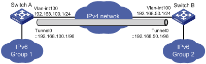
Figure 1-3 Network diagram for an automatic IPv4-compatible IPv6 tunnel
Networking and Configuration Requirements
As shown in Figure 1-3, two IPv6 networks are connected to an IPv4 network through Switch A and Switch B respectively. Configure an automatic IPv4-compatible IPv6 tunnel between Switch A and Switch B to make the two IPv6 networks reachable to each other.
Applicable Product Matrix
|
Product series |
Software version |
Hardware version |
|
S3610 Series Ethernet Switches |
Release 5301, Release 5303 |
All versions |
|
S5510 Series Ethernet Switches |
Release 5301, Release 5303 |
All versions |
Configuration Procedure
![]()
l The corresponding VLAN interfaces have been created on Switch A and Switch B.
l The IP addresses of VLAN-interface 100 on Switch A and Switch B have been configured and an IPv4 route is available between the two interfaces.
l Before enabling IPv6 on an S3610/S5510 series Ethernet switch, you need to configure the device to operate in the IPv4/IPv6 dual-stack mode by using the switch-mode dual-ipv4-ipv6 command. Otherwise, IPv6 packets cannot be forwarded on the device even if IPv6 is enabled. The switch-mode command takes effect after the device is rebooted.
1) Configure Switch A
# Enable IPv6.
<SwitchA> system-view
[SwitchA] ipv6
# Configure an IPv4 address for VLAN-interface 100.
[SwitchA] interface vlan-interface 100
[SwitchA-Vlan-interface100] ip address 192.168.100.1 255.255.255.0
[SwitchA-Vlan-interface100] quit
![]()
For a switch listed in the preceding applicable product matrix in section 1.3.3, its tunnel interface must have a link aggregation group referenced before sending or receiving packets. Make sure that the link aggregation group to be referenced is already created; otherwise, the tunnel interface cannot be up and the switch cannot communicate through the tunnel.
# Configure a link aggregation group. Disable STP on the port before adding it into the link aggregation group.
[SwitchA] link-aggregation group 1 mode manual
[SwitchA] link-aggregation group 1 service-type tunnel
[SwitchA] interface GigabitEthernet 1/0/2
[SwitchA-GigabitEthernet1/0/2] stp disable
[SwitchA-GigabitEthernet1/0/2] port link-aggregation group 1
[SwitchA-GigabitEthernet1/0/2] quit
# Configure an automatic IPv4-compatible IPv6 tunnel.
[SwitchA] interface tunnel 0
[SwitchA-Tunnel0] ipv6 address ::192.168.100.1/96
[SwitchA-Tunnel0] source vlan-interface 100
[SwitchA-Tunnel0] tunnel-protocol ipv6-ipv4 auto-tunnel
# Configure the tunnel to reference link aggregation group 1 in tunnel interface view.
[SwitchA-Tunnel0] aggregation-group 1
2) Configure Switch B
# Enable IPv6.
<SwitchB> system-view
[SwitchB] ipv6
# Configure an IPv4 address for VLAN-interface 100.
[SwitchB] interface vlan-interface 100
[SwitchB-Vlan-interface100] ip address 192.168.50.1 255.255.255.0
[SwitchB-Vlan-interface100] quit
![]()
For a switch listed in the preceding applicable product matrix in section 1.3.3, its tunnel interface must have a link aggregation group referenced before sending or receiving packets. Make sure that the link aggregation group to be referenced is already created; otherwise, the tunnel interface cannot be up and the switch cannot communicate through the tunnel.
# Configure a link aggregation group. Disable STP on the port before adding it into the link aggregation group.
[SwitchB] link-aggregation group 1 mode manual
[SwitchB] link-aggregation group 1 service-type tunnel
[SwitchB] interface GigabitEthernet 1/0/2
[SwitchB-GigabitEthernet1/0/2] stp disable
[SwitchB-GigabitEthernet1/0/2] port link-aggregation group 1
[SwitchB-GigabitEthernet1/0/2] quit
# Configure an automatic IPv4-compatible IPv6 tunnel.
[SwitchB] interface tunnel 0
[SwitchB-Tunnel0] ipv6 address ::192.168.50.1/96
[SwitchB-Tunnel0] source vlan-interface 100
[SwitchB-Tunnel0] tunnel-protocol ipv6-ipv4 auto-tunnel
# Configure the tunnel to reference link aggregation group 1 in tunnel interface view.
[SwitchB-Tunnel0] aggregation-group 1
3) Configuration verification
After the above configurations, display the status of the tunnel interfaces on Switch A and Switch B, respectively.
[SwitchA] display ipv6 interface tunnel 0
[SwitchB] display ipv6 interface tunnel 0
# Ping the IPv4-compatible IPv6 address at the peer end from Switch A.
[SwitchA] ping ipv6 ::192.168.50.1
PING ::192.168.50.1 : 56 data bytes, press CTRL_C to break
Reply from ::192.168.50.1
bytes=56 Sequence=1 hop limit=64 time = 1 ms
Reply from ::192.168.50.1
bytes=56 Sequence=2 hop limit=64 time = 1 ms
Reply from ::192.168.50.1
bytes=56 Sequence=3 hop limit=64 time = 1 ms
Reply from ::192.168.50.1
bytes=56 Sequence=4 hop limit=64 time = 1 ms
Reply from ::192.168.50.1
bytes=56 Sequence=5 hop limit=64 time = 1 ms
--- ::192.168.50.1 ping statistics ---
5 packet(s) transmitted
5 packet(s) received
0.00% packet loss
round-trip min/avg/max = 1/1/1 ms
Complete Configuration
1) Configure Switch A
#
ipv6
#
link-aggregation group 1 mode manual
link-aggregation group 1 service-type tunnel
#
vlan 100
#
interface Vlan-interface100
ip address 192.168.100.1 255.255.255.0
#
interface GigabitEthernet1/0/2
stp disable
port link-aggregation group 1
#
interface Tunnel0
ipv6 address ::192.168.100.1/96
tunnel-protocol ipv6-ipv4 auto-tunnel
source Vlan-interface100
aggregation-group 1
#
2) Configure SwitchB
#
ipv6
#
link-aggregation group 1 mode manual
link-aggregation group 1 service-type tunnel
#
vlan 100
#
interface Vlan-interface100
ip address 192.168.50.1 255.255.255.0
#
interface GigabitEthernet1/0/2
stp disable
port link-aggregation group 1
#
interface Tunnel0
ipv6 address ::192.168.50.1/96
tunnel-protocol ipv6-ipv4 auto-tunnel
source Vlan-interface100
aggregation-group 1
#
Configuration Guidelines
l The same tunnel type should be configured at both ends of the tunnel. Otherwise, packet delivery will fail.
l No destination address needs to be configured for an automatic tunnel.
l The automatic tunnel interfaces using the same encapsulation protocol cannot share the same source IP address.
l If the addresses of the tunnel interfaces at the two ends of a tunnel are not in the same network segment, a forwarding route through the tunnel to the peer must be configured so that the encapsulated packet can be forwarded normally.
l When you configure a static route at one tunnel end, you need to configure a route to the destination IPv6 address of the packet, instead of the IPv4 address of the tunnel destination, and set the outbound interface to the tunnel interface at the local end or set the next-hop to the tunnel interface at the peer end. The similar configuration needs to be performed at the other tunnel end.
l Automatic tunnels do not support dynamic routing.
Configuring Automatic 6to4 Tunnel
An automatic 6to4 tunnel is a point-to-multipoint tunnel and is used to connect multiple isolated IPv6 networks over an IPv4 network to remote IPv6 networks. The embedded IPv4 address in an IPv6 address is used to automatically acquire the destination IPv4 address of the tunnel.
The automatic 6to4 tunnel adopts 6to4 addresses. The address format is 2002:abcd:efgh:subnet number::interface ID/64, where 2002 represents the fixed IPv6 address prefix, and abcd:efgh represents the 32-bit globally unique source IPv4 address of the 6to4 tunnel, in hexadecimal notation. For example, 1.1.1.1 can be represented by 0101:0101. The tunnel destination is automatically determined by the embedded IPv4 address, which makes it easy to create a 6to4 tunnel.
Because the 16-bit subnet number of the 64-bit address prefix in 6to4 addresses can be customized and the first 48 bits in the address prefix are fixed to a permanent value and the IPv4 address of the tunnel source or destination, it is possible that IPv6 packets can be forwarded by the tunnel.
Network Diagram
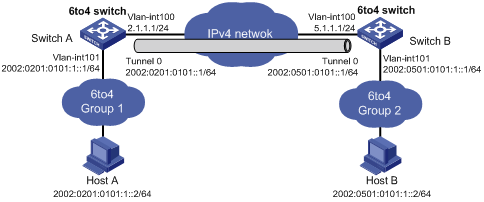
Figure 1-4 Network diagram for an automatic 6to4 tunnel
Networking and Configuration Requirements
As shown in Figure 1-4, two 6to4 networks are connected to an IPv4 network through two 6to4 switches (Switch A and Switch B) respectively. Configure a 6to4 tunnel to make Host A and Host B reachable to each other.
To enable communication between 6to4 networks, you need to configure 6to4 addresses for 6to4 switches and hosts in the 6to4 networks.
l The IPv4 address of VLAN-interface 100 on Switch A is 2.1.1.1/24, and the corresponding 6to4 prefix is 2002:0201:0101::/48 after it is translated to an IPv6 address. Assign interface tunnel 0 to subnet 2002:0201:0101::/64 and VLAN-interface 101 to subnet 2002:0201:0101:1::/64.
l The IPv4 address of VLAN-interface 100 on Switch B is 5.1.1.1/24, and the corresponding 6to4 prefix is 2002:0501:0101::/48 after it is translated to an IPv6 address. Assign interface tunnel 0 to subnet 2002:0501:0101::/64 and VLAN-interface 101 to subnet 2002:0501:0101:1::/64.
Applicable Product Matrix
|
Product series |
Software version |
Hardware version |
|
S3610 Series Ethernet Switches |
Release 5301, Release 5303 |
All versions |
|
S5510 Series Ethernet Switches |
Release 5301, Release 5303 |
All versions |
|
S5500-EI Series Ethernet Switches |
Release 2102 |
All versions |
|
S7500E Series Ethernet Switches |
Release 6100, Release 6300 |
All versions |
Configuration Procedure
![]()
l The corresponding VLAN interfaces have been created on Switch A and Switch B.
l Before enabling IPv6 on an S3610/S5510 series Ethernet switch, you need to configure the device to operate in the IPv4/IPv6 dual-stack mode by using the switch-mode dual-ipv4-ipv6 command. Otherwise, IPv6 packets cannot be forwarded on the device even if IPv6 is enabled. The switch-mode command takes effect after the device is rebooted.
1) Configure Switch A
# Enable IPv6.
<SwitchA> system-view
[SwitchA] ipv6
# Configure an IPv4 address for VLAN-interface 100.
[SwitchA] interface vlan-interface 100
[SwitchA-Vlan-interface100] ip address 2.1.1.1 24
[SwitchA-Vlan-interface100] quit
# Configure an IPv4 address for VLAN-interface 101.
[SwitchA] interface vlan-interface 101
[SwitchA-Vlan-interface101] ipv6 address 2002:0201:0101:1::1/64
[SwitchA-Vlan-interface101] quit
# Configure a link aggregation group or a service loopback group. This configuration depends on the device model.
![]()
l A tunnel interface on an S7500E series Ethernet switch of software version Release 6300 must have a service loopback group referenced before sending or receiving packets. Make sure that the service loopback group to be referenced is already created; otherwise, the tunnel interface cannot be up and the switch cannot communicate through the tunnel.
l For a switch listed in the preceding applicable product matrix in section 1.4.3, except S7500E series Ethernet switches of software version Release 6300, its tunnel interface must have a link aggregation group referenced before sending or receiving packets. Make sure that the link aggregation group to be referenced is already created; otherwise, the tunnel interface cannot be up and the switch cannot communicate through the tunnel.
l Configure a link aggregation group. Note that you need to disable STP on a port before adding it into a link aggregation group.
[SwitchA] link-aggregation group 1 mode manual
[SwitchA] link-aggregation group 1 service-type tunnel
[SwitchA] interface GigabitEthernet 1/0/3
[SwitchA-GigabitEthernet1/0/3] stp disable
[SwitchA-GigabitEthernet1/0/3] port link-aggregation group 1
[SwitchA-GigabitEthernet1/0/3] quit
l Create a service loopback group. Note that you need to disable STP on a port before adding it to a service loopback group.
[SwitchA] service-loopback group 1 type tunnel
[SwitchA] interface GigabitEthernet 1/0/3
[SwitchA-GigabitEthernet1/0/3] stp disable
[SwitchA-GigabitEthernet1/0/3] port service-loopback group 1
[SwitchA-GigabitEthernet1/0/3] quit
# Configure the 6to4 tunnel.
[SwitchA] interface tunnel 0
[SwitchA-Tunnel0] ipv6 address 2002:201:101::1/64
[SwitchA-Tunnel0] source vlan-interface 100
[SwitchA-Tunnel0] tunnel-protocol ipv6-ipv4 6to4
# Configure the tunnel to reference link aggregation group 1 or service loopback group 1 in tunnel interface view. This configuration depends on the device model.
l Configure the tunnel to reference link aggregation group 1 in tunnel interface view.
[SwitchA-Tunnel0] aggregation-group 1
[SwitchA-Tunnel0] quit
l Reference service loopback group 1 in tunnel interface view.
[SwitchA-Tunnel0] service-loopback-group 1
[SwitchA-Tunnel0] quit
# Configure a static route whose destination address is 2002::/16 and next-hop is the tunnel interface.
[SwitchA] ipv6 route-static 2002:: 16 tunnel 0
2) Configure Switch B
# Enable IPv6.
<SwitchB> system-view
[SwitchB] ipv6
# Configure an IPv4 address for VLAN-interface 100.
[SwitchB] interface vlan-interface 100
[SwitchB-Vlan-interface100] ip address 5.1.1.1 24
[SwitchB-Vlan-interface100] quit
# Configure an IPv4 address for VLAN-interface 101.
[SwitchB] interface vlan-interface 101
[SwitchB-Vlan-interface101] ipv6 address 2002:0501:0101:1::1/64
[SwitchB-Vlan-interface101] quit
# Configure a link aggregation group or a service loopback group. This configuration depends on the device model.
![]()
l A tunnel interface on an S7500E series Ethernet switch of software version Release 6300 must have a service loopback group referenced before sending or receiving packets. Make sure that the service loopback group to be referenced is already created; otherwise, the tunnel interface cannot be up and the switch cannot communicate through the tunnel.
l For a switch listed in the preceding applicable product matrix in section 1.4.3, except S7500E series Ethernet switches of software version Release 6300, its tunnel interface must have a link aggregation group referenced before sending or receiving packets. Make sure that the link aggregation group to be referenced is already created; otherwise, the tunnel interface cannot be up and the switch cannot communicate through the tunnel.
l Configure a link aggregation group. Note that you need to disable STP on a port before adding it into a link aggregation group.
[SwitchB] link-aggregation group 1 mode manual
[SwitchB] link-aggregation group 1 service-type tunnel
[SwitchB] interface GigabitEthernet 1/0/3
[SwitchB-GigabitEthernet1/0/3] stp disable
[SwitchB-GigabitEthernet1/0/3] port link-aggregation group 1
[SwitchB-GigabitEthernet1/0/3] quit
l Create a service loopback group. Note that you need to disable STP on a port before adding it to a service loopback group.
[SwitchB] service-loopback group 1 type tunnel
[SwitchB] interface GigabitEthernet 1/0/3
[SwitchB-GigabitEthernet1/0/3] stp disable
[SwitchB-GigabitEthernet1/0/3] port service-loopback group 1
[SwitchB-GigabitEthernet1/0/3] quit
# Configure the 6to4 tunnel.
[SwitchB] interface tunnel 0
[SwitchB-Tunnel0] ipv6 address 2002:0501:0101::1/64
[SwitchB-Tunnel0] source vlan-interface 100
[SwitchB-Tunnel0] tunnel-protocol ipv6-ipv4 6to4
# Configure the tunnel to reference link aggregation group 1 or service loopback group 1 in tunnel interface view. This configuration depends on the device model.
l Configure the tunnel to reference link aggregation group 1 in tunnel interface view.
[SwitchB-Tunnel0] aggregation-group 1
[SwitchB-Tunnel0] quit
l Reference service loopback group 1 in tunnel interface view.
[SwitchB-Tunnel0] service-loopback-group 1
[SwitchB-Tunnel0] quit
# Configure a static route whose destination address is 2002::/16 and next-hop is the tunnel interface.
[SwitchB] ipv6 route-static 2002:: 16 tunnel 0
After the above configuration, ping Host B from Host A or ping Host A from Host B.
D:\>ping6 -s 2002:201:101:1::2 2002:501:101:1::2
Pinging 2002:501:101:1::2
from 2002:201:101:1::2 with 32 bytes of data:
Reply from 2002:501:101:1::2: bytes=32 time=13ms
Reply from 2002:501:101:1::2: bytes=32 time=1ms
Reply from 2002:501:101:1::2: bytes=32 time=1ms
Reply from 2002:501:101:1::2: bytes=32 time<1ms
Ping statistics for 2002:501:101:1::2:
Packets: Sent = 4, Received = 4, Lost = 0 (0% loss),
Approximate round trip times in milli-seconds:
Minimum = 0ms, Maximum = 13ms, Average = 3ms
Complete Configuration
1) Configure Switch A
l Configure the tunnel to reference a link aggregation group on Switch A
#
ipv6
#
link-aggregation group 1 mode manual
link-aggregation group 1 service-type tunnel
#
interface Vlan-interface100
ip address 2.1.1.1 255.255.255.0
#
interface Vlan-interface101
ipv6 address 2002:201:101:1::1/64
#
interface GigabitEthernet1/0/3
stp disable
port link-aggregation group 1
#
interface Tunnel0
ipv6 address 2002:201:101::1/64
tunnel-protocol ipv6-ipv4 6to4
source Vlan-interface100
aggregation-group 1
#
ip route-static 5.1.1.1 255.255.255.0 [nexthop]
#
ipv6 route-static 2002:: 16 Tunnel0
#
l Configure the tunnel to reference a service loopback group on Switch A
#
ipv6
#
service-loopback group 1 type tunnel
#
interface Vlan-interface100
ip address 2.1.1.1 255.255.255.0
#
interface Vlan-interface101
ipv6 address 2002:201:101:1::1/64
#
interface GigabitEthernet1/0/3
stp disable
port service-loopback group 1
#
interface Tunnel0
ipv6 address 2002:201:101::1/64
tunnel-protocol ipv6-ipv4 6to4
source Vlan-interface100
service-loopback-group 1
#
ip route-static 5.1.1.1 255.255.255.0 [nexthop]
#
ipv6 route-static 2002:: 16 Tunnel0
#
2) Configure SwitchB
l Configure the tunnel to reference a link aggregation group on Switch B
#
ipv6
#
link-aggregation group 1 mode manual
link-aggregation group 1 service-type tunnel
#
interface Vlan-interface100
ip address 5.1.1.1 255.255.255.0
#
interface Vlan-interface101
ipv6 address 2002:501:101:1::1/64
#
interface GigabitEthernet1/0/3
stp disable
port link-aggregation group 1
#
interface Tunnel0
ipv6 address 2002:501:101::1/64
tunnel-protocol ipv6-ipv4 6to4
source Vlan-interface100
aggregation-group 1
#
ip route-static 2.1.1.1 255.255.255.0 [nexthop]
#
ipv6 route-static 2002:: 16 Tunnel0
#
l Configure the tunnel to reference a service loopback group on Switch B
#
ipv6
#
service-loopback group 1 type tunnel
#
interface Vlan-interface100
ip address 5.1.1.1 255.255.255.0
#
interface Vlan-interface101
ipv6 address 2002:501:101:1::1/64
#
interface GigabitEthernet1/0/3
stp disable
port service-loopback group 1
#
interface Tunnel0
ipv6 address 2002:501:101::1/64
tunnel-protocol ipv6-ipv4 6to4
source Vlan-interface100
service-loopback-group 1
#
ip route-static 2.1.1.1 255.255.255.0 [nexthop]
#
ipv6 route-static 2002:: 16 Tunnel0
#
Configuration Guidelines
l The same tunnel type should be configured at both ends of the tunnel. Otherwise, packet delivery will fail.
l No destination address needs to be configured for an automatic tunnel.
l The automatic tunnel interfaces using the same encapsulation protocol cannot share the same source IP address.
l For a distributed device (such as S7500E series), a tunnel interface number is in the A/B/C format, where A, B, and C represent the slot number of a card, the slot number of a sub-card, and the tunnel interface number, respectively.
l When you create a tunnel interface on a distributed device (such as S7500E series), the slot of the tunnel interface is recommended to be that of the source interface, namely, the interface sending packets. In this way, the forwarding efficiency can be improved.
l For a distributed device (such as S7500E series), the tunnel configuration is not removed from the active board upon switchover or from the standby board upon its removal. If you configure the same tunnel, the system will display the prompt that the tunnel still exists. To delete the tunnel interface, use the undo interface tunnel command.
l If the addresses of the tunnel interfaces at the two ends of a tunnel are not in the same network segment, a forwarding route through the tunnel to the peer must be configured so that the encapsulated packet can be forwarded normally.
l When you configure a static route at one tunnel end, you need to configure a route to the destination IPv6 address of the packet, instead of the IPv4 address of the tunnel destination, and set the outbound interface to the tunnel interface at the local end or set the next-hop to the tunnel interface at the peer end. The similar configuration needs to be performed at the other tunnel end.
l Automatic tunnels do not support dynamic routing.
Configuring ISATAP Tunnel
An ISATAP tunnel is a point-to-point automatic tunnel. The destination of a tunnel can automatically be acquired from the embedded IPv4 address in the destination address of an IPv6 packet.
When an ISATAP tunnel is used, the destination address of an IPv6 packet and the IPv6 address of a tunnel interface both adopt special ISATAP addresses. The ISATAP address format is prefix(64bit):0:5EFE:ip-address. The 64-bit prefix is the prefix of a valid IPv6 unicast address, while ip-address is a 32-bit source IPv4 address in the form of a.b.c.d or abcd:efgh, which need not be globally unique. Through the embedded IPv4 address, an ISATAP tunnel can automatically be created to transfer IPv6 packets.
The ISATAP tunnel is mainly used for connection between IPv6 routers or between a host and an IPv6 router over an IPv4 network.
Network Diagram
Figure 1-5 Network diagram for an ISATAP tunnel
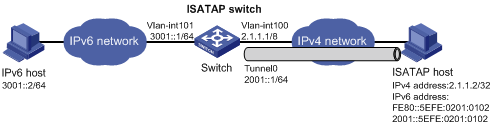
Networking and Configuration Requirements
As shown in Figure 1-5, an IPv6 network is connected to an IPv4 network through an ISATAP switch. The destination address of the tunnel is an ISATAP address. It is required that IPv6 hosts in the IPv4 network can access the IPv6 network through the ISATAP tunnel.
Applicable Product Matrix
|
Product series |
Software version |
Hardware version |
|
S3610 Series Ethernet Switches |
Release 5301, Release 5303 |
All versions |
|
S5510 Series Ethernet Switches |
Release 5301, Release 5303 |
All versions |
|
S5500-EI Series Ethernet Switches |
Release 2102 |
All versions |
|
S7500E Series Ethernet Switches |
Release 6100, Release 6300 |
All versions |
Configuration Procedure
![]()
l The corresponding VLAN interfaces have been created on Switch.
l The IP addresses of ISATAP host and VLAN-interface 101 on Switch have been configured and an IPv4 route is available between them.
l Before enabling IPv6 on an S3610/S5510 series Ethernet switch, you need to configure the device to operate in the IPv4/IPv6 dual-stack mode by using the switch-mode dual-ipv4-ipv6 command. Otherwise, IPv6 packets cannot be forwarded on the device even if IPv6 is enabled. The switch-mode command takes effect after the device is rebooted.
1) Configure Switch
# Enable IPv6.
<Switch> system-view
[Switch] ipv6
# Configure addresses for interfaces.
[Switch] interface vlan-interface 100
[Switch-Vlan-interface100] ipv6 address 3001::1/64
[Switch-Vlan-interface100] quit
[Switch] interface vlan-interface 101
[Switch-Vlan-interface101] ip address 2.1.1.1 255.0.0.0
[Switch-Vlan-interface101] quit
# Configure a link aggregation group or a service loopback group. This configuration depends on the device model.
![]()
l A tunnel interface on an S7500E series Ethernet switch of software version Release 6300 must have a service loopback group referenced before sending or receiving packets. Make sure that the service loopback group to be referenced is already created; otherwise, the tunnel interface cannot be up and the switch cannot communicate through the tunnel.
l For a switch listed in the preceding applicable product matrix in section 1.5.3, except S7500E series Ethernet switches of software version Release 6300, its tunnel interface must have a link aggregation group referenced before sending or receiving packets. Make sure that the link aggregation group to be referenced is already created; otherwise, the tunnel interface cannot be up and the switch cannot communicate through the tunnel.
l Configure a link aggregation group. Note that you need to disable STP on a port before adding it into a link aggregation group.
[Switch] link-aggregation group 1 mode manual
[Switch] link-aggregation group 1 service-type tunnel
[Switch] interface GigabitEthernet 1/0/3
[Switch-GigabitEthernet1/0/3] stp disable
[Switch-GigabitEthernet1/0/3] port link-aggregation group 1
[Switch-GigabitEthernet1/0/3] quit
l Create a service loopback group. Note that you need to disable STP on a port before adding it to a service loopback group.
[Switch] service-loopback group 1 type tunnel
[Switch] interface GigabitEthernet 1/0/3
[Switch-GigabitEthernet1/0/3] stp disable
[Switch-GigabitEthernet1/0/3] port service-loopback group 1
[Switch-GigabitEthernet1/0/3] quit
# Configure an ISATAP tunnel.
[Switch] interface tunnel 0
[Switch-Tunnel0] ipv6 address 2001::1/64 eui-64
[Switch-Tunnel0] source vlan-interface 101
[Switch-Tunnel0] tunnel-protocol ipv6-ipv4 isatap
# Configure the tunnel to reference link aggregation group 1 or service loopback group 1 in tunnel interface view. This configuration depends on the device model.
l Configure the tunnel to reference link aggregation group 1 in tunnel interface view.
[Switch-Tunnel0] aggregation-group 1
l Reference service loopback group 1 in tunnel interface view.
[Switch-Tunnel0] service-loopback-group 1
# Disable the RA suppression so that hosts can acquire information such as the address prefix from the RA message released by the ISATAP switch.
[Switch-Tunnel0] undo ipv6 nd ra halt
[Switch-Tunnel0] quit
# Configure a static route to the ISATAP host.
[Switch] ipv6 route-static 2001:: 16 tunnel 0
2) Configure the ISATAP host
The specific configuration on the ISATAP host is related to its operating system. The following example shows the configuration of the host running the Windows XP.
# On a Windows XP-based host, the ISATAP interface is usually interface 2. Configure the IPv4 address of the ISATAP switch on the interface to complete the configuration on the host. Before doing that, display the ISATAP interface information:
C:\>ipv6 if 2
Interface 2: Automatic Tunneling Pseudo-Interface
Guid {48FCE3FC-EC30-E50E-F1A7-71172AEEE3AE}
does not use Neighbor Discovery
does not use Router Discovery
routing preference 1
EUI-64 embedded IPv4 address: 0.0.0.0
router link-layer address: 0.0.0.0
preferred link-local fe80::5efe:2.1.1.2, life infinite
link MTU 1280 (true link MTU 65515)
current hop limit 128
reachable time 42500ms (base 30000ms)
retransmission interval 1000ms
DAD transmits 0
default site prefix length 48
# A link-local address (fe80::5efe:2.1.1.2) in the ISATAP format was automatically generated for the ISATAP interface. Configure the IPv4 address of the ISATAP switch on the ISATAP interface.
C:\>ipv6 rlu 2 2.1.1.1
# After carrying out the above command, look at the information on the ISATAP interface.
C:\>ipv6 if 2
Interface 2: Automatic Tunneling Pseudo-Interface
Guid {48FCE3FC-EC30-E50E-F1A7-71172AEEE3AE}
does not use Neighbor Discovery
uses Router Discovery
routing preference 1
EUI-64 embedded IPv4 address: 2.1.1.2
router link-layer address: 2.1.1.1
preferred global 2001::5efe:2.1.1.2, life 29d23h59m46s/6d23h59m46s (public)
preferred link-local fe80::5efe:2.1.1.2, life infinite
link MTU 1500 (true link MTU 65515)
current hop limit 255
reachable time 42500ms (base 30000ms)
retransmission interval 1000ms
DAD transmits 0
default site prefix length 48
# By comparison, it is found that the host acquires the address prefix 2001::/64 and automatically generates the address 2001::5efe:2.1.1.2. Meanwhile, “uses Router Discovery” is displayed, indicating that the router discovery function is enabled on the host. At this time, ping the IPv6 address of the tunnel interface of the switch. If the address is successfully pinged, an ISATAP tunnel is established.
Complete Configuration
l Configure the tunnel to reference a link aggregation group on Switch
#
ipv6
#
link-aggregation group 1 mode manual
link-aggregation group 1 service-type tunnel
#
interface Vlan-interface100
ipv6 address 3001::1/64
#
interface Vlan-interface101
ip address 2.1.1.1 255.0.0.0
#
interface GigabitEthernet1/0/3
stp disable
port link-aggregation group 1
#
interface Tunnel0
ipv6 address 2001::1/64 eui-64
undo ipv6 nd ra halt
tunnel-protocol ipv6-ipv4 isatap
source Vlan-interface101
aggregation-group 1
#
ipv6 route-static 2001:: 16 tunnel 0
#
l Configure the tunnel to reference a service loopback group on Switch
#
ipv6
#
service-loopback group 1 type tunnel
#
interface Vlan-interface100
ipv6 address 3001::1/64
#
interface Vlan-interface101
ip address 2.1.1.1 255.0.0.0
#
interface GigabitEthernet1/0/3
stp disable
port service-loopback group 1
#
interface Tunnel0
ipv6 address 2001::1/64 eui-64
undo ipv6 nd ra halt
tunnel-protocol ipv6-ipv4 isatap
source Vlan-interface101
service-loopback-group 1
#
ipv6 route-static 2001:: 16 tunnel 0
#
Configuration Guidelines
l The automatic tunnel interfaces using the same encapsulation protocol cannot share the same source IP address.
l For a distributed device (such as S7500E series), a tunnel interface number is in the A/B/C format, where A, B, and C represent the slot number of a card, the slot number of a sub-card, and the tunnel interface number, respectively.
l When you create a tunnel interface on a distributed device (such as S7500E series), the slot of the tunnel interface is recommended to be that of the source interface, namely, the interface sending packets. In this way, the forwarding efficiency can be improved.
l For a distributed device (such as S7500E series), the tunnel configuration is not removed from the active board upon switchover or from the standby board upon its removal. If you configure the same tunnel, the system will display the prompt that the tunnel still exists. To delete the tunnel interface, use the undo interface tunnel command.
l If the addresses of the tunnel interfaces at the two ends of a tunnel are not in the same network segment, a forwarding route through the tunnel to the peer must be configured so that the encapsulated packet can be forwarded normally.
l When you configure a static route at one tunnel end, you need to configure a route to the destination IPv6 address of the packet, instead of the IPv4 address of the tunnel destination, and set the outbound interface to the tunnel interface at the local end or set the next-hop to the tunnel interface at the peer end. The similar configuration needs to be performed at the other tunnel end.
l Automatic tunnels do not support dynamic routing.