- Table of Contents
-
- H3C Low-End and Mid-Range Ethernet Switches Configuration Examples(V1.01)
- 00-1Cover
- 01-Login Configuration Guide
- 02-VLAN Configuration Guide
- 03-GVRP Configuration Guide
- 04-Voice VLAN Configuration Guide
- 05-IP Addressing and Performance Configuration Guide
- 06-QinQ Configuration Guide
- 07-BPDU Tunnel Configuration Guide
- 08-VLAN Mapping Configuration Guide
- 09-MAC Address Table Management Configuration Guide
- 10-Link Aggregation Configuration Guide
- 11-IP Source Guard Configuration Guide
- 12-DLDP Configuration Guide
- 13-MSTP Configuration Guide
- 14-IPv4 Routing Configuration Guide
- 15-IPv6 Configuration Guide
- 16-IPv6 Routing Configuration Guide
- 17-IPv4 Multicast Configuration Guide
- 18-IPv6 Multicast Configuration Examples
- 19-802.1x Configuration Guide
- 20-AAA Configuration Guide
- 21-MAC Authentication Configuration Guide
- 22-Portal Configuration Guide
- 23-ARP Configuration Guide
- 24-DHCP Configuration Guide
- 25-ACL Configuration Guide
- 26-QoS Configuration Guide
- 27-Port Mirroring Configuration Guide
- 28-Cluster Management Configuration Guide
- 29-SNMP-RMON Configuration Guide
- 30-NTP Configuration Guide
- 31-FTP-TFTP Configuration Guide
- 32-UDP Helper Configuration Guide
- 33-Information Center Configuration Guide
- 34-DNS Configuration Guide
- 35-File System Management Configuration Guide
- 36-Remote Upgrade Configuration Guide
- 37-NQA Configuration Guide
- 38-VRRP Configuration Guide
- 39-SSH Configuration Guide
- 40-Port Security Configuration Guide
- 41-Port Isolation Configuration Guide
- 42-LLDP Configuration Guide
- 43-MCE Configuration Guide
- 44-PoE Configuration Guide
- 45-OAM Configuration Guide
- 46-Connectivity Fault Detection Configuration Guide
- 47-RRPP Configuration Guide
- 48-sFlow Configuration Guide
- 49-SSL-HTTPS Configuration Guide
- 50-PKI Configuration Guide
- 51-Track Configuration Guide
- 52-EPON-OLT Configuration Guide
- 53-Smart Link Configuration Guide
- 54-MPLS Configuration Guide
- Related Documents
-
| Title | Size | Download |
|---|---|---|
| 17-IPv4 Multicast Configuration Guide | 617.86 KB |
Table of Contents
1 Multicast Configuration Guide
Configuring Basic IGMP Functions
IGMP Snooping Configuration Examples
Configuring Group Policy and Simulated Joining
Configuring IGMP Snooping Querier
Multicast VLAN Configuration Examples
Configuring Sub-VLAN-Based IPv4 Multicast VLAN
Configuring Port-Based IPv4 Multicast VLAN
Configuring PIM-SM Non-Scoped Zone
Configuring PIM-SM Administratively Scoped Zone
Configuring Inter-Domain Multicast Leveraging BGP Routes
Configuring Inter-Domain Multicast Leveraging Static RPF Peers
Multicast Routing and Forwarding Configuration Example
IGMP Configuration Examples
Configuring Basic IGMP Functions
Network diagram
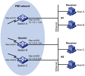
Figure 1-1 Network diagram for basic IGMP functions configuration (on switches)
Network requirements
l Receivers receive VOD information through multicast. Receivers of different organizations form stub networks N1 and N2, and Host A and Host C are receivers in N1 and N2 respectively.
l Switch A in the PIM network connects to N1, and both Switch B and Switch C connect to N2.
l Switch A connects to N1 through VLAN-interface 100, and to other devices in the PIM network through VLAN-interface 101.
l Switch B and Switch C connect to N2 through their respective VLAN-interface 200, and to other devices in the PIM network through VLAN-interface 201 and VLAN-interface 202 respectively.
l IGMPv2 is required between Switch A and N1. IGMPv2 is also required between the other two switches and N2, Switch B serves as the IGMP querier in N2 because its IP address is lower.
l On Switch A, specify the IGMP query interval to 30 seconds, the maximum response time to 5 seconds, and the IGMP last member query interval to 2 seconds.
Applicable product matrix
|
Product series |
Software version |
Hardware version |
|
S3610 Series Ethernet Switches |
Release 5301, Release 5303 |
All versions |
|
S5510 Series Ethernet Switches |
Release 5301, Release 5303 |
All versions |
|
S5500-EI Series Ethernet Switches |
Release 2102 |
All versions |
|
S7500E Series Ethernet Switches |
Release 6100, Release 6300 |
All versions |
Configuration procedure
1) Configure IP addresses and unicast routing
Configure the IP address and subnet mask of each interface as per Figure 1-1_Ref142231221. The detailed configuration steps are omitted here.
Configure the OSPF protocol for interoperation on the PIM network. Ensure the network-layer interoperation on the PIM network and dynamic update of routing information among the switches through a unicast routing protocol. The detailed configuration steps are omitted here.
2) Enable IP multicast routing, and enable PIM-DM and IGMP
# Enable IP multicast routing on Switch A, enable PIM-DM on each interface, and enable IGMP on VLAN-interface 100.
<SwitchA> system-view
[SwitchA] multicast routing-enable
[SwitchA] interface vlan-interface 100
[SwitchA-Vlan-interface100] igmp enable
[SwitchA-Vlan-interface100] pim dm
[SwitchA-Vlan-interface100] quit
[SwitchA] interface vlan-interface 101
[SwitchA-Vlan-interface101] pim dm
[SwitchA-Vlan-interface101] quit
# Enable IP multicast routing on Switch B, enable PIM-DM on each interface, and enable IGMP on VLAN-interface 200.
<SwitchB> system-view
[SwitchB] multicast routing-enable
[SwitchB] interface vlan-interface 200
[SwitchB-Vlan-interface200] igmp enable
[SwitchB-Vlan-interface200] pim dm
[SwitchB-Vlan-interface200] quit
[SwitchB] interface vlan-interface 201
[SwitchB-Vlan-interface201] pim dm
[SwitchB-Vlan-interface201] quit
# Enable IP multicast routing on Switch C, enable PIM-DM on each interface, and enable IGMP on VLAN-interface 200.
<SwitchC> system-view
[SwitchC] multicast routing-enable
[SwitchC] interface vlan-interface 200
[SwitchC-Vlan-interface200] igmp enable
[SwitchC-Vlan-interface200] pim dm
[SwitchC-Vlan-interface200] quit
[SwitchC] interface vlan-interface 202
[SwitchC-Vlan-interface202] pim dm
[SwitchC-Vlan-interface202] quit
3) Verify the configuration
Carry out the display igmp interface command to view the IGMP configuration and operation status on each switch interface. For example:
# View IGMP information on VLAN-interface 200 of Switch B.
[SwitchB] display igmp interface vlan-interface 200
Vlan-interface200(10.110.2.1):
IGMP is enabled
Current IGMP version is 2
Value of query interval for IGMP(in seconds): 60
Value of other querier present interval for IGMP(in seconds): 125
Value of maximum query response time for IGMP(in seconds): 10
Querier for IGMP: 10.110.2.1 (this router)
Total 1 IGMP Group reported
Complete configuration
1) Configuration on SwitchA
#
multicast routing-enable
#
vlan 100 to 101
#
interface Vlan-interface100
igmp enable
igmp timer query 30
igmp max-response-time 5
igmp last-member-query-interval 2
pim dm
#
interface Vlan-interface101
pim dm
The configuration on Switch B and Switch C is similar to the configuration on Switch A.,
Configuration guidelines
l Make sure that the IGMP query interval is greater than the maximum response time for IGMP general queries; otherwise, multicast group members may be wrongly removed.
l The configurations of the maximum response time for IGMP general queries, the IGMP last member query interval and the IGMP other querier present interval are effective only for IGMPv2 or IGMPv3.
Configuring IGMP SSM Mapping
Network diagram
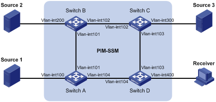
Figure 1-2 Network diagram for IGMP SSM mapping configuration (on switches)
|
Device |
Interface |
IP address |
Device |
Interface |
IP address |
|
Source 1 |
— |
133.133.1.1/24 |
Source 3 |
— |
133.133.3.1/24 |
|
Source 2 |
— |
133.133.2.1/24 |
Receiver |
— |
133.133.4.1/24 |
|
Switch A |
Vlan-int100 |
133.133.1.2/24 |
Switch C |
Vlan-int300 |
133.133.3.2/24 |
|
|
Vlan-int101 |
192.168.1.1/24 |
|
Vlan-int103 |
192.168.3.1/24 |
|
|
Vlan-int104 |
192.168.4.2/24 |
|
Vlan-int102 |
192.168.2.2/24 |
|
Switch B |
Vlan-int200 |
133.133.2.2/24 |
Switch D |
Vlan-int400 |
133.133.4.2/24 |
|
|
Vlan-int101 |
192.168.1.2/24 |
|
Vlan-int103 |
192.168.3.2/24 |
|
|
Vlan-int102 |
192.168.2.1/24 |
|
Vlan-int104 |
192.168.4.1/24 |
Network requirements
l On the PIM-SSM network shown in Figure 1-2, the receiver host receives VOD information through multicast. The receiver host runs IGMPv2, so it cannot specify the expected multicast sources in its membership reports.
l The receiver host joins a multicast group in the range of 232.1.1.0/24.
l It is required to configure the IGMP SSM mapping feature on Switch D so that the receiver host will receive multicast data from Source 1 and Source 3 only.
Applicable product matrix
|
Product series |
Software version |
Hardware version |
|
S7500E Series Ethernet Switches |
Release 6100, Release 6300 |
All versions |
Configuration procedure
1) Configure IP addresses and unicast routing
Configure the IP address and subnet mask of each interface as per Figure 1-2. The detailed configuration steps are omitted here.
Configure OSPF for interoperability among the switches. Ensure the network-layer interoperation on the PIM-SSM network and dynamic update of routing information among the switches through a unicast routing protocol. The detailed configuration steps are omitted here.
2) Enable IP multicast routing, enable PIM-SM on each interface, and enable IGMP and IGMP SSM mapping on the host-side interface.
# Enable IP multicast routing on Switch D, enable PIM-SM on each interface, and enable IGMPv3 and IGMP SSM mapping on VLAN-interface 400.
<SwitchD> system-view
[SwitchD] multicast routing-enable
[SwitchD] interface vlan-interface 400
[SwitchD-Vlan-interface400] igmp enable
[SwitchD-Vlan-interface400] igmp version 3
[SwitchD-Vlan-interface400] igmp ssm-mapping enable
[SwitchD-Vlan-interface400] pim sm
[SwitchD-Vlan-interface400] quit
[SwitchD] interface vlan-interface 103
[SwitchD-Vlan-interface103] pim sm
[SwitchD-Vlan-interface103] quit
[SwitchD] interface vlan-interface 104
[SwitchD-Vlan-interface104] pim sm
[SwitchD-Vlan-interface104] quit
# Enable IP multicast routing on Switch A, and enable PIM-SM on each interface.
<SwitchA> system-view
[SwitchA] multicast routing-enable
[SwitchA] interface vlan-interface 100
[SwitchA-Vlan-interface100] pim sm
[SwitchA-Vlan-interface100] quit
[SwitchA] interface vlan-interface 101
[SwitchA-Vlan-interface101] pim sm
[SwitchA-Vlan-interface101] quit
[SwitchA] interface vlan-interface 104
[SwitchA-Vlan-interface104] pim sm
[SwitchA-Vlan-interface104] quit
The configuration on Switch B and Switch C is similar to that on Switch A.
3) Configure a C-BSR and a C-RP
# Configure C-BSR and C-RP interfaces on Switch D.
[SwitchD] pim
[SwitchD-pim] c-bsr vlan-interface 104
[SwitchD-pim] c-rp vlan-interface 104
[SwitchD-pim] quit
4) Configure the SSM group range
# Configure the SSM group range 232.1.1.0/24 on Switch D.
[SwitchD] acl number 2000
[SwitchD-acl-basic-2000] rule permit source 232.1.1.0 0.0.0.255
[SwitchD-acl-basic-2000] quit
[SwitchD] pim
[SwitchD-pim] ssm-policy 2000
[SwitchD-pim] quit
The configuration on Switch A, Switch B and Switch C is similar to that on Switch D.
5) Configure IGMP SSM mappings
# Configure IGMP SSM mappings on Switch D.
[SwitchD] igmp
[SwitchD-igmp] ssm-mapping 232.1.1.1 24 133.133.1.1
[SwitchD-igmp] ssm-mapping 232.1.1.1 24 133.133.3.1
[SwitchD-igmp] quit
6) Verify the configuration
Use the display igmp ssm-mapping command to view the IGMP SSM mappings on the switch.
# View the IGMP SSM mapping information for multicast group 232.1.1.1 on Switch D.
[SwitchD] display igmp ssm-mapping 232.1.1.1
Group address: 232.1.1.1
Source list: 133.133.1.1
133.133.3.1
Use the display igmp ssm-mapping group command to view the multicast group information created based on the configured IGMP SSM mappings.
# View the IGMP multicast group information created based on the IGMP SSM mappings on Switch D.
[SwitchD] display igmp ssm-mapping group
Total 1 IGMP SSM-mapping Group(s).
Interface group report information of VPN-Instance: public net
Vlan-interface400(133.133.4.2):
Total 1 IGMP SSM-mapping Group reported
Group Address Last Reporter Uptime Expires
232.1.1.1 133.133.4.1 00:02:04 off
Use the display pim routing-table command to view the PIM routing table information on each switch.
# View the PIM routing table information on Switch D.
[SwitchD] display pim routing-table
Total 0 (*, G) entry; 2 (S, G) entry
(133.133.1.1, 232.1.1.1)
Protocol: pim-ssm, Flag:
UpTime: 00:13:25
Upstream interface: Vlan-interface104
Upstream neighbor: 192.168.4.2
RPF prime neighbor: 192.168.4.2
Downstream interface(s) information:
Total number of downstreams: 1
1: Vlan-interface400
Protocol: igmp, UpTime: 00:13:25, Expires: -
(133.133.3.1, 232.1.1.1)
Protocol: pim-ssm, Flag:
UpTime: 00:13:25
Upstream interface: Vlan-interface103
Upstream neighbor: 192.168.3.1
RPF prime neighbor: 192.168.3.1
Downstream interface(s) information:
Total number of downstreams: 1
1: Vlan-interface400
Protocol: igmp, UpTime: 00:13:25, Expires: -
Complete configuration
l Configuration on SwitchD
#
multicast routing-enable
#
acl number 2000
rule 0 permit source 232.1.1.0 0.0.0.255
#
vlan 103 to 104
#
vlan 400
#
interface Vlan-interface103
pim sm
#
interface Vlan-interface104
pim sm
#
interface Vlan-interface400
igmp enable
igmp version 3
igmp ssm-mapping enable
#
igmp
ssm-mapping 232.1.1.0 24 133.133.1.1
ssm-mapping 232.1.1.0 24 133.133.3.1
#
pim
c-bsr Vlan-interface104
c-rp Vlan-interface104
ssm-policy 2000
l Configuration on SwitchA
#
multicast routing-enable
#
acl number 2000
rule 0 permit source 232.1.1.0 0.0.0.255
#
vlan 100 to 101
#
vlan 104
#
interface Vlan-interface100
pim sm
#
interface Vlan-interface101
pim sm
#
interface Vlan-interface101
pim sm
The configuration on Switch B and Switch C is similar to the configuration on Switch A.,
Configuration guidelines
l To ensure SSM service for all hosts on a subnet, regardless of the IGMP version running on the hosts, enable IGMPv3 on the interface that forwards multicast traffic onto the subnet.
l If IGMPv3 is enabled on a VLAN interface of a switch that supports both IGMP Snooping and IGMP, and if a port in that VLAN is configured as a simulated host, the simulated host will send IGMPv3 reports even if you did not specify a multicast source when configuring simulated joining with the igmp-snooping host-join command. In this case, the corresponding multicast group will not be created based on the configured IGMP SSM mappings.
IGMP Snooping Configuration Examples
Configuring Group Policy and Simulated Joining
Network diagram
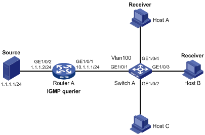
Figure 1-3 Network diagram for simulated joining configuration
Networking and configuration requirements
l As shown in Figure 1-3, Router A connects to the multicast source through GigabitEthernet 1/0/2 and to Switch A through GigabitEthernet 1/0/1.
l IGMPv2 is required on Router A, IGMP Snooping version 2 is required on Switch A, and Router A will act as the IGMP querier on the subnet.
l It is required that the receivers, Host A and Host B, attached to Switch A can receive multicast traffic addressed to multicast group 224.1.1.1 only.
l It is required that multicast data for group 224.1.1.1 can be forwarded through GigabitEthernet 1/0/3 and GigabitEthernet 1/0/4 of Switch A even if Host A and Host B accidentally, temporarily stop receiving multicast data.
Applicable product matrix
|
Product |
Software version |
Hardware version |
|
S3610 Series Ethernet Switches |
Release 5301, Release 5303 |
All versions |
|
S5510 Series Ethernet Switches |
Release 5301, Release 5303 |
All versions |
|
S5500-SI Series Ethernet Switches |
Release 1207 |
All versions (except S5500-20TP-SI) |
|
Release 1301 |
S5500-20TP-SI |
|
|
S5500-EI Series Ethernet Switches |
Release 2102 |
All versions |
|
S7500E Series Ethernet Switches |
Release 6100, Release 6300 |
All versions |
Configuration procedure
Configure an IP address and subnet mask for each interface as per Figure 1-3. The detailed configuration steps are omitted.
2) Configure Router A
# Enable IP multicast routing, enable PIM-DM on each interface, and enable IGMPv2 on GigabitEthernet 1/0/1.
<RouterA> system-view
[RouterA] multicast routing-enable
[RouterA] interface GigabitEthernet 1/0/1
[RouterA-GigabitEthernet1/0/1] igmp enable
[RouterA-GigabitEthernet1/0/1] pim dm
[RouterA-GigabitEthernet1/0/1] quit
[RouterA] interface GigabitEthernet 1/0/2
[RouterA-GigabitEthernet1/0/2] pim dm
[RouterA-GigabitEthernet1/0/2] quit
3) Configure Switch A
# Enable IGMP Snooping globally.
<SwitchA> system-view
[SwitchA] igmp-snooping
[SwitchA-igmp-snooping] quit
# Create VLAN 100, assign GigabitEthernet 1/0/1 through GigabitEthernet 1/0/4 to this VLAN, and enable IGMP Snooping and the function of dropping unknown multicast traffic in the VLAN.
[SwitchA] vlan 100
[SwitchA-vlan100] port GigabitEthernet 1/0/1 to GigabitEthernet 1/0/4
[SwitchA-vlan100] igmp-snooping enable
[SwitchA-vlan100] igmp-snooping drop-unknown
[SwitchA-vlan100] quit
# Configure a multicast group filter so that the hosts in VLAN 100 can join only the multicast group 224.1.1.1.
[SwitchA] acl number 2001
[SwitchA-acl-basic-2001] rule permit source 224.1.1.1 0
[SwitchA-acl-basic-2001] quit
[SwitchA] igmp-snooping
[SwitchA-igmp-snooping] group-policy 2001 vlan 100
[SwitchA-igmp-snooping] quit
# Enable simulated host joining on GigabitEthernet 1/0/3 and GigabitEthernet 1/0/4 respectively.
[SwitchA] interface GigabitEthernet 1/0/3
[SwitchA-GigabitEthernet1/0/3] igmp-snooping host-join 224.1.1.1 vlan 100
[SwitchA-GigabitEthernet1/0/3] quit
[SwitchA] interface GigabitEthernet 1/0/4
[SwitchA-GigabitEthernet1/0/4] igmp-snooping host-join 224.1.1.1 vlan 100
[SwitchA-GigabitEthernet1/0/4] quit
4) Verify the configuration
# View the detailed information about IGMP Snooping multicast groups in VLAN 100 on Switch A.
[SwitchA] display igmp-snooping group vlan 100 verbose
Total 1 IP Group(s).
Total 1 IP Source(s).
Total 1 MAC Group(s).
Port flags: D-Dynamic port, S-Static port, A-Aggregation port, C-Copy port
Subvlan flags: R-Real VLAN, C-Copy VLAN
Vlan(id):100.
Total 1 IP Group(s).
Total 1 IP Source(s).
Total 1 MAC Group(s).
Router port(s):total 1 port.
GE1/0/1 (D) ( 00:01:30 )
IP group(s):the following ip group(s) match to one mac group.
IP group address:224.1.1.1
(0.0.0.0, 224.1.1.1):
Attribute: Host Port
Host port(s):total 2 port.
GE1/0/3 (D) ( 00:03:23 )
GE1/0/4 (D) ( 00:03:23 )
MAC group(s):
MAC group address:0100-5e01-0101
Host port(s):total 2 port.
GE1/0/3
GE1/0/4
As shown above, GigabitEthernet 1/0/3 and GigabitEthernet 1/0/4 of Switch A have joined multicast group 224.1.1.1.
Complete configuration
1) Configuration on Switch A
#
acl number 2001
rule 0 permit source 224.1.1.1 0
#
igmp-snooping
group-policy 2001 vlan 100
#
vlan 100
igmp-snooping enable
igmp-snooping drop-unknown
#
interface GigabitEthernet1/0/1
port access vlan 100
#
interface GigabitEthernet1/0/2
port access vlan 100
#
interface GigabitEthernet1/0/3
port access vlan 100
igmp-snooping host-join 224.1.1.1 vlan 1
#
interface GigabitEthernet1/0/4
port access vlan 100
igmp-snooping host-join 224.1.1.1 vlan 1
#
Configuration guidelines
l Layer 2 and Layer 3 multicast protocols can run simultaneously on a switch, but a Layer 2 multicast protocol cannot run in a VLAN while a Layer 3 multicast protocol is running on the virtual interface of that VLAN, and vice versa.
l IGMP Snooping must be enabled globally in system view before it can be enabled in a VLAN.
l Unlike a static member port, a port configured as a simulated member host will age out like a dynamic member port.
l Unknown IPv6 multicast packets are discarded if you enable the function of dropping unknown IPv4 multicast packets.
Configuring Static Ports
Network diagram
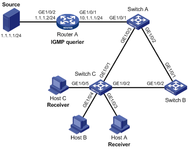
Figure 1-4 Network diagram for static router port configuration
Networking and configuration requirements
l If receivers are steady on receiving the multicast data addressed to a particular group, you can configure a static port to enhance the reliability of multicast data transmission.
l As shown in Figure 1-4, Router A connects to a multicast source (Source) through GigabitEthernet 1/0/2, and to Switch A through GigabitEthernet 1/0/1.
l IGMP is to run between Router A and Switch A, and IGMP Snooping is to run on Switch A, Switch B and Switch C, with Router A acting as the IGMP querier.
l Suppose STP runs on the network. To avoid data loops, the forwarding path from Switch A to Switch C is blocked under normal conditions, and multicast traffic flows to the receivers, Host A and Host C, attached to Switch C only along the path of Switch A—Switch B—Switch C.
l Now it is required to configure GigabitEthernet 1/0/3 that connects Switch A to Switch C as a static router port, so that multicast traffic can flow to the receivers nearly uninterruptedly along the path of Switch A—Switch C in the case that the path of Switch A—Switch B—Switch C gets blocked.
l It is required to configure GigabitEthernet 1/0/3 and GigabitEthernet 1/0/5 on Switch C as static member ports for multicast group 225.1.1.1, so that the attached two receivers can steadily receive multicast data destined for that multicast group.
![]()
If no static router port is configured, when the path of Switch A—Switch B—Switch C gets blocked, at least one IGMP query-response cycle must be completed before the multicast data can flow to the receivers along the new path of Switch A—Switch C, namely multicast delivery will be interrupted during this process.
Applicable product matrix
|
Product |
Software version |
Hardware version |
|
S3610 Series Ethernet Switches |
Release 5301, Release 5303 |
All versions |
|
S5510 Series Ethernet Switches |
Release 5301, Release 5303 |
All versions |
|
S5500-SI Series Ethernet Switches |
Release 1207 |
All versions (except S5500-20TP-SI) |
|
Release 1301 |
S5500-20TP-SI |
|
|
S5500-EI Series Ethernet Switches |
Release 2103 |
All versions |
|
S7500E Series Ethernet Switches |
Release 6100, Release 6300 |
All versions |
Configuration procedure
1) Configure IP addresses
Configure an IP address and subnet mask for each interface as per Figure 1-4. The detailed configuration steps are omitted.
2) Configure Router A
# Enable IP multicast routing, enable PIM-DM on each interface, and enable IGMP on GigabitEthernet 1/0/1.
<RouterA> system-view
[RouterA] multicast routing-enable
[RouterA] interface GigabitEthernet 1/0/1
[RouterA-GigabitEthernet1/0/1] igmp enable
[RouterA-GigabitEthernet1/0/1] pim dm
[RouterA-GigabitEthernet1/0/1] quit
[RouterA] interface GigabitEthernet 1/0/2
[RouterA-GigabitEthernet1/0/2] pim dm
[RouterA-GigabitEthernet1/0/2] quit
3) Configure Switch A
# Enable IGMP Snooping globally.
<SwitchA> system-view
[SwitchA] igmp-snooping
[SwitchA-igmp-snooping] quit
# Create VLAN 100, assign GigabitEthernet 1/0/1 through GigabitEthernet 1/0/3 to this VLAN, and enable IGMP Snooping in it.
[SwitchA] vlan 100
[SwitchA-vlan100] port GigabitEthernet 1/0/1 to GigabitEthernet 1/0/3
[SwitchA-vlan100] igmp-snooping enable
[SwitchA-vlan100] quit
# Configure GigabitEthernet 1/0/3 to be a static router port.
[SwitchA] interface GigabitEthernet 1/0/3
[SwitchA-GigabitEthernet1/0/3] igmp-snooping static-router-port vlan 100
[SwitchA-GigabitEthernet1/0/3] quit
4) Configure Switch B
# Enable IGMP Snooping globally.
<SwitchB> system-view
[SwitchB] igmp-snooping
[SwitchB-igmp-snooping] quit
# Create VLAN 100, assign GigabitEthernet 1/0/1 and GigabitEthernet 1/0/2 to this VLAN, and enable IGMP Snooping in it.
[SwitchB] vlan 100
[SwitchB-vlan100] port GigabitEthernet 1/0/1 GigabitEthernet 1/0/2
[SwitchB-vlan100] igmp-snooping enable
[SwitchB-vlan100] quit
5) Configure Switch C
# Enable IGMP Snooping globally.
<SwitchC> system-view
[SwitchC] igmp-snooping
[SwitchC-igmp-snooping] quit
# # Create VLAN 100, assign GigabitEthernet 1/0/1 through GigabitEthernet 1/0/5 to this VLAN, and enable IGMP Snooping in it.
[SwitchC] vlan 100
[SwitchC-vlan100] port GigabitEthernet 1/0/1 to GigabitEthernet 1/0/5
[SwitchC-vlan100] igmp-snooping enable
[SwitchC-vlan100] quit
# Configure GigabitEthernet 1/0/3 and GigabitEthernet 1/0/5 in VLAN 100 as static member ports for multicast group 225.1.1.1.
[SwitchC] interface GigabitEthernet 1/0/3
[SwitchC-GigabitEthernet1/0/3] igmp-snooping static-group 225.1.1.1 vlan 100
[SwitchC-GigabitEthernet1/0/3] quit
[SwitchC] interface GigabitEthernet 1/0/5
[SwitchC-GigabitEthernet1/0/5] igmp-snooping static-group 225.1.1.1 vlan 100
[SwitchC-GigabitEthernet1/0/5] quit
6) Verify the configuration
# View the detailed information about IGMP Snooping multicast groups in VLAN 100 on Switch A.
[SwitchA] display igmp-snooping group vlan 100 verbose
Total 1 IP Group(s).
Total 1 IP Source(s).
Total 1 MAC Group(s).
Port flags: D-Dynamic port, S-Static port, A-Aggregation port, C-Copy port
Subvlan flags: R-Real VLAN, C-Copy VLAN
Vlan(id):100.
Total 1 IP Group(s).
Total 1 IP Source(s).
Total 1 MAC Group(s).
Router port(s):total 2 port.
GE1/0/1 (D) ( 00:01:30 )
GE1/0/3 (S)
IP group(s):the following ip group(s) match to one mac group.
IP group address:225.1.1.1
(0.0.0.0, 225.1.1.1):
Attribute: Host Port
Host port(s):total 1 port.
GE1/0/2 (D) ( 00:03:23 )
MAC group(s):
MAC group address:0100-5e01-0101
Host port(s):total 1 port.
GE1/0/2
As shown above, GigabitEthernet 1/0/3 of Switch A has become a static router port.
# View the detailed information about IGMP Snooping multicast groups in VLAN 100 on Switch C.
[SwitchC] display igmp-snooping group vlan 100 verbose
Total 1 IP Group(s).
Total 1 IP Source(s).
Total 1 MAC Group(s).
Port flags: D-Dynamic port, S-Static port, A-Aggregation port, C-Copy port
Subvlan flags: R-Real VLAN, C-Copy VLAN
Vlan(id):100.
Total 1 IP Group(s).
Total 1 IP Source(s).
Total 1 MAC Group(s).
Router port(s):total 1 port.
GE1/0/2 (D) ( 00:01:30 )
IP group(s):the following ip group(s) match to one mac group.
IP group address:225.1.1.1
(0.0.0.0, 225.1.1.1):
Host port(s):total 1 port.
GE1/0/3 (S)
GE1/0/5 (S)
MAC group(s):
MAC group address:0100-5e01-0101
Host port(s):total 1 port.
GE1/0/3
GE1/0/5
As shown above, GigabitEthernet 1/0/3 and GigabitEthernet 1/0/5 of Switch C have become static member ports for 225.1.1.1.
Complete configuration
1) Configuration on Switch A
#
igmp-snooping
#
vlan 100
igmp-snooping enable
#
interface GigabitEthernet1/0/1
port access vlan 100
#
interface GigabitEthernet1/0/2
port access vlan 100
#
interface GigabitEthernet1/0/3
port access vlan 100
igmp-snooping static-router-port vlan 100
#
2) Configuration on Switch B
#
igmp-snooping
#
vlan 100
igmp-snooping enable
#
interface GigabitEthernet1/0/1
port access vlan 100
#
interface GigabitEthernet1/0/2
port access vlan 100
#
3) Configuration on Switch C
#
igmp-snooping
#
vlan 100
igmp-snooping enable
#
interface GigabitEthernet1/0/1
port access vlan 100
#
interface GigabitEthernet1/0/2
port access vlan 100
#
interface GigabitEthernet1/0/3
port access vlan 100
igmp-snooping static-group 225.1.1.1 vlan 100
#
interface GigabitEthernet1/0/4
port access vlan 100
#
interface GigabitEthernet1/0/5
port access vlan 100
igmp-snooping static-group 225.1.1.1 vlan 100
#
Configuration guidelines
None.
Configuring IGMP Snooping Querier
Network diagram
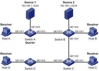
Figure 1-5 Network diagram for IGMP Snooping querier configuration
Networking and configuration requirements
l As shown in Figure 1-5, in a Layer 2–only network environment, two multicast sources Source 1 and Source 2 send multicast data to multicast groups 224.1.1.1 and 225.1.1.1 respectively, Host A and Host C are receivers of multicast group 224.1.1.1, while Host B and Host D are receivers of multicast group 225.1.1.1.
l All the receivers are running IGMPv2, and all the switches need to run IGMP Snooping version 2. Switch A, which is close to the multicast sources, is chosen as the IGMP Snooping querier.
l To prevent flooding of unknown multicast traffic within the VLAN, it is required to configure all the switches to drop unknown multicast data packets.
l Because a switch does not enlist a port that has heard an IGMP query with a source IP address of 0.0.0.0 (default) as a dynamic router port, it is required configure a non-all-zero IP address as the source IP address of IGMP queries to ensure normal creation of Layer 2 multicast forwarding entries.
Applicable product matrix
|
Product |
Software version |
Hardware version |
|
S3610 Series Ethernet Switches |
Release 5301, Release 5303 |
All versions |
|
S5510 Series Ethernet Switches |
Release 5301, Release 5303 |
All versions |
|
S5500-SI Series Ethernet Switches |
Release 1207 |
All versions (except S5500-20TP-SI) |
|
Release 1301 |
S5500-20TP-SI |
|
|
S5500-EI Series Ethernet Switches |
Release 2102 |
All versions |
|
S7500E Series Ethernet Switches |
Release 6100, Release 6300 |
All versions |
Configuration procedure
1) Configure Switch A
# Enable IGMP Snooping globally.
<SwitchA> system-view
[SwitchA] igmp-snooping
[SwitchA-igmp-snooping] quit
# Create VLAN 100 and assign GigabitEthernet 1/0/1 through GigabitEthernet 1/0/3 to the VLAN.
[SwitchA] vlan 100
[SwitchA-vlan100] port GigabitEthernet 1/0/1 to GigabitEthernet 1/0/3
# Enable IGMP Snooping and the function of dropping unknown multicast traffic in VLAN 100.
[SwitchA-vlan100] igmp-snooping enable
[SwitchA-vlan100] igmp-snooping drop-unknown
# Enable the IGMP Snooping querier function in VLAN 100
[SwitchA-vlan100] igmp-snooping querier
# Set the source IP address of IGMP general queries and group-specific queries to 192.168.1.1 in VLAN 100.
[SwitchA-vlan100] igmp-snooping general-query source-ip 192.168.1.1
[SwitchA-vlan100] igmp-snooping special-query source-ip 192.168.1.1
2) Configure Switch B
# Enable IGMP Snooping globally.
<SwitchB> system-view
[SwitchB] igmp-snooping
[SwitchB-igmp-snooping] quit
# Create VLAN 100, and assign GigabitEthernet 1/0/1 through GigabitEthernet 1/0/4 to the VLAN.
[SwitchB] vlan 100
[SwitchB-vlan100] port GigabitEthernet 1/0/1 to GigabitEthernet 1/0/4
# Enable IGMP Snooping and the function of dropping unknown multicast traffic in VLAN 100.
[SwitchB-vlan100] igmp-snooping enable
[SwitchB-vlan100] igmp-snooping drop-unknown
[SwitchB-vlan100] quit
Configurations on Switch C and Switch D are similar to the configuration on Switch B.
3) Verify the configuration
After the IGMP Snooping querier starts to work, all the switches but the querier can receive IGMP general queries. By using the display igmp-snooping statistics command, you can view the statistics information about the IGMP messages received. For example:
# View the IGMP message statistics on Switch B.
[SwitchB-vlan100] display igmp-snooping statistics
Received IGMP general queries:3.
Received IGMPv1 reports:0.
Received IGMPv2 reports:12.
Received IGMP leaves:0.
Received IGMPv2 specific queries:0.
Sent IGMPv2 specific queries:0.
Received IGMPv3 reports:0.
Received IGMPv3 reports with right and wrong records:0.
Received IGMPv3 specific queries:0.
Received IGMPv3 specific sg queries:0.
Sent IGMPv3 specific queries:0.
Sent IGMPv3 specific sg queries:0.
Received error IGMP messages:0.
Complete configuration
1) Configuration on Switch A
#
igmp-snooping
#
vlan 100
igmp-snooping enable
igmp-snooping drop-unknown
igmp-snooping querier
igmp-snooping general-query source-ip 192.168.1.1
igmp-snooping special-query source-ip 192.168.1.1
#
interface GigabitEthernet1/0/1
port access vlan 100
#
interface GigabitEthernet1/0/2
port access vlan 100
#
interface GigabitEthernet1/0/3
port access vlan 100
#
2) Configuration on Switch B
#
igmp-snooping
#
vlan 100
igmp-snooping enable
igmp-snooping drop-unknown
#
interface GigabitEthernet1/0/1
port access vlan 100
#
interface GigabitEthernet1/0/2
port access vlan 100
#
interface GigabitEthernet1/0/3
port access vlan 100
#
interface GigabitEthernet1/0/4
port access vlan 100
#
The configuration on Switch C and Switch D is similar to the configuration on Switch B.
Configuration guidelines
l It is meaningless to configure an IGMP Snooping querier in a multicast network running IGMP. Although an IGMP Snooping querier does not take part in IGMP querier elections, it may affect IGMP querier elections because it sends IGMP general queries with a low source IP address.
l Make sure that the IGMP query interval is greater than the maximum response time for IGMP general queries; otherwise, multicast group members may be wrongly removed.
Multicast VLAN Configuration Examples
In the traditional multicast programs-on-demand mode, when hosts, Host A, Host B and Host C, belonging to different VLANs require multicast programs on demand service, the Layer 3 device, Router A, needs to forward a separate copy of the multicast traffic in each user VLAN. This results in not only waste of network bandwidth but also extra burden on the Layer 3 device.
Configuring Sub-VLAN-Based IPv4 Multicast VLAN
Network diagram
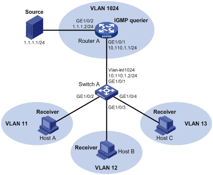
Figure 1-6 Network diagram for sub-VLAN-based IPv4 multicast VLAN configuration
Networking and configuration requirements
l As shown in Figure 1-6, Router A connects to a multicast source through GigabitEthernet 1/0/2 and to Switch A through GigabitEthernet 1/0/1.
l IGMP is required on Router A, and IGMP Snooping is required on Switch A. Router A is the IGMP querier.
l On Switch A, GigabitEthernet 1/0/1 belongs to VLAN 1024, GigabitEthernet 1/0/2 through GigabitEthernet 1/0/4 belong to VLAN 11 through VLAN 13 respectively. Host A through Host C are attached to GigabitEthernet 1/0/2 through GigabitEthernet 1/0/4 of Switch A.
l Configure the multicast VLAN feature so that Router A just sends multicast data to VLAN 1024 rather than to each VLAN when the three hosts attached to Switch A need the multicast data.
Applicable product matrix
|
Product |
Software version |
Hardware version |
|
S3610 Series Ethernet Switches |
Release 5301, Release 5303 |
All versions |
|
S5510 Series Ethernet Switches |
Release 5301, Release 5303 |
All versions |
|
S5500-SI Series Ethernet Switches |
Release 1207 |
All versions (except S5500-20TP-SI) |
|
Release 1301 |
S5500-20TP-SI |
|
|
S5500-EI Series Ethernet Switches |
Release 2102 |
All versions |
|
S7500E Series Ethernet Switches |
Release 6100, Release 6300 |
All versions |
Configuration procedure
1) Configure IP addresses
Configure an IP address and subnet mask for each interface as per Figure 1-6. The detailed configuration steps are omitted here.
2) Configure Router A
# Enable IP multicast routing, enable PIM-DM on each interface, and enable IGMP on GigabitEthernet 1/0/1.
<RouterA> system-view
[RouterA] multicast routing-enable
[RouterA] interface GigabitEthernet 1/0/1
[RouterA-GigabitEthernet1/0/1] pim dm
[RouterA-GigabitEthernet1/0/1] igmp enable
[RouterA-GigabitEthernet1/0/1] quit
[RouterA] interface GigabitEthernet 1/0/2
[RouterA-GigabitEthernet1/0/2] pim dm
[RouterA-GigabitEthernet1/0/2] quit
3) Configure Switch A
# Enable IGMP Snooping globally.
<SwitchA> system-view
[SwitchA] igmp-snooping
[SwitchA-igmp-snooping] quit
# Create VLAN 11 and assign GigabitEthernet 1/0/2 to this VLAN.
[SwitchA] vlan 11
[SwitchA-vlan11] port GigabitEthernet 1/0/2
[SwitchA-vlan11] quit
The configuration for VLAN 12 and VLAN 13 is similar to the configuration for VLAN 11.
# Create VLAN 1024, assign GigabitEthernet 1/0/1 to this VLAN, and enable IGMP Snooping in the VLAN.
[SwitchA] vlan 1024
[SwitchA-vlan1024] port GigabitEthernet 1/0/1
[SwitchA-vlan1024] igmp-snooping enable
[SwitchA-vlan1024] quit
# Configure VLAN 1024 as a multicast VLAN and configure VLAN 11 through VLAN 13 as its sub-VLANs.
[SwitchA] multicast-vlan 1024 enable
[SwitchA] multicast-vlan 1024 subvlan 11 to 13
4) Verify the configuration
# View information about the multicast VLAN and its sub-VLANs on Switch A.
[SwitchA] display multicast-vlan
multicast vlan 1024's subvlan list:
vlan 11-13
Complete configuration
1) Configuration on Switch A
#
igmp-snooping
#
vlan 11 to 13
#
interface GigabitEthernet1/0/2
port access vlan 11
#
interface GigabitEthernet1/0/3
port access vlan 12
#
interface GigabitEthernet1/0/4
port access vlan 13
#
interface GigabitEthernet1/0/1
port access vlan 1024
#
multicast-vlan 1024 enable
multicast-vlan 1024 subvlan 11 to 13
#
Configuration guildlines
l You cannot configure any multicast VLAN or a sub-VLAN of a multicast VLAN on a device with IP multicast routing enabled.
l After a VLAN is configured as a multicast VLAN, IGMP Snooping must be enabled in the VLAN before the multicast VLAN feature can be implemented; while it is not necessary to enable IGMP Snooping in the sub-VLANs of the multicast VLAN.
Configuring Port-Based IPv4 Multicast VLAN
Network diagram
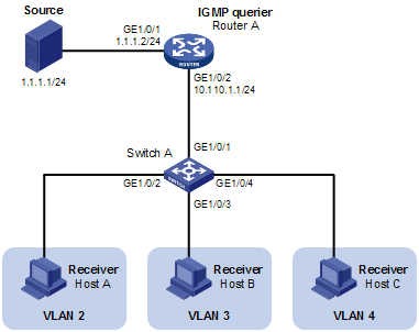
Figure 1-7 Network diagram for port-based IPv4 multicast VLAN configuration
Network requirements
l As shown in Figure 1-7, Router A connects to a multicast source (Source) through GigabitEthernet 1/0/1, and to Switch A through GigabitEthernet 1/0/2.
l IGMPv2 is required on Router A. IGMPv2 Snooping is required on Switch A. Router A acts as the IGMP querier.
l Switch A’s GigabitEthernet 1/0/1 belongs to VLAN 10, GigabitEthernet 1/0/2 through GigabitEthernet 1/0/4 belong to VLAN 2 through VLAN 4 respectively, and Host A through Host C are attached to GigabitEthernet 1/0/2 through GigabitEthernet1/0/4 of Switch A respectively.
l The multicast source sends multicast data to multicast group 224.1.1.1. Host A, Host B, and Host C are receivers of the multicast group.
l Configure the port-based multicast VLAN feature so that Router A just sends multicast data to Switch A through the multicast VLAN and Switch A forwards the multicast data to the receivers that belong to different user VLANs.
Applicable product matrix
|
Product |
Software version |
Hardware version |
|
S7500E Series Ethernet Switches |
Release 6300 |
All versions |
Configuration procedure
1) Configure IP addresses
Configure the IP address and subnet mask for each interface as per Figure 1-7. The detailed configuration steps are omitted here.
2) Configure Router A
# Enable IP multicast routing, enable PIM-DM on each interface, and enable IGMP on the host-side interface GigabitEthernet 1/0/2.
<RouterA> system-view
[RouterA] multicast routing-enable
[RouterA] interface gigabitethernet 1/0/1
[RouterA-GigabitEthernet1/0/1] pim dm
[RouterA-GigabitEthernet1/0/1] quit
[RouterA] interface gigabitethernet 1/0/2
[RouterA-GigabitEthernet1/0/2] pim dm
[RouterA-GigabitEthernet1/0/2] igmp enable
3) Configure Switch A
# Enable IGMP Snooping globally.
<SwitchA> system-view
[SwitchA] igmp-snooping
[SwitchA-igmp-snooping] quit
# Create VLAN 10, assign GigabitEthernet 1/0/1 to VLAN 10, and enable IGMP Snooping in this VLAN.
[SwitchA] vlan 10
[SwitchA-vlan10] port gigabitethernet 1/0/1
[SwitchA-vlan10] igmp-snooping enable
[SwitchA-vlan10] quit
# Create VLAN 2 and enable IGMP Snooping in the VLAN.
[SwitchA] vlan 2
[SwitchA-vlan2] igmp-snooping enable
[SwitchA-vlan2] quit
The configuration for VLAN 3 and VLAN 4 is similar. The detailed configuration steps are omitted.
# Configure GigabitEthernet 1/0/2 as a hybrid port. Configure VLAN 2 as the default VLAN. Configure GigabitEthernet 1/0/2 to permit packets of VLAN 2 and VLAN 10 to pass and untag the packets when forwarding them.
[SwitchA] interface gigabitethernet 1/0/2
[SwitchA-GigabitEthernet1/0/2] port link-type hybrid
[SwitchA-GigabitEthernet1/0/2] port hybrid pvid vlan 2
[SwitchA-GigabitEthernet1/0/2] port hybrid vlan 2 untagged
[SwitchA-GigabitEthernet1/0/2] port hybrid vlan 10 untagged
[SwitchA-GigabitEthernet1/0/2] quit
The configuration for GigabitEthernet 1/0/3 and GigabitEthernet 1/0/4 is similar. The detailed configuration steps are omitted.
# Configure VLAN 10 as a multicast VLAN.
[SwitchA] multicast-vlan 10
# Assign GigabitEthernet 1/0/2 and GigabitEthernet 1/0/3 to VLAN 10.
[SwitchA-mvlan-10] port gigabitethernet 1/0/2 to gigabitethernet 1/0/3
[SwitchA-mvlan-10] quit
# Assign GigabitEthernet 1/0/4 to VLAN 10.
[SwitchA] interface gigabitethernet 1/0/4
[SwitchA-GigabitEthernet1/0/4] port multicast-vlan 10
[SwitchA-GigabitEthernet1/0/4] quit
4) Verify the configuration
# View the multicast VLAN information on Switch A.
[SwitchA] display multicast-vlan
Total 1 multicast-vlan(s)
Multicast vlan 10
subvlan list:
no subvlan
port list:
GE1/0/2 GE1/0/3 GE1/0/4
# View the IGMP Snooping multicast group information on Switch A.
[SwitchA] display igmp-snooping group
Total 1 IP Group(s).
Total 1 IP Source(s).
Total 1 MAC Group(s).
Port flags: D-Dynamic port, S-Static port, C-Copy port
Subvlan flags: R-Real VLAN, C-Copy VLAN
Vlan(id):10.
Total 1 IP Group(s).
Total 1 IP Source(s).
Total 1 MAC Group(s).
Router port(s):total 1 port.
GE1/0/1 (D)
IP group(s):the following ip group(s) match to one mac group.
IP group address:224.1.1.1
(0.0.0.0, 224.1.1.1):
Host port(s):total 3 port.
GE1/0/2 (D)
GE1/0/3 (D)
GE1/0/4 (D)
MAC group(s):
MAC group address:0100-5e01-0101
Host port(s):total 3 port.
GE1/0/2
GE1/0/3
GE1/0/4
As shown above, IGMP Snooping is maintaining the router ports and member ports in VLAN 10.
Complete configuration
1) Configuration on SwitchA
#
igmp-snooping
#
vlan 2
igmp-snooping enable
#
vlan 3
igmp-snooping enable
#
vlan 4
igmp-snooping enable
#
vlan 10
igmp-snooping enable
#
interface GigabitEthernet2/0/1
port access vlan 10
#
interface GigabitEthernet2/0/2
port link-type hybrid
port hybrid vlan 1 to 2 10 untagged
port hybrid pvid vlan 2
#
interface GigabitEthernet2/0/3
port link-type hybrid
port hybrid vlan 1 3 10 untagged
port hybrid pvid vlan 3
#
interface GigabitEthernet2/0/4
port link-type hybrid
port hybrid vlan 1 4 10 untagged
port hybrid pvid vlan 4
#
multicast-vlan 10
port GigabitEthernet2/0/2 to GigabitEthernet2/0/4
Configuration guidelines
l A port can belong to only one multicast VLAN.
l You cannot configure multicast VLAN on a device with multicast routing enabled.
PIM Configuration Examples
Configuring PIM-DM
Network diagram
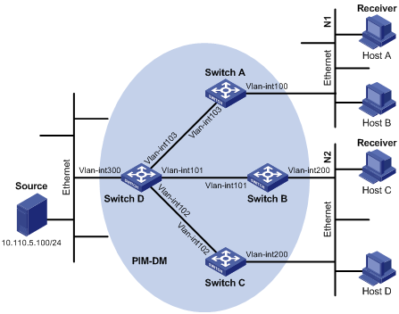
Figure 1-8 Network diagram for PIM-DM configuration
|
Device |
Interface |
IP address |
Device |
Interface |
IP address |
|
Switch A |
Vlan-int 100 |
10.110.1.1/24 |
Switch D |
Vlan-int 300 |
10.110.5.1/24 |
|
|
Vlan-int 103 |
192.168.1.1/24 |
|
Vlan-int 103 |
192.168.1.2/24 |
|
Switch B |
Vlan-int 200 |
10.110.2.1/24 |
|
Vlan-int 101 |
192.168.2.2/24 |
|
|
Vlan-int 101 |
192.168.2.1/24 |
|
Vlan-int 102 |
192.168.3.2/24 |
|
Switch C |
Vlan-int 200 |
10.110.2.2/24 |
|
|
|
|
|
Vlan-int 102 |
192.168.3.1/24 |
|
|
|
Networking and configuration requirements
l Receivers receive VOD information through multicast. The receiver groups of different organizations form stub networks, and one or more receiver hosts exist in each stub network. The entire PIM domain operates in the dense mode.
l Host A and Host C are multicast receivers in two stub networks. Switch D connects to the network that comprises the multicast source (Source) through VLAN-interface 300. Switch A connects to stub network N1 through VLAN-interface 100, and to Switch D through VLAN-interface 103. Switch B and Switch C connect to stub network N2 through their respective VLAN-interface 200, and to Switch D through VLAN-interface 101 and VLAN-interface 102 respectively.
l IGMPv2 is to run between Switch A and N1, and between Switch B/Switch C and N2.
Applicable product matrix
|
Product |
Software version |
Hardware version |
|
S3610 Series Ethernet Switches |
Release 5301, Release 5303 |
All versions |
|
S5510 Series Ethernet Switches |
Release 5301, Release 5303 |
All versions |
|
S5500-EI Series Ethernet Switches |
Release 2102 |
All versions |
|
S7500E Series Ethernet Switches |
Release 6100, Release 6303 |
All versions |
Configuration procedure
1) Configure IP addresses and unicast routing
Configure an IP address and subnet mask for each interface as per Figure 1-8. Detailed configuration steps are omitted here.
Configure the OSPF protocol for interoperation among switches in the PIM-DM domain. Ensure dynamic update of routing information among the switches through a unicast routing protocol. Detailed configuration steps are omitted here.
2) Enable IP multicast routing, and enable PIM-DM and IGMP on each interface
# Enable IP multicast routing on Switch A, enable PIM-DM on each interface, and enable IGMPv2 on VLAN-interface 100, which connects Switch A to the stub network.
<SwitchA> system-view
[SwitchA] multicast routing-enable
[SwitchA] interface vlan-interface 100
[SwitchA-Vlan-interface100] igmp enable
[SwitchA-Vlan-interface100] pim dm
[SwitchA-Vlan-interface100] quit
[SwitchA] interface vlan-interface 103
[SwitchA-Vlan-interface103] pim dm
[SwitchA-Vlan-interface103] quit
The configuration on Switch B and Switch C is similar to that on Switch A.
# Enable IP multicast routing on Switch D, and enable PIM-DM on each interface.
<SwitchD> system-view
[SwitchD] multicast routing-enable
[SwitchD] interface vlan-interface 300
[SwitchD-Vlan-interface300] pim dm
[SwitchD-Vlan-interface300] quit
[SwitchD] interface vlan-interface 103
[SwitchD-Vlan-interface103] pim dm
[SwitchD-Vlan-interface103] quit
[SwitchD] interface vlan-interface 101
[SwitchD-Vlan-interface101] pim dm
[SwitchD-Vlan-interface101] quit
[SwitchD] interface vlan-interface 102
[SwitchD-Vlan-interface102] pim dm
[SwitchD-Vlan-interface102] quit
3) Verify the configuration
Use the display pim interface command to view the PIM configuration and running status on each interface. For example:
# View the PIM configuration information on Switch D.
[SwitchD] display pim interface
Interface NbrCnt HelloInt DR-Pri DR-Address
Vlan300 0 30 1 10.110.5.1 (local)
Vlan103 1 30 1 192.168.1.2 (local)
Vlan101 1 30 1 192.168.2.2 (local)
Vlan102 1 30 1 192.168.3.2 (local)
Use the display pim neighbor command to view the PIM neighboring relationships among the switches. For example:
# View the PIM neighboring relationships on Switch D.
[SwitchD] display pim neighbor
Total Number of Neighbors = 3
Neighbor Interface Uptime Expires Dr-Priority
192.168.1.1 Vlan103 00:02:22 00:01:27 1
192.168.2.1 Vlan101 00:00:22 00:01:29 3
192.168.3.1 Vlan102 00:00:23 00:01:31 5
Assume that Host A needs to receive the information addressed to a multicast group G (225.1.1.1/24). After multicast source S (10.110.5.100/24) sends multicast packets to 225.1.1.1/24, an SPT is established through traffic flooding. Switches on the SPT path (Switch A and Switch D) have their (S, G) entries. Host A registers with Switch A, and a (*, G) entry is generated on Switch A.
You can use the display pim routing-table command to view the PIM routing table information on each switch. For example:
# View the PIM routing table information on Switch A.
[SwitchA] display pim routing-table
Total 1 (*, G) entry; 1 (S, G) entry
(*, 225.1.1.1)
Protocol: pim-dm, Flag: WC
UpTime: 00:04:25
Upstream interface: NULL
Upstream neighbor: NULL
RPF prime neighbor: NULL
Downstream interface(s) information:
Total number of downstreams: 1
1: Vlan-interface100
Protocol: igmp, UpTime: 00:04:25, Expires: never
(10.110.5.100, 225.1.1.1)
Protocol: pim-dm, Flag: ACT
UpTime: 00:06:14
Upstream interface: Vlan-interface103,
Upstream neighbor: 192.168.1.2
RPF prime neighbor: 192.168.1.2
Downstream interface(s) information:
Total number of downstreams: 1
1: Vlan-interface100
Protocol: pim-dm, UpTime: 00:04:25, Expires: never
The information on Switch B and Switch C is similar to that on Switch A.
# View the PIM routing table information on Switch D.
[SwitchD] display pim routing-table
Total 0 (*, G) entry; 1 (S, G) entry
(10.110.5.100, 225.1.1.1)
Protocol: pim-dm, Flag: LOC ACT
UpTime: 00:03:27
Upstream interface: Vlan-interface300
Upstream neighbor: NULL
RPF prime neighbor: NULL
Downstream interface(s) information:
Total number of downstreams: 3
1: Vlan-interface103
Protocol: pim-dm, UpTime: 00:03:27, Expires: never
2: Vlan-interface101
Protocol: pim-dm, UpTime: 00:03:27, Expires: never
3: Vlan-interface102
Protocol: pim-dm, UpTime: 00:03:27, Expires: never
Complete configuration
1) Configuration on Switch A
#
multicast routing-enable
#
interface Vlan-interface100
ip address 10.110.1.1 255.255.255.0.
igmp enable
pim dm
#
interface Vlan-interface103
ip address 192.168.1.1 255.255.255.0
pim dm
#
2) Configuration on Switch B
#
multicast routing-enable
#
interface Vlan-interface101
ip address 192.168.2.1 255.255.255.0.
pim dm
#
interface Vlan-interface200
ip address 10.110.2.1 255.255.255.0
igmp enable
pim dm
#
3) Configuration on Switch C
#
multicast routing-enable
#
interface Vlan-interface102
ip address 192.168.3.1 255.255.255.0.
pim dm
#
interface Vlan-interface200
ip address 10.110.2.2 255.255.255.0
igmp enable
pim dm
#
4) Configuration on Switch D
#
multicast routing-enable
#
interface Vlan-interface101
ip address 192.168.2.2 255.255.255.0.
pim dm
#
interface Vlan-interface102
ip address 192.168.3.2 255.255.255.0
pim dm
#
interface Vlan-interface103
ip address 192.168.1.2 255.255.255.0
pim dm
#
interface Vlan-interface300
ip address 10.110.5.1 255.255.255.0
pim dm
#
Configuration guildlines
When deploying a PIM-DM domain, you are recommended to enable PIM-DM on interfaces of all the non-border switches.
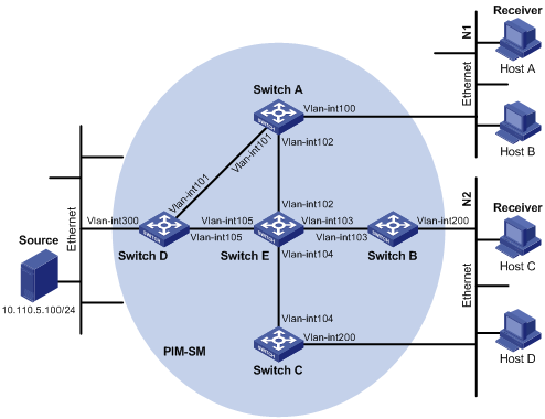
Configuring PIM-SM Non-Scoped Zone
Network diagram
Figure 1-9 Network diagram for PIM-SM configuration
|
Device |
Interface |
IP address |
Device |
Interface |
IP address |
|
Switch A |
Vlan-int 100 |
10.110.1.1/24 |
Switch D |
Vlan-int 300 |
10.110.5.1/24 |
|
|
Vlan-int 101 |
192.168.1.1/24 |
|
Vlan-int 101 |
192.168.1.2/24 |
|
|
Vlan-int 102 |
192.168.9.1/24 |
|
Vlan-int 105 |
192.168.4.2/24 |
|
Switch B |
Vlan-int 200 |
10.110.2.1/24 |
Switch E |
Vlan-int 104 |
192.168.3.2/24 |
|
|
Vlan-int 103 |
192.168.2.1/24 |
|
Vlan-int 103 |
192.168.2.2/24 |
|
Switch C |
Vlan-int 200 |
10.110.2.2/24 |
|
Vlan-int 102 |
192.168.9.2/24 |
|
|
Vlan-int 104 |
192.168.3.1/24 |
|
Vlan-int 105 |
192.168.4.1/24 |
Networking and configuration requirements
l Receivers receive VOD information through multicast. The receiver groups of different organizations form stub networks, and one or more receiver hosts exist in each stub network. The entire PIM domain is a non-scoped zone running PIM-SM.
l Host A and Host C are multicast receivers in two stub networks. Switch D connects to the network that comprises the multicast source (Source) through VLAN-interface 300. Switch A connects to stub network N1 through VLAN-interface 100, and to Switch D and Switch E through VLAN-interface 101 and VLAN-interface 102 respectively.
l Switch B and Switch C connect to stub network N2 through their respective VLAN-interface 200, and to Switch E through VLAN-interface 103 and VLAN-interface 104 respectively.
l Vlan-interface 105 on Switch D and Vlan-interface 102 on Switch E act as C-BSRs and C-RPs; the C-BSR on Switch E has a higher priority; the multicast group range served by the C-RP is 225.1.1.0/24; modify the hash mask length to map a certain number of consecutive group addresses within the range to the two C-RPs.
l IGMPv2 is to run between Switch A and N1, and between Switch B/Switch C and N2.
Applicable product matrix
|
Product |
Software version |
Hardware version |
|
S3610 Series Ethernet Switches |
Release 5301, Release 5303 |
All versions |
|
S5510 Series Ethernet Switches |
Release 5301, Release 5303 |
All versions |
|
S5500-EI Series Ethernet Switches |
Release 2102 |
All versions |
|
S7500E Series Ethernet Switches |
Release 6100, Release 6300 |
All versions |
Configuration procedure
1) Configure IP addresses and unicast routing
Configure the IP address and subnet mask for each interface as per Figure 1-9. Detailed configuration steps are omitted here.
Configure the OSPF protocol for interoperation among the switches in the PIM-SM domain. Ensure the network-layer interoperation in the PIM-SM domain and enable dynamic update of routing information among the switches through unicast routing. Detailed configuration steps are omitted here.
2) Enable IP multicast routing, and enable PIM-SM and IGMP
# Enable IP multicast routing on Switch A, enable PIM-SM on each interface, and enable IGMP on VLAN-interface 100, which connects Switch A to the stub network.
<SwitchA> system-view
[SwitchA] multicast routing-enable
[SwitchA] interface vlan-interface 100
[SwitchA-Vlan-interface100] igmp enable
[SwitchA-Vlan-interface100] pim sm
[SwitchA-Vlan-interface100] quit
[SwitchA] interface vlan-interface 101
[SwitchA-Vlan-interface101] pim sm
[SwitchA-Vlan-interface101] quit
[SwitchA] interface vlan-interface 102
[SwitchA-Vlan-interface102] pim sm
[SwitchA-Vlan-interface102] quit
The configuration on Switch B and Switch C is similar to that on Switch A. The configuration on Switch D and Switch E is also similar to that on Switch A except that it is not necessary to enable IGMP on the corresponding interfaces of these two switches.
3) Configure a C-BSR and a C-RP
# On Switch D, configure the service scope of RP advertisements, specify a C-BSR and a C-RP, and set the hash mask length to 32 and the priority of the C-BSR to 10.
<SwitchD> system-view
[SwitchD] acl number 2005
[SwitchD-acl-basic-2005] rule permit source 225.1.1.0 0.0.0.255
[SwitchD-acl-basic-2005] quit
[SwitchD] pim
[SwitchD-pim] c-bsr vlan-interface 105 32 10
[SwitchD-pim] c-rp vlan-interface 105 group-policy 2005
[SwitchD-pim] quit
# On Switch E, configure the service scope of RP advertisements, specify a C-BSR and a C-RP; and set the hash mask length to 32 and the priority of the C-BSR to 20.
<SwitchE> system-view
[SwitchE] acl number 2005
[SwitchE-acl-basic-2005] rule permit source 225.1.1.0 0.0.0.255
[SwitchE-acl-basic-2005] quit
[SwitchE] pim
[SwitchE-pim] c-bsr vlan-interface 102 32 20
[SwitchE-pim] c-rp vlan-interface 102 group-policy 2005
[SwitchE-pim] quit
4) Verify the configuration
Use the display pim interface command to view the PIM configuration and running status on a switch. For example:
# View the PIM configuration information on Switch A.
[SwitchA] display pim interface
Interface NbrCnt HelloInt DR-Pri DR-Address
Vlan100 0 30 1 10.110.1.1 (local)
Vlan101 1 30 1 192.168.1.2
Vlan102 1 30 1 192.168.9.2
Use the display pim bsr-info command to view the BSR election information and the locally configured C-RP information in effect on a switch. For example:
# View the BSR information and the locally configured C-RP information in effect on Switch A.
[SwitchA] display pim bsr-info
Elected BSR Address: 192.168.9.2
Priority: 20
Hash mask length: 32
State: Accept Preferred
Scope: Not scoped
Uptime: 01:40:40
Expires: 00:01:42
# View the BSR information and the locally configured C-RP information in effect on Switch D.
[SwitchD] display pim bsr-info
Elected BSR Address: 192.168.9.2
Priority: 20
Hash mask length: 32
State: Accept Preferred
Scope: Not scoped
Uptime: 00:05:26
Expires: 00:01:45
Candidate BSR Address: 192.168.4.2
Priority: 10
Hash mask length: 32
State: Candidate
Scope: Not scoped
Candidate RP: 192.168.4.2(Vlan-interface105)
Priority: 0
HoldTime: 150
Advertisement Interval: 60
Next advertisement scheduled at: 00:00:34
# View the BSR information and the locally configured C-RP information in effect on Switch E.
[SwitchE] display pim bsr-info
Elected BSR Address: 192.168.9.2
Priority: 20
Hash mask length: 32
State: Elected
Scope: Not scoped
Uptime: 00:00:18
Next BSR message scheduled at: 00:01:52
Candidate BSR Address: 192.168.9.2
Priority: 20
Hash mask length: 32
State: Elected
Scope: Not scoped
Candidate RP: 192.168.9.2(Vlan-interface102)
Priority: 0
HoldTime: 150
Advertisement Interval: 60
Next advertisement scheduled at: 00:00:48
To view the RP information learnt on a switch, use the display pim rp-info command. For example:
# View the RP information on Switch A.
[SwitchA] display pim rp-info
PIM-SM BSR RP information:
Group/MaskLen: 225.1.1.0/24
RP: 192.168.4.2
Priority: 0
HoldTime: 150
Uptime: 00:51:45
Expires: 00:02:22
RP: 192.168.9.2
Priority: 0
HoldTime: 150
Uptime: 00:51:45
Expires: 00:02:22
Assume that Host A needs to receive information addressed to the multicast group G (225.1.1.0). The RP corresponding to the multicast group is Switch E as a result of hash calculation, so an RPT will be built between Switch A and Switch E.
When the multicast source S (10.110.5.100/24) registers with the RP, an SPT will be built between Switch D and Switch E. Upon receiving multicast data, Switch A immediately switches from the RPT to the SPT.
Switches on the RPT path (Switch A and Switch E) have a (*, G) entry, while switches on the SPT path (Switch A and Switch D) have an (S, G) entry.
You can use the display pim routing-table command to view the PIM routing table information on the switches. For example:
# View the PIM routing table information on Switch A.
[SwitchA] display pim routing-table
Total 1 (*, G) entry; 1 (S, G) entry
(*, 225.1.1.0)
RP: 192.168.9.2
Protocol: pim-sm, Flag: WC
UpTime: 00:13:46
Upstream interface: Vlan-interface102,
Upstream neighbor: 192.168.1.2
RPF prime neighbor: 192.168.1.2
Downstream interface(s) information:
Total number of downstreams: 1
1: Vlan-interface100
Protocol: igmp, UpTime: 00:13:46, Expires:00:03:06
(10.110.5.100, 225.1.1.0)
RP: 192.168.9.2
Protocol: pim-sm, Flag: SPT ACT
UpTime: 00:00:42
Upstream interface: Vlan-interface101,
Upstream neighbor: 192.168.9.2
RPF prime neighbor: 192.168.9.2
Downstream interface(s) information:
Total number of downstreams: 1
1: Vlan-interface100
Protocol: pim-sm, UpTime: 00:00:42, Expires:00:03:06
The information on Switch B and Switch C is similar to that on Switch A.
# View the PIM routing table information on Switch D.
[SwitchD] display pim routing-table
Total 0 (*, G) entry; 1 (S, G) entry
(10.110.5.100, 225.1.1.0)
RP: 192.168.9.2
Protocol: pim-sm, Flag: SPT ACT
UpTime: 00:00:42
Upstream interface: Vlan-interface300
Upstream neighbor: NULL
RPF prime neighbor: NULL
Downstream interface(s) information:
Total number of downstreams: 1
1: Vlan-interface105
Protocol: pim-sm, UpTime: 00:00:42, Expires:00:02:06
# View the PIM routing table information on Switch E.
[SwitchE] display pim routing-table
Total 1 (*, G) entry; 0 (S, G) entry
(*, 225.1.1.0)
RP: 192.168.9.2 (local)
Protocol: pim-sm, Flag: WC
UpTime: 00:13:16
Upstream interface: Register
Upstream neighbor: 192.168.4.2
RPF prime neighbor: 192.168.4.2
Downstream interface(s) information:
Total number of downstreams: 1
1: Vlan-interface102
Protocol: pim-sm, UpTime: 00:13:16, Expires: 00:03:22
Complete configuration
1) Configuration on Switch A
#
multicast routing-enable
#
interface Vlan-interface100
ip address 10.110.1.1 255.255.255.0
igmp enable
pim sm
#
interface Vlan-interface101
ip address 192.168.1.1 255.255.255.0
pim sm
#
interface Vlan-interface102
ip address 192.168.9.1 255.255.255.0
pim sm
#
2) Configuration on Switch B
#
multicast routing-enable
#
interface Vlan-interface103
ip address 192.168.2.1 255.255.255.0
pim sm
#
interface Vlan-interface200
ip address 10.110.2.1 255.255.255.0
igmp enable
pim sm
#
3) Configuration on Switch C
#
multicast routing-enable
#
interface Vlan-interface104
ip address 192.168.3.1 255.255.255.0
pim sm
#
interface Vlan-interface200
ip address 10.110.2.2 255.255.255.0
igmp enable
pim sm
#
4) Configuration on Switch D
#
acl number 2005
rule 0 permit source 225.1.1.0 0.0.0.255
#
multicast routing-enable
#
interface Vlan-interface101
ip address 192.168.1.2 255.255.255.0
pim sm
#
interface Vlan-interface105
ip address 192.168.4.2 255.255.255.0
pim sm
#
interface Vlan-interface300
ip address 10.110.5.1 255.255.255.0
pim sm
#
pim
c-bsr Vlan-interface105 32 10
c-rp Vlan-interface105 group-policy 2005
#
5) Configuration on Switch E
#
acl number 2005
rule 0 permit source 225.1.1.0 0.0.0.255
#
multicast routing-enable
#
interface Vlan-interface102
ip address 192.168.9.2 255.255.255.0
pim sm
#
interface Vlan-interface103
ip address 192.168.2.2 255.255.255.0
pim sm
#
interface Vlan-interface104
ip address 192.168.3.2 255.255.255.0
pim sm
#
interface Vlan-interface105
ip address 192.168.4.1 255.255.255.0
pim sm
#
pim
c-bsr Vlan-interface102 32 20
c-rp Vlan-interface102 group-policy 2005
#
Configuration guildlines
l Only one C-BSR can be configured on a Layer 3 switch; a newly configured C-BSR on another interface on the same switch will replace the existing configuration.
l C-BSRs and C-RPs should be configured on Layer 3 switches in the backbone network.
l If a service scope is not specified in the RP configuration, the RP will serve all multicast groups; if a service scope is specified, the RP will serve the specified multicast groups.
l An ACL rule can be configured to filter multicast addresses, and thus to control the multicast group range to be served by the static RP.
l To enable a static RP to work normally, all routers in the same PIM domain must have the same static RP configuration.
l If the address of an interface in the up state is specified as the static RP address, the current device serves as a static RP.
l With the RP elected through the BSR mechanism in effect, the static RP does not function.
l It is unnecessary to enable PIM on the interface acting as a static RP.
l Configuring a legal range of BSR addresses can prevent maliciously configured hosts from masquerading as a BSR. All the Layer 3 switches on the network will discard bootstrap messages from out of the legal address range, thus protecting the security of BSR in a network.
l To guard against C-RP spoofing, you need to configure a legal C-RP address range and the range of multicast groups to be served by the C-RP.
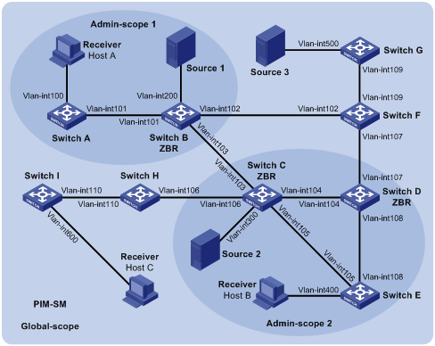
Configuring PIM-SM Administratively Scoped Zone
Network diagram
Figure 1-10 Network diagram for PIM-SM admin-scope zone configuration
|
Device |
Interface |
IP address |
Device |
Interface |
IP address |
|
Switch A |
Vlan-int 100 |
192.168.1.1/24 |
Switch D |
Vlan-int 104 |
10.110.4.2/24 |
|
|
Vlan-int 101 |
10.110.1.1/24 |
|
Vlan-int 108 |
10.110.7.1/24 |
|
Switch B |
Vlan-int200 |
192.168.2.1/24 |
|
Vlan-int 107 |
10.110.8.1/24 |
|
|
Vlan-int 101 |
10.110.1.2/24 |
Switch E |
Vlan-int 400 |
192.168.4.1/24 |
|
|
Vlan-int 103 |
10.110.2.1/24 |
|
Vlan-int 105 |
10.110.5.2/24 |
|
|
Vlan-int 102 |
10.110.3.1/24 |
|
Vlan-int 108 |
10.110.7.2/24 |
|
Switch C |
Vlan-int 300 |
192.168.3.1/24 |
Switch F |
Vlan-int 109 |
10.110.9.1/24 |
|
|
Vlan-int 104 |
10.110.4.1/24 |
|
Vlan-int 107 |
10.110.8.2/24 |
|
|
Vlan-int 105 |
10.110.5.1/24 |
|
Vlan-int 102 |
10.110.3.2/24 |
|
|
Vlan-int 103 |
10.110.2.2/24 |
Switch G |
Vlan-int 500 |
192.168.5.1/24 |
|
|
Vlan-int 106 |
10.110.6.1/24 |
|
Vlan-int 109 |
10.110.9.2/24 |
|
Switch H |
Vlan-int 110 |
10.110.10.1/24 |
Source 1 |
— |
192.168.2.10/24 |
|
|
Vlan-int 106 |
10.110.6.2/24 |
Source 2 |
— |
192.168.3.10/24 |
|
Switch I |
Vlan-int 600 |
192.168.6.1/24 |
Source 3 |
— |
192.168.5.10/24 |
|
|
Vlan-int 110 |
10.110.10.2/24 |
|
|
|
Networking and configuration requirements
l Receivers receive VOD information through multicast. The entire PIM-SM domain is divided into admin-scope zone 1, admin-scope zone 2, and the global zone. Switch B, Switch C, and Switch D are ZBRs of these three zones respectively.
l Source 1 and Source 2 send different multicast information to multicast group 239.1.1.1. Host A receives the multicast information from only Source 1, while Host B receives the multicast information from only Source 2. Source 3 sends multicast information to multicast group 224.1.1.1. Host C is a multicast receiver for this multicast group.
l VLAN-interface 101 of Switch B acts as a C-BSR and a C-RP of admin-scope zone 1, which serves the multicast group range 239.0.0.0/8. VLAN-interface 104 of Switch D acts as a C-BSR and a C-RP of admin-scope zone 2, which also serves the multicast group range 239.0.0.0/8. Both VLAN-interface 109 of Switch F and VLAN-interface 110 of Switch H act as C-BSRs and C-RPs of the global scope zone, which serve all the multicast groups other than those in the 239.0.0.0/8 range. Switch F has a higher priority.
l IGMPv2 is required between Switch A, Switch E, Switch I and their respective receivers.
Applicable product matrix
|
Product |
Software version |
Hardware version |
|
S3610 Series Ethernet Switches |
Release 5301, Release 5303 |
All versions |
|
S5510 Series Ethernet Switches |
Release 5301, Release 5303 |
All versions |
|
S5500-EI Series Ethernet Switches |
Release 2102 |
All versions |
|
S7500E Series Ethernet Switches |
Release 6100, Release 6300 |
All versions |
Configuration procedure
1) Configure IP addresses and unicast routing
Configure an IP address and subnet mask for each interface as per Figure 1-10. The detailed configuration steps are omitted here.
Configure OSPF for interoperation among the switches in the PIM-SM domain. Ensure the network-layer interoperation among the switches in the PIM-SM domain and enable dynamic update of routing information among the switches through unicast routing. Detailed configuration steps are omitted here.
2) Enable IP multicast routing and administrative scoping, and enable PIM-SM and IGMP
# Enable IP multicast routing and administrative scoping on Switch A, enable PIM-SM on each interface, and enable IGMP on the host-side interface VLAN-interface 100.
<SwitchA> system-view
[SwitchA] multicast routing-enable
[SwitchA] pim
[SwitchA-pim] c-bsr admin-scope
[SwitchA-pim] quit
[SwitchA] interface vlan-interface 100
[SwitchA-Vlan-interface100] igmp enable
[SwitchA-Vlan-interface100] pim sm
[SwitchA-Vlan-interface100] quit
[SwitchA] interface vlan-interface 101
[SwitchA-Vlan-interface101] pim sm
[SwitchA-Vlan-interface101] quit
The configuration on Switch E and Switch I is similar to the configuration on Switch A.
# On Switch B, enable IP multicast routing and administrative scoping, and enable PIM-SM on each interface.
<SwitchB> system-view
[SwitchB] multicast routing-enable
[SwitchB] pim
[SwitchB-pim] c-bsr admin-scope
[SwitchB-pim] quit
[SwitchB] interface vlan-interface 200
[SwitchB-Vlan-interface200] pim sm
[SwitchB-Vlan-interface200] quit
[SwitchB] interface vlan-interface 101
[SwitchB-Vlan-interface101] pim sm
[SwitchB-Vlan-interface101] quit
[SwitchB] interface vlan-interface 102
[SwitchB-Vlan-interface102] pim sm
[SwitchB-Vlan-interface102] quit
[SwitchB] interface vlan-interface 103
[SwitchB-Vlan-interface103] pim sm
[SwitchB-Vlan-interface103] quit
The configuration on Switch C, Switch D, Switch F, Switch G, and Switch H is similar to the configuration on Switch B. The specific configuration steps are omitted here.
3) Configure an admin-scope zone boundary
# On Switch B, configure VLAN-interface 102 and VLAN-interface 103 to be the boundary of admin-scope zone 1.
[SwitchB] interface vlan-interface 102
[SwitchB-Vlan-interface102] multicast boundary 239.0.0.0 8
[SwitchB-Vlan-interface102] quit
[SwitchB] interface vlan-interface 103
[SwitchB-Vlan-interface103] multicast boundary 239.0.0.0 8
[SwitchB-Vlan-interface103] quit
# On Switch C, configure VLAN-interface 103 and VLAN-interface 106 to be the boundary of admin-scope zone 2.
<SwitchC> system-view
[SwitchC] interface vlan-interface 103
[SwitchC-Vlan-interface103] multicast boundary 239.0.0.0 8
[SwitchC-Vlan-interface103] quit
[SwitchC] interface vlan-interface 106
[SwitchC-Vlan-interface106] multicast boundary 239.0.0.0 8
[SwitchC-Vlan-interface106] quit
# On Switch D, configure VLAN-interface 107 to be the boundary of admin-scope zone 2.
<SwitchD> system-view
[SwitchD] interface vlan-interface 107
[SwitchD-Vlan-interface107] multicast boundary 239.0.0.0 8
[SwitchD-Vlan-interface107] quit
4) Configure C-BSRs and C-RPs
# On Switch B, configure the service scope of RP advertisements and configure VLAN-interface 101 as a C-BSR and C-RP of admin-scope zone 1.
[SwitchB] acl number 2001
[SwitchB-acl-basic-2001] rule permit source 239.0.0.0 0.255.255.255
[SwitchB-acl-basic-2001] quit
[SwitchB] pim
[SwitchB-pim] c-bsr group 239.0.0.0 8
[SwitchB-pim] c-bsr vlan-interface 101
[SwitchB-pim] c-rp vlan-interface 101 group-policy 2001
[SwitchB-pim] quit
# On Switch D, configure the service scope of RP advertisements and configure VLAN-interface 104 as a C-BSR and C-RP of admin-scope zone 2.
[SwitchD] acl number 2001
[SwitchD-acl-basic-2001] rule permit source 239.0.0.0 0.255.255.255
[SwitchD-acl-basic-2001] quit
[SwitchD] pim
[SwitchD-pim] c-bsr group 239.0.0.0 8
[SwitchD-pim] c-bsr vlan-interface 104
[SwitchD-pim] c-rp vlan-interface 104 group-policy 2001
[SwitchD-pim] quit
# On Switch F, configure VLAN-interface 109 as a C-BSR and C-RP of the global scope zone.
<SwitchF> system-view
[SwitchF] pim
[SwitchF-pim] c-bsr global
[SwitchF-pim] c-bsr vlan-interface 109
[SwitchF-pim] c-rp vlan-interface 109
[SwitchF-pim] quit
5) Verify the configuration
Use the display pim bsr-info command to view the BSR election information and the locally configured C-RP information in effect on a switch. For example:
# View the BSR information and the locally configured C-RP information on Switch B.
[SwitchB] display pim bsr-info
Elected BSR Address: 10.110.9.1
Priority: 0
Hash mask length: 30
State: Accept Preferred
Scope: Global
Uptime: 00:01:45
Expires: 00:01:25
Elected BSR Address: 10.110.1.2
Priority: 0
Hash mask length: 30
State: Elected
Scope: 239.0.0.0/8
Uptime: 00:04:54
Next BSR message scheduled at: 00:00:06
Candidate BSR Address: 10.110.1.2
Priority: 0
Hash mask length: 30
State: Elected
Scope: 239.0.0.0/8
Candidate RP: 10.110.1.2(Vlan-interface101)
Priority: 0
HoldTime: 150
Advertisement Interval: 60
Next advertisement scheduled at: 00:00:15
# View the BSR information and the locally configured C-RP information in effect on Switch D.
[SwitchD] display pim bsr-info
Elected BSR Address: 10.110.9.1
Priority: 0
Hash mask length: 30
State: Accept Preferred
Scope: Global
Uptime: 00:01:45
Expires: 00:01:25
Elected BSR Address: 10.110.4.2
Priority: 0
Hash mask length: 30
State: Elected
Scope: 239.0.0.0/8
Uptime: 00:03:48
Next BSR message scheduled at: 00:01:12
Candidate BSR Address: 10.110.4.2
Priority: 0
Hash mask length: 30
State: Elected
Scope: 239.0.0.0/8
Candidate RP: 10.110.4.2(Vlan-interface104)
Priority: 0
HoldTime: 150
Advertisement Interval: 60
Next advertisement scheduled at: 00:00:10
# View the BSR information and the locally configured C-RP information in effect on Switch F.
[SwitchF] display pim bsr-info
Elected BSR Address: 10.110.9.1
Priority: 0
Hash mask length: 30
State: Elected
Scope: Global
Uptime: 00:11:11
Next BSR message scheduled at: 00:00:49
Candidate BSR Address: 10.110.9.1
Priority: 0
Hash mask length: 30
State: Elected
Scope: Global
Candidate RP: 10.110.9.1(Vlan-interface109)
Priority: 0
HoldTime: 150
Advertisement Interval: 60
Next advertisement scheduled at: 00:00:55
Use the display pim rp-info command to view the RP information learnt on a switch. For example:
# View the RP information on Switch B.
[SwitchB] display pim rp-info
PIM-SM BSR RP information:
Group/MaskLen: 224.0.0.0/4
RP: 10.110.9.1
Priority: 0
HoldTime: 150
Uptime: 00:03:39
Expires: 00:01:51
Group/MaskLen: 239.0.0.0/8
RP: 10.110.1.2 (local)
Priority: 0
HoldTime: 150
Uptime: 00:07:44
Expires: 00:01:51
# View the RP information on Switch D.
[SwitchD] display pim rp-info
PIM-SM BSR RP information:
Group/MaskLen: 224.0.0.0/4
RP: 10.110.9.1
Priority: 0
HoldTime: 150
Uptime: 00:03:42
Expires: 00:01:48
Group/MaskLen: 239.0.0.0/8
RP: 10.110.4.2 (local)
Priority: 0
HoldTime: 150
Uptime: 00:06:54
Expires: 00:02:41
# View the RP information on Switch F.
[SwitchF] display pim rp-info
PIM-SM BSR RP information:
Group/MaskLen: 224.0.0.0/4
RP: 10.110.9.1 (local)
Priority: 0
HoldTime: 150
Uptime: 00:00:32
Expires: 00:01:58
Configuring PIM-SSM
Network diagram
Figure 1-11 Network diagram for PIM-SSM configuration

|
Device |
Interface |
IP address |
Device |
Interface |
IP address |
|
Switch A |
Vlan-int 100 |
10.110.1.1/24 |
Switch D |
Vlan-int 300 |
10.110.5.1/24 |
|
|
Vlan-int 101 |
192.168.1.1/24 |
|
Vlan-int 101 |
192.168.1.2/24 |
|
|
Vlan-int 102 |
192.168.9.1/24 |
|
Vlan-int 105 |
192.168.4.2/24 |
|
Switch B |
Vlan-int 200 |
10.110.2.1/24 |
Switch E |
Vlan-int 104 |
192.168.3.2/24 |
|
|
Vlan-int 103 |
192.168.2.1/24 |
|
Vlan-int 103 |
192.168.2.2/24 |
|
Switch C |
Vlan-int 200 |
10.110.2.2/24 |
|
Vlan-int 102 |
192.168.9.2/24 |
|
|
Vlan-int 104 |
192.168.3.1/24 |
|
Vlan-int 105 |
192.168.4.1/24 |
Networking and configuration requirements
l Receivers receive VOD information through multicast. The receiver groups of different organizations form stub networks, and at least one receiver host exists in each stub network. The entire PIM domain operates in the SSM mode.
l Host A and Host C are multicast receivers in two stub networks. Switch D connects to the network that comprises the multicast source (Source) through VLAN-interface 300. Switch A connects to stub network N1 through VLAN-interface 100, and to Switch D and Switch E through VLAN-interface 101 and VLAN-interface 102 respectively.
l Switch B and Switch C connect to stub network N2 through their respective VLAN-interface 200, and to Switch E through VLAN-interface 103 and VLAN-interface 104 respectively.
l The SSM group range is 232.1.1.0/24. IGMPv3 is to run between Switch A and N1, and between Switch B/Switch C and N2.
Applicable product matrix
|
Product |
Software version |
Hardware version |
|
S3610 Series Ethernet Switches |
Release 5301, Release 5303 |
All versions |
|
S5510 Series Ethernet Switches |
Release 5301, Release 5303 |
All versions |
|
S5500-EI Series Ethernet Switches |
Release 2102 |
All versions |
|
S7500E Series Ethernet Switches |
Release 6100, Release 6300 |
All versions |
Configuration procedure
1) Configure IP addresses and unicast routing
Configure the IP address and subnet mask for each interface as per Figure 1-11. Detailed configuration steps are omitted here.
Configure the OSPF protocol for interoperation among the switches in the PIM-SM domain. Ensure the network-layer interoperation in the PIM-SM domain and enable dynamic update of routing information among the switches through unicast routing. Detailed configuration steps are omitted here.
2) Enable IP multicast routing and enable PIM-SM and IGMP
# Enable IP multicast routing on Switch A, enable PIM-SM on each interface, and run IGMPv3 on VLAN-interface 100, which connects Switch A to the stub network.
<SwitchA> system-view
[SwitchA] multicast routing-enable
[SwitchA] interface vlan-interface 100
[SwitchA-Vlan-interface100] igmp enable
[SwitchA-Vlan-interface100] igmp version 3
[SwitchA-Vlan-interface100] pim sm
[SwitchA-Vlan-interface100] quit
[SwitchA] interface vlan-interface 101
[SwitchA-Vlan-interface101] pim sm
[SwitchA-Vlan-interface101] quit
[SwitchA] interface vlan-interface 102
[SwitchA-Vlan-interface102] pim sm
[SwitchA-Vlan-interface102] quit
The configuration on Switch B and Switch C is similar to that on Switch A. The configuration on Switch D and Switch E is also similar to that on Switch A except that it is not necessary to enable IGMP on the corresponding interfaces on these two switches.
3) Configure the SSM group range
# Configure the SSM group range to be 232.1.1.0/24 on Switch A.
[SwitchA] acl number 2000
[SwitchA-acl-basic-2000] rule permit source 232.1.1.0 0.0.0.255
[SwitchA-acl-basic-2000] quit
[SwitchA] pim
[SwitchA-pim] ssm-policy 2000
[SwitchA-pim] quit
The configuration on Switch B, Switch C, Switch D and Switch E is similar to that on Switch A.
4) Verify the configuration
Use the display pim interface command to view the PIM configuration and running status on each switch. For example:
# View the PIM configuration information on Switch A.
[SwitchA] display pim interface
Interface NbrCnt HelloInt DR-Pri DR-Address
Vlan100 0 30 1 10.110.1.1 (local)
Vlan101 1 30 1 192.168.1.2
Vlan102 1 30 1 192.168.9.2
Assume that Host A needs to receive the multicast information (10.110.5.100/24, 232.1.1.1). Switch A builds an SPT toward the multicast source. Switches on the SPT path (Switch A and Switch D) have generated an (S, G) entry, while Switch E, which is not on the SPT path, does not have multicast routing entries.
Use the display pim routing-table command to view the PIM routing table information on each switch. For example:
# View the PIM routing table information on Switch A.
[SwitchA] display pim routing-table
Total 0 (*, G) entry; 1 (S, G) entry
(10.110.5.100, 232.1.1.1)
Protocol: pim-ssm, Flag:
UpTime: 00:13:25
Upstream interface: Vlan-interface101
Upstream neighbor: 192.168.1.2
RPF prime neighbor: 192.168.1.2
Downstream interface(s) information:
Total number of downstreams: 1
1: Vlan-interface100
Protocol: igmp, UpTime: 00:13:25, Expires: -
The information on Switch B and Switch C is similar to that on Switch A.
# View the PIM routing table information on Switch D.
[SwitchD] display pim routing-table
Total 0 (*, G) entry; 1 (S, G) entry
(10.110.5.100, 232.1.1.1)
Protocol: pim-ssm, Flag:LOC
UpTime: 00:12:05
Upstream interface: Vlan-interface300
Upstream neighbor: NULL
RPF prime neighbor: NULL
Downstream interface(s) information:
Total number of downstreams: 1
1: Vlan-interface105
Protocol: pim-ssm, UpTime: 00:12:05, Expires: 00:03:25
Complete configuration
1) Configuration on Switch A
#
multicast routing-enable
#
acl number 2000
rule 0 permit source 232.1.1.0 0.0.0.255
#
interface Vlan-interface100
ip address 10.110.1.1 255.255.255.0
igmp enable
igmp version 3
pim sm
#
interface Vlan-interface101
ip address 192.168.1.1 255.255.255.0
pim sm
#
interface Vlan-interface102
ip address 192.168.9.1 255.255.255.0
pim sm
#
pim
ssm-policy 2000
#
2) Configuration on Switch B
#
multicast routing-enable
#
acl number 2000
rule 0 permit source 232.1.1.0 0.0.0.255
#
interface Vlan-interface103
ip address 192.168.2.1 255.255.255.0
pim sm
#
interface Vlan-interface200
ip address 10.110.2.1 255.255.255.0
igmp enable
igmp version 3
pim sm
#
pim
ssm-policy 2000
#
3) Configuration on Switch C
#
multicast routing-enable
#
acl number 2000
rule 0 permit source 232.1.1.0 0.0.0.255
#
interface Vlan-interface104
ip address 192.168.3.1 255.255.255.0
pim sm
#
interface Vlan-interface200
ip address 10.110.2.2 255.255.255.0
igmp enable
igmp version 3
pim sm
#
pim
ssm-policy 2000
#
4) Configuration on Switch D
#
multicast routing-enable
#
acl number 2000
rule 0 permit source 232.1.1.0 0.0.0.255
#
interface Vlan-interface101
ip address 192.168.1.2 255.255.255.0
pim sm
#
interface Vlan-interface105
ip address 192.168.4.2 255.255.255.0
pim sm
#
interface Vlan-interface300
ip address 10.110.5.1 255.255.255.0
pim sm
#
pim
ssm-policy 2000
#
5) Configuration on Switch E
#
multicast routing-enable
#
acl number 2000
rule 0 permit source 232.1.1.0 0.0.0.255
#
interface Vlan-interface102
ip address 192.168.9.2 255.255.255.0
pim sm
#
interface Vlan-interface103
ip address 192.168.2.2 255.255.255.0
pim sm
#
interface Vlan-interface104
ip address 192.168.3.2 255.255.255.0
pim sm
#
interface Vlan-interface105
ip address 192.168.4.1 255.255.255.0
pim sm
#
pim
ssm-policy 2000
#
Configuration guildlines
l The PIM-SSM model needs the support of IGMPv3. Therefore, be sure to enable IGMPv3 on PIM routers with multicast receivers.
l Make sure that the same SSM group range is configured on all routers in the entire domain. Otherwise, multicast information cannot be delivered through the SSM model.
l When a member of a multicast group in the SSM group range sends an IGMPv1 or IGMPv2 report message, the device receiving the message does not trigger a (*, G) join.
MSDP Configuration Examples
Configuring Inter-Domain Multicast Leveraging BGP Routes
Network diagram
Figure 1-12 Network diagram for configuration of inter-domain multicast leveraging BGP routes
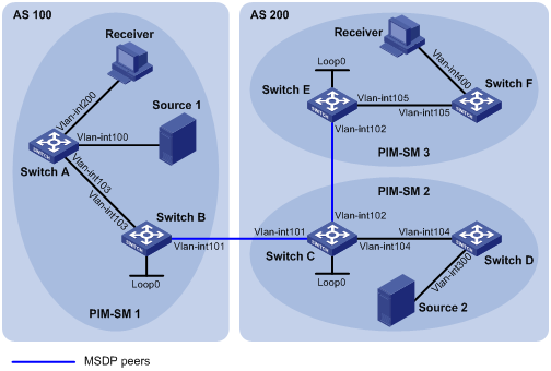
|
Device |
Interface |
IP address |
Device |
Interface |
IP address |
|
Switch A |
Vlan-int 103 |
10.110.1.2/24 |
Switch D |
Vlan-int 104 |
10.110.4.2/24 |
|
|
Vlan-int 100 |
10.110.2.1/24 |
|
Vlan-int 300 |
10.110.5.1/24 |
|
|
Vlan-int 200 |
10.110.3.1/24 |
Switch E |
Vlan-int 105 |
10.110.6.1/24 |
|
Switch B |
Vlan-int 103 |
10.110.1.1/24 |
|
Vlan-int 102 |
192.168.3.2/24 |
|
|
Vlan-int 101 |
192.168.1.1/24 |
|
Loop0 |
3.3.3.3/32 |
|
|
Loop0 |
1.1.1.1/32 |
Switch F |
Vlan-int 105 |
10.110.6.2/24 |
|
Switch C |
Vlan-int 104 |
10.110.4.1/24 |
|
Vlan-int 400 |
10.110.7.1/24 |
|
|
Vlan-int 102 |
192.168.3.1/24 |
Source 1 |
— |
10.110.2.100/24 |
|
|
Vlan-int 101 |
192.168.1.2/24 |
Source 2 |
— |
10.110.5.100/24 |
|
|
Loop0 |
2.2.2.2/32 |
|
|
|
Networking and configuration requirements
l There are two ASs in the network, AS 100 and AS 200. PIM-SM 1 belongs to AS 100 while PIM-SM 2 and PIM-SM 3 belong to AS 200. OSPF is required within each AS to ensure network-layer interoperation, and BGP is required between the two ASs to exchange routing information.
l Each PIM-SM domain has no or only one multicast source and receiver. OSPF is required within each domain for unicast routing.
l It is required that the respective Loopback 0 of Switch B, Switch C and Switch E be configured as the C-BSR and C-RP of the respective PIM-SM domains.
l It is required that an MSDP peering relationship be set up between Switch B and Switch C through EBGP, and between Switch C and Switch E through IBGP.
Applicable product matrix
|
Product |
Software version |
Hardware version |
|
S3610 Series Ethernet Switches |
Release 5301, Release 5303 |
All versions |
|
S5510 Series Ethernet Switches |
Release 5301, Release 5303 |
All versions |
|
S5500-EI Series Ethernet Switches |
Release 2102 |
All versions |
|
S7500E Series Ethernet Switches |
Release 6100, Release 6300 |
All versions |
Configuration procedure
1) Configure interface IP addresses and unicast routing for each switch
Configure an IP address and subnet mask for each interface as per Figure 1-12. Detailed configuration steps are omitted here.
Configure OSPF for interconnection between switches in each AS for network-layer interoperation, and ensure dynamic update of routing information between the switches through unicast routing. Detailed configuration steps are omitted here.
2) Enable IP multicast routing, enable PIM-SM on each interface, and configure a PIM-SM domain border
# Enable IP multicast routing on Switch A, enable PIM-SM on each interface, and enable IGMP on the host-side interface VLAN-interface 200.
<SwitchA> system-view
[SwitchA] multicast routing-enable
[SwitchA] interface vlan-interface 103
[SwitchA-Vlan-interface103] pim sm
[SwitchA-Vlan-interface103] quit
[SwitchA] interface vlan-interface 100
[SwitchA-Vlan-interface100] pim sm
[SwitchA-Vlan-interface100] quit
[SwitchA] interface vlan-interface 200
[SwitchA-Vlan-interface200] igmp enable
[SwitchA-Vlan-interface200] pim sm
[SwitchA-Vlan-interface200] quit
The configuration on Switch B, Switch C, Switch D, Switch E, and Switch F is similar to the configuration on Switch A.
# Configure a PIM domain border on Switch B.
[SwitchB] interface vlan-interface 101
[SwitchB-Vlan-interface101] pim bsr-boundary
[SwitchB-Vlan-interface101] quit
The configuration on Switch C and Switch E is similar to the configuration on Switch B.
3) Configure a C-BSR and a C-RP
# Configure Loopback 0 as a C-BSR and a C-RP on Switch B.
[SwitchB] pim
[SwitchB-pim] c-bsr loopback 0
[SwitchB-pim] c-rp loopback 0
[SwitchB-pim] quit
The configuration on Switch C and Switch E is similar to the configuration on Switch B.
4) Configure BGP for mutual route redistribution between BGP and OSPF
# Configure EBGP on Switch B, and redistribute OSPF routes.
[SwitchB] bgp 100
[SwitchB-bgp] router-id 1.1.1.1
[SwitchB-bgp] peer 192.168.1.2 as-number 200
[SwitchB-bgp] import-route ospf 1
[SwitchB-bgp] quit
# Configure IBGP and EBGP on Switch C, and redistribute OSPF routes.
[SwitchC] bgp 200
[SwitchC-bgp] router-id 2.2.2.2
[SwitchC-bgp] peer 192.168.1.1 as-number 100
[SwitchC-bgp] peer 192.168.3.2 as-number 200
[SwitchC-bgp] import-route ospf 1
[SwitchC-bgp] quit
# Configure IBGP on Switch E, and redistribute OSPF routes.
[SwitchE] bgp 200
[SwitchE-bgp] router-id 3.3.3.3
[SwitchE-bgp] peer 192.168.3.1 as-number 200
[SwitchE-bgp] import-route ospf 1
[SwitchE-bgp] quit
# Redistribute BGP routes into OSPF on Switch B.
[SwitchB] ospf 1
[SwitchB-ospf-1] import-route bgp
[SwitchB-ospf-1] quit
The configuration on Switch C and Swtich E is similar to that on Switch B. The specific configuration steps are omitted here.
5) Configure MSDP peers
# Configure an MSDP peer on Switch B.
[SwitchB] msdp
[SwitchB-msdp] peer 192.168.1.2 connect-interface vlan-interface 101
[SwitchB-msdp] quit
# Configure an MSDP peer on Switch C.
[SwitchC] msdp
[SwitchC-msdp] peer 192.168.1.1 connect-interface vlan-interface 101
[SwitchC-msdp] peer 192.168.3.2 connect-interface vlan-interface 102
[SwitchC-msdp] quit
# Configure an MSDP peer on Switch E.
[SwitchE] msdp
[SwitchE-msdp] peer 192.168.3.1 connect-interface vlan-interface 102
[SwitchE-msdp] quit
6) Verify the configuration
Use the display bgp peer command to view the BGP peering relationships between the switches. For example:
# View the information about BGP peering relationships on Switch B.
[SwitchB] display bgp peer
BGP local router ID : 1.1.1.1
Local AS number : 100
Total number of peers : 1 Peers in established state : 1
Peer V AS MsgRcvd MsgSent OutQ PrefRcv Up/Down State
192.168.1.2 4 200 24 21 0 6 00:13:09 Established
# View the information about BGP peering relationships on Switch C.
[SwitchC] display bgp peer
BGP local router ID : 2.2.2.2
Local AS number : 200
Total number of peers : 2 Peers in established state : 2
Peer V AS MsgRcvd MsgSent OutQ PrefRcv Up/Down State
192.168.1.1 4 100 18 16 0 1 00:12:04 Established
192.168.3.2 4 200 21 20 0 6 00:12:05 Established
# View the information about BGP peering relationships on Switch E.
[SwitchE] display bgp peer
BGP local router ID : 3.3.3.3
Local AS number : 200
Total number of peers : 1 Peers in established state : 1
Peer V AS MsgRcvd MsgSent OutQ PrefRcv Up/Down State
192.168.3.1 4 200 16 14 0 1 00:10:58 Established
Use the display bgp routing-table command to view the BGP routing table information on the switches. For example:
# View the BGP routing table information on Switch C.
[SwitchC] display bgp routing-table
Total Number of Routes: 13
BGP Local router ID is 2.2.2.2
Status codes: * - valid, > - best, d - damped,
h - history, i - internal, s - suppressed, S - Stale
Origin : i - IGP, e - EGP, ? - incomplete
Network NextHop MED LocPrf PrefVal Path/Ogn
*> 1.1.1.1/32 192.168.1.1 0 0 100?
*>i 2.2.2.2/32 192.168.3.2 0 100 0 ?
*> 3.3.3.3/32 0.0.0.0 0 0 ?
*> 192.168.1.0 0.0.0.0 0 0 ?
* 192.168.1.1 0 0 100?
*> 192.168.1.1/32 0.0.0.0 0 0 ?
*> 192.168.1.2/32 0.0.0.0 0 0 ?
* 192.168.1.1 0 0 100?
*> 192.168.3.0 0.0.0.0 0 0 ?
* i 192.168.3.2 0 100 0 ?
*> 192.168.3.1/32 0.0.0.0 0 0 ?
*> 192.168.3.2/32 0.0.0.0 0 0 ?
* i 192.168.3.2 0 100 0 ?
When the multicast source in PIM-SM 1 (Source 1) and the multicat source in PIM-SM 2 (Source 2) send multicast data, receivers in PIM-SM 1 and PIM-SM 3 can receive the multicast data. You can use the display msdp brief command to view the brief information of MSDP peering relationships between the switches. For example:
# View the brief information about MSDP peering relationships on Switch B.
[SwitchB] display msdp brief
MSDP Peer Brief Information
Configured Up Listen Connect Shutdown Down
1 1 0 0 0 0
Peer's Address State Up/Down time AS SA Count Reset Count
192.168.1.2 Up 00:12:27 200 13 0
# View the brief information about MSDP peering relationships on Switch C.
[SwitchC] display msdp brief
MSDP Peer Brief Information
Configured Up Listen Connect Shutdown Down
2 2 0 0 0 0
Peer's Address State Up/Down time AS SA Count Reset Count
192.168.3.2 Up 00:15:32 200 8 0
192.168.1.1 Up 00:06:39 100 13 0
# View the brief information about MSDP peering relationships on Switch E.
[SwitchE] display msdp brief
MSDP Peer Brief Information
Configured Up Listen Connect Shutdown Down
1 1 0 0 0 0
Peer's Address State Up/Down time AS SA Count Reset Count
192.168.3.1 Up 01:07:08 200 8 0
# View the detailed MSDP peer information on Switch B.
[SwitchB] display msdp peer-status
MSDP Peer 192.168.1.2, AS 200
Description:
Information about connection status:
State: Up
Up/down time: 00:15:47
Resets: 0
Connection interface: Vlan-interface101 (192.168.1.1)
Number of sent/received messages: 16/16
Number of discarded output messages: 0
Elapsed time since last connection or counters clear: 00:17:51
Information about (Source, Group)-based SA filtering policy:
Import policy: none
Export policy: none
Information about SA-Requests:
Policy to accept SA-Request messages: none
Sending SA-Requests status: disable
Minimum TTL to forward SA with encapsulated data: 0
SAs learned from this peer: 0, SA-cache maximum for the peer: none
Input queue size: 0, Output queue size: 0
Counters for MSDP message:
Count of RPF check failure: 0
Incoming/outgoing SA messages: 0/0
Incoming/outgoing SA requests: 0/0
Incoming/outgoing SA responses: 0/0
Incoming/outgoing data packets: 0/0
Complete configuration
1) Configuration on Switch A
#
multicast routing-enable
#
interface Vlan-interface100
ip address 10.110.2.1 255.255.255.0
pim sm
#
interface Vlan-interface103
ip address 10.110.1.2 255.255.255.0
pim sm
#
interface Vlan-interface200
ip address 10.110.3.1 255.255.255.0
igmp enable
pim sm
#
ospf 1
area 0.0.0.0
network 10.110.1.0 0.0.0.255
network 10.110.2.0 0.0.0.255
network 10.110.3.0 0.0.0.255
#
2) Configuration on Switch B
#
multicast routing-enable
#
interface LoopBack0
ip address 1.1.1.1 255.255.255.255
pim sm
#
interface Vlan-interface101
ip address 192.168.1.1 255.255.255.0
pim bsr-boundary
pim sm
#
interface Vlan-interface103
ip address 10.110.1.1 255.255.255.0
pim sm
#
bgp 100
router-id 1.1.1.1
import-route ospf 1
undo synchronization
peer 192.168.1.2 as-number 200
#
ospf 1
import-route bgp
area 0.0.0.0
network 192.168.1.0 0.0.0.255
network 10.110.1.0 0.0.0.255
network 1.1.1.1 0.0.0.0
#
pim
c-bsr LoopBack0
c-rp LoopBack0
#
msdp
peer 192.168.1.2 connect-interface vlan-interface 101
#
3) Configuration on Switch C
#
multicast routing-enable
#
interface LoopBack0
ip address 2.2.2.2 255.255.255.255
pim sm
#
interface Vlan-interface101
ip address 192.168.1.2 255.255.255.0
pim bsr-boundary
pim sm
#
interface Vlan-interface102
ip address 192.168.3.1 255.255.255.0
pim sm
#
interface Vlan-interface104
ip address 10.110.4.1 255.255.255.0
pim sm
#
bgp 100
router-id 2.2.2.2
import-route ospf 1
undo synchronization
peer 192.168.1.1 as-number 100
peer 192.168.3.2 as-number 200
#
ospf 1
import-route bgp
area 0.0.0.0
network 192.168.1.0 0.0.0.255
network 192.168.3.0 0.0.0.255
network 10.110.4.1 0.0.0.255
network 2.2.2.2 0.0.0.0
#
pim
c-bsr LoopBack0
c-rp LoopBack0
#
msdp
peer 192.168.1.1 connect-interface vlan-interface 101
peer 192.168.3.2 connect-interface vlan-interface 102
#
4) Configuration on Switch D
#
multicast routing-enable
#
interface Vlan-interface104
ip address 10.110.4.2 255.255.255.0
pim sm
#
interface Vlan-interface300
ip address 10.110.5.1 255.255.255.0
pim sm
#
5) Configuration on Switch E
#
multicast routing-enable
#
interface LoopBack0
ip address 3.3.3.3 255.255.255.255
pim sm
#
interface Vlan-interface102
ip address 192.168.3.2 255.255.255.0
pim bsr-boundary
pim sm
#
interface Vlan-interface105
ip address 10.110.6.1 255.255.255.0
pim sm
#
bgp 100
router-id 3.3.3.3
import-route ospf 1
undo synchronization
peer 192.168.3.1 as-number 200
#
ospf 1
import-route bgp
area 0.0.0.0
network 192.168.3.0 0.0.0.255
network 10.110.6.1 0.0.0.255
network 3.3.3.3 0.0.0.0
#
pim
c-bsr LoopBack0
c-rp LoopBack0
#
msdp
peer 192.168.3.1 connect-interface vlan-interface 102
#
6) Configuration on Switch F
#
multicast routing-enable
#
interface Vlan-interface105
ip address 10.110.6.2 255.255.255.0
pim sm
#
interface Vlan-interface400
ip address 10.110.7.1 255.255.255.0
pim sm
igmp enable
#
Configuration guildlines
l MSDP is applicable only if the intra-domain multicast routing protocol is PIM-SM.
l MSDP is meaningful only for the any-source multicast (ASM) model.
Configuring Inter-Domain Multicast Leveraging Static RPF Peers
Network diagram
Figure 1-13 Network diagram for configuration of inter-domain multicast leveraging static RPF peers
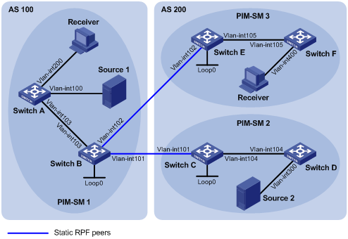
|
Device |
Interface |
IP address |
Device |
Interface |
IP address |
|
Switch A |
Vlan-int 103 |
10.110.1.2/24 |
Switch D |
Vlan-int 104 |
10.110.4.2/24 |
|
|
Vlan-int 100 |
10.110.2.1/24 |
|
Vlan-int 300 |
10.110.5.1/24 |
|
|
Vlan-int 200 |
10.110.3.1/24 |
Switch E |
Vlan-int 105 |
10.110.6.1/24 |
|
Switch B |
Vlan-int 103 |
10.110.1.1/24 |
|
Vlan-int 102 |
192.168.3.2/24 |
|
|
Vlan-int 101 |
192.168.1.1/24 |
|
Loop0 |
3.3.3.3/32 |
|
|
Vlan-int 102 |
192.168.3.1/24 |
Switch F |
Vlan-int 105 |
10.110.6.2/24 |
|
|
Loop 0 |
1.1.1.1/32 |
|
Vlan-int 400 |
10.110.7.1/24 |
|
Switch C |
Vlan-int 101 |
192.168.1.2/24 |
Source 1 |
— |
10.110.2.100/24 |
|
|
Vlan-int 104 |
10.110.4.1/24 |
Source 2 |
— |
10.110.5.100/24 |
|
|
Loop 0 |
2.2.2.2/32 |
|
|
|
Networking and configuration requirements
l There are two ASs in the network, AS 100 and AS 200. PIM-SM 1 belongs to AS 100 while PIM-SM 2 and PIM-SM 3 belong to AS 200. OSPF is required within each AS to ensure network-layer interoperation, and BGP is required between the two ASs to exchange routing information.
l Each PIM-SM domain has no or only one multicast source and receiver. OSPF is required within each domain for unicast routing.
l PIM-SM 2 and PIM-SM 3 are both stub domains, and BGP or MBGP is not required between these two domains and PIM-SM 1. Instead, static RPF peers are configured to avoid RPF check on SA messages.
l It is required that the respective Loopback 0 of Switch B, Switch C and Switch E be configured as the C-BSR and C-RP of the respective PIM-SM domains.
l It is required that Switch C and Switch E be configured as static RPF peers of Switch B, and Switch B be configured as the only static RPF peer of Switch C and Switch E, so that any switch can receive SA messages only from its static RPF peer(s) and permitted by the corresponding filtering policy.
Applicable product matrix
|
Product |
Software version |
Hardware version |
|
S3610 Series Ethernet Switches |
Release 5301, Release 5303 |
All versions |
|
S5510 Series Ethernet Switches |
Release 5301, Release 5303 |
All versions |
|
S5500-EI Series Ethernet Switches |
Release 2102 |
All versions |
|
S7500E Series Ethernet Switches |
Release 6100, Release 6300 |
All versions |
Configuration procedure
1) Configure interface IP addresses and unicast routing for each switch
Configure an IP address and subnet mask for each interface as per Figure 1-13. Detailed configuration steps are omitted here.
Configure OSPF for interconnection between the switches for network-layer interoperation, and ensure dynamic update of routing information among the switches through unicast routing. Detailed configuration steps are omitted here.
2) Enable IP multicast routing, enable PIM-SM and IGMP, and configure a PIM-SM domain border
# Enable IP multicast routing on Switch A, enable PIM-SM on each interface, and enable IGMP on the host-side interface VLAN-interface 200.
<SwitchA> system-view
[SwitchA] multicast routing-enable
[SwitchA] interface vlan-interface 103
[SwitchA-Vlan-interface103] pim sm
[SwitchA-Vlan-interface103] quit
[SwitchA] interface vlan-interface 100
[SwitchA-Vlan-interface100] pim sm
[SwitchA-Vlan-interface100] quit
[SwitchA] interface vlan-interface 200
[SwitchA-Vlan-interface200] igmp enable
[SwitchA-Vlan-interface200] pim sm
[SwitchA-Vlan-interface200] quit
The configuration on Switch B, Switch C, Switch D, Switch E, and Switch F is similar to the configuration on Switch A.
# Configure PIM domain boundary on Switch B.
[SwitchB] interface vlan-interface 102
[SwitchB-Vlan-interface102] pim bsr-boundary
[SwitchB-Vlan-interface102] quit
[SwitchB] interface vlan-interface 101
[SwitchB-Vlan-interface101] pim bsr-boundary
[SwitchB-Vlan-interface101] quit
The configuration on Switch C and Switch E is similar to the configuration on Switch B.
3) Configure a C-BSR and a C-RP
# Configure Loopback 0 as a C-BSR and a C-RP on Switch B.
[SwitchB] pim
[SwitchB-pim] c-bsr loopback 0
[SwitchB-pim] c-rp loopback 0
[SwitchB-pim] quit
The configuration on Switch C and Switch E is similar to the configuration on Switch B.
4) Configure a static RPF peer
# Configure Switch C and Switch E as MSDP peers and static RPF peers of Switch B.
[SwitchB] ip ip-prefix list-df permit 192.168.0.0 16 greater-equal 16 less-equal 32
[SwitchB] msdp
[SwitchB-msdp] peer 192.168.3.2 connect-interface vlan-interface 102
[SwitchB-msdp] peer 192.168.1.2 connect-interface vlan-interface 101
[SwitchB-msdp] static-rpf-peer 192.168.3.2 rp-policy list-df
[SwitchB-msdp] static-rpf-peer 192.168.1.2 rp-policy list-df
[SwitchB-msdp] quit
# Configure Switch B as an MSDP peer and a static RPF peer of Switch C.
[SwitchC] ip ip-prefix list-c permit 192.168.0.0 16 greater-equal 16 less-equal 32
[SwitchC] msdp
[SwitchC-msdp] peer 192.168.1.1 connect-interface vlan-interface 101
[SwitchC-msdp] static-rpf-peer 192.168.1.1 rp-policy list-c
[SwitchC-msdp] quit
# Configure Switch B as an MSDP peer and a static RPF peer of Switch E.
[SwitchE] ip ip-prefix list-c permit 192.168.0.0 16 greater-equal 16 less-equal 32
[SwitchE] msdp
[SwitchE-msdp] peer 192.168.3.1 connect-interface vlan-interface 102
[SwitchE-msdp] static-rpf-peer 192.168.3.1 rp-policy list-c
[SwitchE-msdp] quit
5) Verify the configuration
Use the display bgp peer command to view the BGP peering relationships between the switches. If the command gives no output information, a BGP peering relationship has not been established between the switches.
When the multicast source in PIM-SM 1 (Source 1) and the multicast soruce in PIM-SM 2 (Source 2) send multicast data, receivers in PIM-SM 1 and PIM-SM 3 can receive the multicast data. You can use the display msdp brief command to view the brief information of MSDP peering relationships between the switches. For example:
# View the brief MSDP peer information on Switch B.
[SwitchB] display msdp brief
MSDP Peer Brief Information
Configured Up Listen Connect Shutdown Down
2 2 0 0 0 0
Peer's Address State Up/Down time AS SA Count Reset Count
192.168.3.2 Up 01:07:08 ? 8 0
192.168.1.2 Up 00:16:39 ? 13 0
# View the brief MSDP peer information on Switch C.
[SwitchC] display msdp brief
MSDP Peer Brief Information
Configured Up Listen Connect Shutdown Down
1 1 0 0 0 0
Peer's Address State Up/Down time AS SA Count Reset Count
192.168.1.1 Up 01:07:09 ? 8 0
# View the brief MSDP peer information on Switch E.
[SwitchE] display msdp brief
MSDP Peer Brief Information
Configured Up Listen Connect Shutdown Down
1 1 0 0 0 0
Peer's Address State Up/Down time AS SA Count Reset Count
192.168.3.1 Up 00:16:40 ? 13 0
Complete configuration
1) Configuration on Switch A
#
multicast routing-enable
#
interface Vlan-interface100
ip address 10.110.2.1 255.255.255.0
pim sm
#
interface Vlan-interface103
ip address 10.110.1.2 255.255.255.0
pim sm
#
interface Vlan-interface200
ip address 10.110.3.1 255.255.255.0
igmp enable
pim sm
#
ospf 1
area 0.0.0.0
network 10.110.1.0 0.0.0.255
network 10.110.2.0 0.0.0.255
network 10.110.3.0 0.0.0.255
#
2) Configuration on Switch B
#
multicast routing-enable
#
interface LoopBack0
ip address 1.1.1.1 255.255.255.255
pim sm
#
interface Vlan-interface101
ip address 192.168.1.1 255.255.255.0
pim bsr-boundary
pim sm
#
interface Vlan-interface102
ip address 192.168.3.1 255.255.255.0
pim bsr-boundary
pim sm
#
interface Vlan-interface103
ip address 10.110.1.1 255.255.255.0
pim sm
#
ospf 1
area 0.0.0.0
network 192.168.1.0 0.0.0.255
network 10.110.1.0 0.0.0.255
network 1.1.1.1 0.0.0.0
#
pim
c-bsr LoopBack0
c-rp LoopBack0
#
msdp
peer 192.168.3.2 connect-interface vlan-interface 102
peer 192.168.1.2 connect-interface vlan-interface 101
static-rpf-peer 192.168.3.2 rp-policy list-df
static-rpf-peer 192.168.1.2 rp-policy list-df
#
ip ip-prefix list-df index 10 permit 192.168.0.0 16 greater-equal 16 less-equal
32
#
3) Configuration on Switch C
#
multicast routing-enable
#
interface LoopBack0
ip address 2.2.2.2 255.255.255.255
pim sm
#
interface Vlan-interface101
ip address 192.168.1.2 255.255.255.0
pim bsr-boundary
pim sm
#
interface Vlan-interface104
ip address 10.110.4.1 255.255.255.0
pim sm
#
ospf 1
area 0.0.0.0
network 192.168.1.0 0.0.0.255
network 10.110.4.1 0.0.0.255
network 2.2.2.2 0.0.0.0
#
pim
c-bsr LoopBack0
c-rp LoopBack0
#
msdp
peer 192.168.1.1 connect-interface vlan-interface 101
static-rpf-peer 192.168.1.1 rp-policy list-c
#
ip ip-prefix list-c permit 192.168.0.0 16 greater-equal 16 less-equal 32
#
4) Configuration on Switch D
#
multicast routing-enable
#
interface Vlan-interface104
ip address 10.110.4.2 255.255.255.0
pim sm
#
interface Vlan-interface300
ip address 10.110.5.1 255.255.255.0
pim sm
#
5) Configuration on Switch E
#
multicast routing-enable
#
interface LoopBack0
ip address 3.3.3.3 255.255.255.255
pim sm
#
interface Vlan-interface102
ip address 192.168.3.2 255.255.255.0
pim bsr-boundary
pim sm
#
interface Vlan-interface105
ip address 10.110.6.1 255.255.255.0
pim sm
#
ospf 1
area 0.0.0.0
network 192.168.3.0 0.0.0.255
network 10.110.6.1 0.0.0.255
network 3.3.3.3 0.0.0.0
#
pim
c-bsr LoopBack0
c-rp LoopBack0
#
msdp
peer 192.168.3.1 connect-interface vlan-interface 102
static-rpf-peer 192.168.3.1 rp-policy list-c
#
ip ip-prefix list-c permit 192.168.0.0 16 greater-equal 16 less-equal 32
#
6) Configuration on Switch F
#
multicast routing-enable
#
interface Vlan-interface105
ip address 10.110.6.2 255.255.255.0
pim sm
#
interface Vlan-interface400
ip address 10.110.7.1 255.255.255.0
pim sm
igmp enable
#
Configuration guildlines
None.
Configuring Anycast RP
Network diagram
Figure 1-14 Network diagram for anycast RP configuration
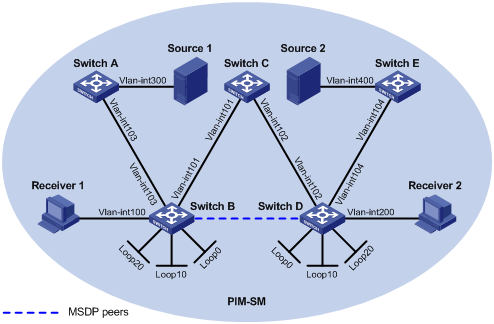
|
Device |
Interface |
IP address |
Device |
Interface |
IP address |
|
Source 1 |
— |
10.110.5.100/24 |
Switch C |
Vlan-int 101 |
192.168.1.2/24 |
|
Source 2 |
— |
10.110.6.100/24 |
|
Vlan-int 102 |
192.168.2.2/24 |
|
Switch A |
Vlan-int 300 |
10.110.5.1/24 |
Switch D |
Vlan-int 200 |
10.110.3.1/24 |
|
|
Vlan-int 103 |
10.110.2.2/24 |
|
Vlan-int 104 |
10.110.4.1/24 |
|
Switch B |
Vlan-int 100 |
10.110.1.1/24 |
|
Vlan-int 102 |
192.168.2.1/24 |
|
|
Vlan-int 103 |
10.110.2.1/24 |
|
Loop 0 |
2.2.2.2/32 |
|
|
Vlan-int 101 |
192.168.1.1/24 |
|
Loop 10 |
4.4.4.4/32 |
|
|
Loop 0 |
1.1.1.1/32 |
|
Loop 20 |
10.1.1.1/32 |
|
|
Loop 10 |
3.3.3.3/32 |
Switch E |
Vlan-int 400 |
10.110.6.1/24 |
|
|
Loop 20 |
10.1.1.1/32 |
|
Vlan-int 104 |
10.110.4.2/24 |
Networking and configuration requirements
l The PIM-SM domain has multiple multicast sources and receivers. OSPF is required within the domain to provide unicast routing.
l It is required to configure the anycast RP application so that the receiver-side DRs and the source-side DRs can initiate a join or register message to their respective RPs that are the topologically nearest to them.
l On Switch B and Switch D, configure Loopback 10 as a C-BSR and Loopback 20 as a C-RP.
l The router ID of Switch B is 1.1.1.1, while the router ID of Switch D is 2.2.2.2. Set up an MSDP peering relationship between Switch B and Switch D.
Applicable product matrix
|
Product |
Software version |
Hardware version |
|
S3610 Series Ethernet Switches |
Release 5301, Release 5303 |
All versions |
|
S5510 Series Ethernet Switches |
Release 5301, Release 5303 |
All versions |
|
S5500-EI Series Ethernet Switches |
Release 2102 |
All versions |
|
S7500E Series Ethernet Switches |
Release 6100, Release 6300 |
All versions |
Configuration procedure
1) Configure interface IP addresses and unicast routing for each switch
Configure an IP address and subnet mask for each interface as per Figure 1-14. Detailed configuration steps are omitted here.
Configure OSPF for interconnection between the switches for network-layer interoperation, and ensure dynamic update of routing information between the switches through unicast routing. Detailed configuration steps are omitted here.
2) Enable IP multicast routing, and enable PIM-SM and IGMP
# Enable IP multicast routing on Switch B, enable PIM-SM on each interface, and enable IGMP on the host-side interface VLAN-interface 100.
3) Configuration on Switch B
<SwitchB> system-view
[SwitchB] multicast routing-enable
[SwitchB] interface vlan-interface 100
[SwitchB-Vlan-interface100] igmp enable
[SwitchB-Vlan-interface100] pim sm
[SwitchB-Vlan-interface100] quit
[SwitchB] interface vlan-interface 103
[SwitchB-Vlan-interface103] pim sm
[SwitchB-Vlan-interface103] quit
[SwitchB] interface Vlan-interface 101
[SwitchB-Vlan-interface101] pim sm
[SwitchB-Vlan-interface101] quit
[SwitchB] interface loopback 0
[SwitchB-LoopBack0] pim sm
[SwitchB-LoopBack0] quit
[SwitchB] interface loopback 10
[SwitchB-LoopBack10] pim sm
[SwitchB-LoopBack10] quit
[SwitchB] interface loopback 20
[SwitchB-LoopBack20] pim sm
[SwitchB-LoopBack20] quit
The configuration on Switch A, Switch C, Switch D, and Switch E is similar to the configuration on Switch B.
4) Configure a C-BSR and a C-RP
# Configure Loopback 10 as a C-BSR and Loopback 20 as a C-RP on Switch B.
[SwitchB] pim
[SwitchB-pim] c-bsr loopback 10
[SwitchB-pim] c-rp loopback 20
[SwitchB-pim] quit
The configuration on Switch D is similar to the configuration on Switch B.
5) Configure an MSDP peer
# Configure an MSDP peer on Loopback 0 of Switch B.
[SwitchB] msdp
[SwitchB-msdp] originating-rp loopback 0
[SwitchB-msdp] peer 2.2.2.2 connect-interface loopback 0
[SwitchB-msdp] quit
# Configure an MSDP peer on Loopback 0 of Switch D.
[SwitchD] msdp
[SwitchD-msdp] originating-rp loopback 0
[SwitchD-msdp] peer 1.1.1.1 connect-interface loopback 0
[SwitchD-msdp] quit
6) Verify the configuration
You can use the display msdp brief command to view the brief information of MSDP peering relationships between the switches.
# View the brief MSDP peer information on Switch B.
[SwitchB] display msdp brief
MSDP Peer Brief Information
Configured Up Listen Connect Shutdown Down
1 1 0 0 0 0
Peer's Address State Up/Down time AS SA Count Reset Count
2.2.2.2 Up 00:10:17 ? 0 0
# View the brief MSDP peer information on Switch D.
[SwitchD] display msdp brief
MSDP Peer Brief Information
Configured Up Listen Connect Shutdown Down
1 1 0 0 0 0
Peer's Address State Up/Down time AS SA Count Reset Count
1.1.1.1 Up 00:10:18 ? 0 0
Use the display pim routing-table command to view the PIM routing information on the switches.
When Source 1 (10.110.5.100/24) sends multicast data to multicast group G (225.1.1.1), Receiver 1 joins multicast group G. By comparing the PIM routing information displayed on Switch B with that displayed on Switch D, you can see that Switch B acts as the RP for Source 1 and Receiver 1.
# View the PIM routing information on Switch B.
[SwitchB] display pim routing-table
Total 1 (*, G) entry; 1 (S, G) entry
(*, 225.1.1.1)
RP: 10.1.1.1 (local)
Protocol: pim-sm, Flag: WC
UpTime: 00:15:04
Upstream interface: Register
Upstream neighbor: NULL
RPF prime neighbor: NULL
Downstream interface(s) information:
Total number of downstreams: 1
1: Vlan-interface100
Protocol: igmp, UpTime: 00:15:04, Expires: -
(10.110.5.100, 225.1.1.1)
RP: 10.1.1.1 (local)
Protocol: pim-sm, Flag: SPT 2MSDP ACT
UpTime: 00:46:28
Upstream interface: Vlan-interface103
Upstream neighbor: 10.110.2.2
RPF prime neighbor: 10.110.2.2
Downstream interface(s) information:
Total number of downstreams: 1
1: Vlan-interface100
Protocol: pim-sm, UpTime: - , Expires: -
# View the PIM routing information on Switch D.
[SwitchD] display pim routing-table
No information is output on Switch D.
Receiver 1 has left multicast group G. Source 1 has stopped sending multicast data to multicast group G. When Source 2 (10.110.6.100/24) sends multicast data to G, Receiver 2 joins G. By comparing the PIM routing information displayed on Switch B with that displayed on Switch D, you can see that Switch D acts as the RP for Source 2 and Receiver 2.
# View the PIM routing information on Switch B.
[SwitchB] display pim routing-table
No information is output on Switch B.
# View the PIM routing information on Switch D.
[SwitchD] display pim routing-table
Total 1 (*, G) entry; 1 (S, G) entry
(*, 225.1.1.1)
RP: 10.1.1.1 (local)
Protocol: pim-sm, Flag: WC
UpTime: 00:12:07
Upstream interface: Register
Upstream neighbor: NULL
RPF prime neighbor: NULL
Downstream interface(s) information:
Total number of downstreams: 1
1: Vlan-interface200
Protocol: igmp, UpTime: 00:12:07, Expires: -
(10.110.6.100, 225.1.1.1)
RP: 10.1.1.1 (local)
Protocol: pim-sm, Flag: SPT 2MSDP ACT
UpTime: 00:40:22
Upstream interface: Vlan-interface104
Upstream neighbor: 10.110.4.2
RPF prime neighbor: 10.110.4.2
Downstream interface(s) information:
Total number of downstreams: 1
1: Vlan-interface200
Protocol: pim-sm, UpTime: - , Expires: -
Complete configuration
1) Configuration on Switch A
#
multicast routing-enable
#
interface Vlan-interface103
ip address 10.110.2.2 255.255.255.0
pim sm
#
interface Vlan-interface200
ip address 10.110.5.1 255.255.255.0
igmp enable
pim sm
#
ospf 1
area 0.0.0.0
network 10.110.2.0 0.0.0.255
network 10.110.5.0 0.0.0.255
#
2) Configuration on Switch B
#
multicast routing-enable
#
interface LoopBack0
ip address 1.1.1.1 255.255.255.255
pim sm
#
interface LoopBack10
ip address 3.3.3.3 255.255.255.255
pim sm
#
interface LoopBack20
ip address 10.1.1.1 255.255.255.255
pim sm
#
interface Vlan-interface100
ip address 10.110.1.1 255.255.255.0
pim sm
#
interface Vlan-interface101
ip address 192.168.1.1 255.255.255.0
pim sm
#
interface Vlan-interface103
ip address 10.110.2.1 255.255.255.0
pim sm
#
ospf 1
area 0.0.0.0
network 192.168.1.0 0.0.0.255
network 10.110.1.0 0.0.0.255
network 10.110.2.0 0.0.0.255
network 1.1.1.1 0.0.0.0
network 3.3.3.3 0.0.0.0
network 10.1.1.1 0.0.0.0
#
pim
c-bsr LoopBack10
c-rp LoopBack20
#
msdp
originating-rp loopback 0
peer 2.2.2.2 connect-interface loopback 0
#
3) Configuration on Switch C
#
multicast routing-enable
#
interface Vlan-interface101
ip address 192.168.1.2 255.255.255.0
pim sm
#
interface Vlan-interface102
ip address 192.168.2.2 255.255.255.0
pim sm
#
ospf 1
area 0.0.0.0
network 192.168.1.0 0.0.0.255
network 192.168.2.0 0.0.0.255
#
4) Configuration on Switch D
#
multicast routing-enable
#
interface LoopBack0
ip address 2.2.2.2 255.255.255.255
pim sm
#
interface LoopBack10
ip address 4.4.4.4 255.255.255.255
pim sm
#
interface LoopBack20
ip address 10.1.1.1 255.255.255.255
pim sm
#
interface Vlan-interface102
ip address 192.168.2.1 255.255.255.0
pim sm
#
interface Vlan-interface104
ip address 10.110.4.1 255.255.255.0
pim sm
#
interface Vlan-interface200
ip address 10.110.3.1 255.255.255.0
pim sm
#
ospf 1
area 0.0.0.0
network 192.168.2.0 0.0.0.255
network 10.110.4.0 0.0.0.255
network 10.110.3.0 0.0.0.255
network 2.2.2.2 0.0.0.0
network 4.4.4.4 0.0.0.0
network 10.1.1.1 0.0.0.0
#
pim
c-bsr LoopBack10
c-rp LoopBack20
#
msdp
originating-rp loopback 0
peer 1.1.1.1 connect-interface loopback 0
#
5) Configuration on Switch E
#
multicast routing-enable
#
interface Vlan-interface104
ip address 10.110.4.2 255.255.255.0
pim sm
#
interface Vlan-interface400
ip address 10.110.6.1 255.255.255.0
pim sm
igmp enable
#
Configuration guildlines
l Be sure to configure a 32-bit subnet mask (255.255.255.255) for the anycast RP address, namely configure the anycast RP address into a host address.
l An MSDP peer address must be different from the anycast RP address.
Multicast Routing and Forwarding Configuration Example
Changing an RPF Route
Network diagram
Figure 1-15 Network diagram for RPF route configuration
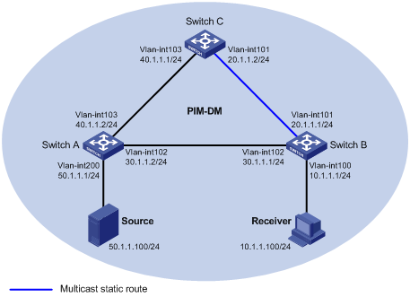
Networking and configuration requirements
PIM-DM is required in the network, in which all the switches support multicast. Switch A, Switch B and Switch C are required to run OSPF. Typically, Receiver can receive the multicast data from Source through the path Switch A—Switch B, which is the same as the unicast route. Perform the following configuration so that Receiver can receive the multicast data from Source through the path Switch A—Switch C—Switch B, which is different from the unicast route.
Applicable product matrix
|
Product |
Software version |
Hardware version |
|
S3610 Series Ethernet Switches |
Release 5301, Release 5303 |
All versions |
|
S5510 Series Ethernet Switches |
Release 5301, Release 5303 |
All versions |
|
S5500-EI Series Ethernet Switches |
Release 2102 |
All versions |
|
S7500E Series Ethernet Switches |
Release 6100, Release 6300 |
All versions |
Configuration procedure
1) Configure interface IP addresses and unicast routing for each switch
Configure an IP address and subnet mask for each interface as per Figure 1-15. The detailed configuration steps are omitted here.
Enable OSPF on the switches in the PIM-DM domain for network-layer interoperation, and enable the switches to dynamically update their routing information by leveraging unicast routing. The specific configuration steps are omitted here.
2) Enable IP multicast routing, and enable PIM-DM and IGMP
# Enable IP multicast routing on Switch B, enable PIM-DM on each interface, and enable IGMP on the Vlan-interface100.
<SwitchB> system-view
[SwitchB] multicast routing-enable
[SwitchB] interface vlan-interface 100
[SwitchB-Vlan-interface100] igmp enable
[SwitchB-Vlan-interface100] pim dm
[SwitchB-Vlan-interface100] quit
[SwitchB] interface vlan-interface 101
[SwitchB-Vlan-interface101] pim dm
[SwitchB-Vlan-interface101] quit
[SwitchB] interface vlan-interface 102
[SwitchB-Vlan-interface102] pim dm
[SwitchB-Vlan-interface102] quit
# Enable IP multicast routing on Switch A, and enable PIM-DM on each interface.
<SwitchA> system-view
[SwitchA] multicast routing-enable
[SwitchA] interface vlan-interface 200
[SwitchA-Vlan-interface200] pim dm
[SwitchA-Vlan-interface200] quit
[SwitchA] interface vlan-interface 102
[SwitchA-Vlan-interface102] pim dm
[SwitchA-Vlan-interface102] quit
[SwitchA] interface vlan-interface 103
[SwitchA-Vlan-interface103] pim dm
[SwitchA-Vlan-interface103] quit
The configuration on Switch C is similar to the configuration on Switch A.
# Use the display multicast rpf-info command to view the RPF route to Source on Switch B.
[SwitchB] display multicast rpf-info 50.1.1.100
RPF information about source 50.1.1.100:
RPF interface: Vlan-interface102, RPF neighbor: 30.1.1.2
Referenced route/mask: 50.1.1.0/24
Referenced route type: igp
Route selection rule: preference-preferred
Load splitting rule: disable
As shown above, the current RPF route on Switch B is contributed by unicast routing and the RPF neighbor is Switch A.
3) Configure a multicast static route
# Configure a multicast static route on Switch B so that Switch C becomes the RPF neighbor to Source.
[SwitchB] ip rpf-route-static 50.1.1.100 24 20.1.1.2
4) Verify the configuration
# Use the display multicast rpf-info command to view the information about the RPF route to Source on Switch B.
[SwitchB] display multicast rpf-info 50.1.1.100
RPF information about source 50.1.1.100:
RPF interface: Vlan-interface101, RPF neighbor: 20.1.1.2
Referenced route/mask: 50.1.1.0/24
Referenced route type: multicast static
Route selection rule: preference-preferred
Load splitting rule: disable
As shown above, the RPF route on Switch B has changed to the configured multicast static route, and the RPF neighbor is now Switch C.
Complete configuration
1) Configuration on Switch A
#
multicast routing-enable
#
interface Vlan-interface102
ip address 30.1.1.2 255.255.255.0.
pim dm
#
interface Vlan-interface103
ip address 40.1.1.2 255.255.255.0
pim dm
#
interface Vlan-interface200
ip address 50.1.1.1 255.255.255.0
pim dm
#
2) Configuration on Switch B
#
multicast routing-enable
#
interface Vlan-interface100
ip address 10.1.1.1 255.255.255.0.
igmp enable
pim dm
#
interface Vlan-interface101
ip address 20.1.1.1 255.255.255.0.
pim dm
#
interface Vlan-interface102
ip address 30.1.1.1 255.255.255.0
pim dm
#
ip rpf-route-static 50.1.1.0 24 20.1.1.2
#
3) Configuration on Switch C
#
multicast routing-enable
#
interface Vlan-interface101
ip address 20.1.1.2 255.255.255.0.
pim dm
#
interface Vlan-interface103
ip address 40.1.1.1 255.255.255.0
pim dm
#
Configuration guildlines
None.
Creating an RPF Route
Network diagram
Figure 1-16 Network diagram for RPF route creation
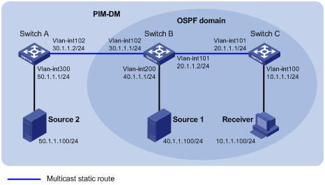
Networking and configuration requirements
PIM-DM is required in the network, in which all the switches support IP multicast. Switch B and Switch C run OSPF, and are unicast isolated from Switch A. Typically, Receiver can receive the multicast data from Source 1 in the OSPF domain. Perform the following configuration so that Receiver can receive multicast data from Source 2, which is outside the OSPF domain.
Applicable product matrix
|
Product |
Software version |
Hardware version |
|
S3610 Series Ethernet Switches |
Release 5301, Release 5303 |
All versions |
|
S5510 Series Ethernet Switches |
Release 5301, Release 5303 |
All versions |
|
S5500-EI Series Ethernet Switches |
Release 2102 |
All versions |
|
S7500E Series Ethernet Switches |
Release 6100, Release 6300 |
All versions |
Configuration procedure
1) Configure interface IP addresses and unicast routing for each switch
Configure an IP address and subnet mask for each interface as per Figure 1-16. The detailed configuration steps are omitted here.
Enable OSPF on Switch B and Switch C for network-layer interoperation between them, and enable the switches to dynamically update their routing information by leveraging the unicast routing protocol. The specific configuration steps are omitted here.
2) Enable IP multicast routing, and enable PIM-DM and IGMP
# Enable IP multicast routing on Switch C, enable PIM-DM on each interface, and enable IGMP on the host-side interface VLAN-interface 100.
<SwitchC> system-view
[SwitchC] multicast routing-enable
[SwitchC] interface vlan-interface 100
[SwitchC-Vlan-interface100] igmp enable
[SwitchC-Vlan-interface100] pim dm
[SwitchC-Vlan-interface100] quit
[SwitchC] interface vlan-interface 101
[SwitchC-Vlan-interface101] pim dm
[SwitchC-Vlan-interface101] quit
# Enable IP multicast routing on Switch A and enable PIM-DM on each interface.
<SwitchA> system-view
[SwitchA] multicast routing-enable
[SwitchC] interface vlan-interface 300
[SwitchC-Vlan-interface300] pim dm
[SwitchC-Vlan-interface300] quit
[SwitchC] interface vlan-interface 102
[SwitchC-Vlan-interface102] pim dm
[SwitchC-Vlan-interface102] quit
The configuration on Switch B is similar to that on Switch A.
# Use the display multicast rpf-info command to view the RPF routes to Source 2 on Switch B and Switch C.
[SwitchB] display multicast rpf-info 50.1.1.100
[SwitchC] display multicast rpf-info 50.1.1.100
No information is displayed. This means that no RPF route to Source 2 exists on Switch B and Switch C.
3) Configure a multicast static route
# Configure a multicast static route on Switch B, specifying Switch A as its RPF neighbor on the route to Source 2.
[SwitchB] ip rpf-route-static 50.1.1.100 24 30.1.1.2
# Configure a multicast static route on Switch C, specifying Switch B as its RPF neighbor on the route to Source 2.
[SwitchC] ip rpf-route-static 50.1.1.100 24 20.1.1.2
4) Verify the configuration
# Use the display multicast rpf-info command to view the RPF routes to Source 2 on Switch B and Switch C.
[SwitchB] display multicast rpf-info 50.1.1.100
RPF information about source 50.1.1.100:
RPF interface: Vlan-interface102, RPF neighbor: 30.1.1.2
Referenced route/mask: 50.1.1.0/24
Referenced route type: multicast static
Route selection rule: preference-preferred
Load splitting rule: disable
[SwitchC] display multicast rpf-info 50.1.1.100
RPF information about source 50.1.1.100:
RPF interface: Vlan-interface101, RPF neighbor: 20.1.1.2
Referenced route/mask: 50.1.1.0/24
Referenced route type: multicast static
Route selection rule: preference-preferred
Load splitting rule: disable
As shown above, the static RPF routes to Source 2 exist on Switch B and Switch C.
Complete configuration
1) Configuration on Switch A
#
multicast routing-enable
#
interface Vlan-interface102
ip address 30.1.1.2 255.255.255.0.
pim dm
#
interface Vlan-interface300
ip address 50.1.1.1 255.255.255.0
pim dm
#
2) Configuration on Switch B
#
multicast routing-enable
#
interface Vlan-interface101
ip address 20.1.1.2 255.255.255.0.
pim dm
#
interface Vlan-interface102
ip address 30.1.1.1 255.255.255.0
pim dm
#
interface Vlan-interface200
ip address 40.1.1.1 255.255.255.0.
pim dm
#
ip rpf-route-static 50.1.1.100 24 20.1.1.2
#
3) Configuration on Switch C
#
multicast routing-enable
#
interface Vlan-interface100
ip address 10.1.1.1 255.255.255.0.
igmp enable
pim dm
#
interface Vlan-interface101
ip address 20.1.1.1 255.255.255.0
pim dm
#
ip rpf-route-static 50.1.1.100 24 20.1.1.2
#
Configuration guildlines
None.
MBGP Configuration Examples
Configuring MBGP
Network diagram
Figure 1-17 Network diagram for MBGP configuration
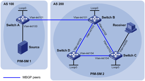
|
Device |
Interface |
IP address |
Device |
Interface |
IP address |
|
Source |
- |
10.110.1.100/24 |
Switch C |
Vlan-int200 |
10.110.2.1/24 |
|
Switch A |
Vlan-int100 |
10.110.1.1/24 |
|
Vlan-int102 |
192.168.2.2/24 |
|
|
Vlan-int101 |
192.168.1.1/24 |
|
Vlan-int104 |
192.168.4.1/24 |
|
|
Loop0 |
1.1.1.1/32 |
|
Loop0 |
3.3.3.3/32 |
|
Switch B |
Vlan-int101 |
192.168.1.2/24 |
Switch D |
Vlan-int103 |
192.168.3.2/24 |
|
|
Vlan-int102 |
192.168.2.1/24 |
|
Vlan-int104 |
192.168.4.2/24 |
|
|
Vlan-int103 |
192.168.3.1/24 |
|
Loop0 |
4.4.4.4/32 |
|
|
Loop0 |
2.2.2.2/32 |
|
|
|
Network requirements
l PIM-SM 1 is in AS 100 and PIM-SM 2 is in AS 200. OSPF is the IGP in the two ASs, and MBGP runs between the two ASs to exchange multicast route information.
l The multicast source belongs to PIM-SM 1, and the receiver belongs to PIM-SM 2.
l It is required that the respective Loopback 0 of Switch A and Switch B be configured as the C-BSR and C-RP of the respective PIM-SM domains.
l Switch A and Switch B establishes an MSDP peer relationship through MBGP.
Applicable product matrix
|
Product |
Software version |
Hardware version |
|
S7500E Series Ethernet Switches |
Release 6300 |
All versions |
Configuration procedure
1) Configure IP addresses for interfaces as shown in the above figure (omitted).
2) Configure OSPF (omitted).
3) Enable IP multicast routing, PIM-SM and IGMP, and configure a PIM-SM domain border.
# Enable IP multicast routing on Switch A, and enable PIM-SM on each interface.
<SwitchA> system-view
[SwitchA] multicast routing-enable
[SwitchA] interface vlan-interface 100
[SwitchA-Vlan-interface100] pim sm
[SwitchA-Vlan-interface100] quit
[SwitchA] interface vlan-interface 101
[SwitchA-Vlan-interface101] pim sm
[SwitchA-Vlan-interface101] quit
The configuration on Switch B and Switch D is similar to the configuration on Switch A.
# Enable IP multicast routing on Switch C, enable PIM-SM on each interface, and enable IGMP on the host-side interface VLAN-interface 200.
<SwitchC> system-view
[SwitchC] multicast routing-enable
[SwitchC] interface vlan-interface 102
[SwitchC-Vlan-interface102] pim sm
[SwitchC-Vlan-interface102] quit
[SwitchC] interface vlan-interface 104
[SwitchC-Vlan-interface104] pim sm
[SwitchC-Vlan-interface104] quit
[SwitchC] interface vlan-interface 200
[SwitchC-Vlan-interface200] pim sm
[SwitchC-Vlan-interface200] igmp enable
[SwitchC-Vlan-interface200] quit
# Configure a PIM domain border on Switch A.
[SwitchA] interface vlan-interface 101
[SwitchA-Vlan-interface101] pim bsr-boundary
[SwitchA-Vlan-interface101] quit
# Configure a PIM domain border on Switch B.
[SwitchB] interface vlan-interface 101
[SwitchB-Vlan-interface101] pim bsr-boundary
[SwitchB-Vlan-interface101] quit
4) Configure Loopback 0 and the position of C-BSR, and C-RP.
# Configure Loopback 0 and configure it as the C-BSR and C-RP on Switch A.
[SwitchA] interface loopback 0
[SwitchA-LoopBack0] ip address 1.1.1.1 32
[SwitchA-LoopBack0] pim sm
[SwitchA-LoopBack0] quit
[SwitchA] pim
[SwitchA-pim] c-bsr hash-length 32
[SwitchA-pim] c-bsr priority 20
[SwitchA-pim] c-bsr loopback 0
[SwitchA-pim] c-rp loopback 0
[SwitchA-pim] quit
# Configure Loopback 0 and configure it as the C-BSR and C-RP on Switch B.
[SwitchB] interface loopback 0
[SwitchB-LoopBack0] ip address 2.2.2.2 32
[SwitchB-LoopBack0] pim sm
[SwitchB-LoopBack0] quit
[SwitchB] pim
[SwitchB-pim] c-bsr hash-length 32
[SwitchB-pim] c-bsr priority 20
[SwitchB-pim] c-bsr loopback 0
[SwitchB-pim] c-rp loopback 0
[SwitchB-pim] quit
5) Configure BGP, specify the MBGP peer and enable direct route redistribution.
# On Switch A, configure the MBGP peer and enable direct route redistribution.
[SwitchA] bgp 100
[SwitchA-bgp] router-id 1.1.1.1
[SwitchA-bgp] peer 192.168.1.2 as-number 200
[SwitchA-bgp] import-route direct
[SwitchA-bgp] ipv4-family multicast
[SwitchA-bgp-af-mul] peer 192.168.1.2 enable
[SwitchA-bgp-af-mul] import-route direct
[SwitchA-bgp-af-mul] quit
[SwitchA-bgp] quit
# On Switch B, configure the MBGP peer and enable route redistribution from OSPF.
[SwitchB] bgp 200
[SwitchB-bgp] router-id 2.2.2.2
[SwitchB-bgp] peer 192.168.1.1 as-number 100
[SwitchB-bgp] import-route ospf 1
[SwitchB-bgp] ipv4-family multicast
[SwitchB-bgp-af-mul] peer 192.168.1.1 enable
[SwitchB-bgp-af-mul] import-route ospf 1
[SwitchB-bgp-af-mul] quit
[SwitchB-bgp] quit
6) Configure MSDP peer
# Specify the MSDP peer on Switch A.
[SwitchA] msdp
[SwitchA-msdp] peer 192.168.1.2 connect-interface vlan-interface 101
[SwitchA-msdp] quit
# Specify the MSDP peer on Switch B.
[SwitchB] msdp
[SwitchB-msdp] peer 192.168.1.1 connect-interface vlan-interface 101
[SwitchB-msdp] quit
7) Verify the configuration
You can use the display bgp multicast peer command to display MBGP peers on a switch. For example, display MBGP peers on Switch B.
[SwitchB] display bgp multicast peer
BGP local router ID : 2.2.2.2
Local AS number : 200
Total number of peers : 3 Peers in established state : 3
Peer V AS MsgRcvd MsgSent OutQ PrefRcv Up/Down State
192.168.1.1 4 100 56 56 0 0 00:40:54 Established
You can use the display msdp brief command to display MSDP peers on a switch. For example, display brief information about MSDP peers on Switch B.
[SwitchB] display msdp brief
MSDP Peer Brief Information of VPN-Instance: public net
Configured Up Listen Connect Shutdown Down
1 1 0 0 0 0
Peer's Address State Up/Down time AS SA Count Reset Count
192.168.1.1 Up 00:07:17 100 1 0
Complete configuration
l Configuration on SwitchA
#
multicast routing-enable
#
vlan 100 to 101
#
interface Vlan-interface100
pim sm
#
interface Vlan-interface101
pim bsr-boundary
pim sm
#
interface LoopBack0
ip address 1.1.1.1 255.255.255.255
pim sm
#
bgp 100
router-id 1.1.1.1
import-route direct
undo synchronization
peer 192.168.1.2 as-number 200
#
ipv4-family multicast
import-route direct
peer 192.168.1.2 enable
#
pim
c-bsr hash-length 32
c-bsr priority 20
c-bsr LoopBack0
c-rp LoopBack0
#
msdp
peer 192.168.1.2 connect-interface Vlan-interface101
l Configuration on SwitchB
#
multicast routing-enable
#
vlan 101 to 103
#
interface Vlan-interface101
pim bsr-boundary
pim sm
#
interface Vlan-interface102
pim sm
#
interface Vlan-interface103
pim sm
#
interface LoopBack0
ip address 2.2.2.2 255.255.255.255
pim sm
#
bgp 200
router-id 2.2.2.2
import-route ospf 1
undo synchronization
peer 192.168.1.1 as-number 100
#
ipv4-family multicast
import-route ospf 1
peer 192.168.1.1 enable
#
pim
c-bsr hash-length 32
c-bsr priority 20
c-bsr LoopBack0
c-rp LoopBack0
#
msdp
peer 192.168.1.1 connect-interface Vlan-interface101
l Configuration on SwitchC
#
multicast routing-enable
#
vlan 102
#
vlan 104
#
vlan200
#
interface Vlan-interface102
pim sm
#
interface Vlan-interface104
pim sm
#
interface Vlan-interface200
igmp enable
pim sm
l Configuration on SwitchD
#
multicast routing-enable
#
vlan 103 to 104
#
interface Vlan-interface103
pim sm
#
interface Vlan-interface104
pim sm
Configuration guidelines
l The Origin attribute of routes redistributed into the MBGP routing table with the import-route command is Incomplete.
l To configure an MBGP peer group, you need to enable the corresponding IPv4 BGP unicast peer group in IPv4 MBGP address family view.