- Table of Contents
-
- H3C Low-End and Mid-Range Ethernet Switches Configuration Examples(V1.01)
- 00-1Cover
- 01-Login Configuration Guide
- 02-VLAN Configuration Guide
- 03-GVRP Configuration Guide
- 04-Voice VLAN Configuration Guide
- 05-IP Addressing and Performance Configuration Guide
- 06-QinQ Configuration Guide
- 07-BPDU Tunnel Configuration Guide
- 08-VLAN Mapping Configuration Guide
- 09-MAC Address Table Management Configuration Guide
- 10-Link Aggregation Configuration Guide
- 11-IP Source Guard Configuration Guide
- 12-DLDP Configuration Guide
- 13-MSTP Configuration Guide
- 14-IPv4 Routing Configuration Guide
- 15-IPv6 Configuration Guide
- 16-IPv6 Routing Configuration Guide
- 17-IPv4 Multicast Configuration Guide
- 18-IPv6 Multicast Configuration Examples
- 19-802.1x Configuration Guide
- 20-AAA Configuration Guide
- 21-MAC Authentication Configuration Guide
- 22-Portal Configuration Guide
- 23-ARP Configuration Guide
- 24-DHCP Configuration Guide
- 25-ACL Configuration Guide
- 26-QoS Configuration Guide
- 27-Port Mirroring Configuration Guide
- 28-Cluster Management Configuration Guide
- 29-SNMP-RMON Configuration Guide
- 30-NTP Configuration Guide
- 31-FTP-TFTP Configuration Guide
- 32-UDP Helper Configuration Guide
- 33-Information Center Configuration Guide
- 34-DNS Configuration Guide
- 35-File System Management Configuration Guide
- 36-Remote Upgrade Configuration Guide
- 37-NQA Configuration Guide
- 38-VRRP Configuration Guide
- 39-SSH Configuration Guide
- 40-Port Security Configuration Guide
- 41-Port Isolation Configuration Guide
- 42-LLDP Configuration Guide
- 43-MCE Configuration Guide
- 44-PoE Configuration Guide
- 45-OAM Configuration Guide
- 46-Connectivity Fault Detection Configuration Guide
- 47-RRPP Configuration Guide
- 48-sFlow Configuration Guide
- 49-SSL-HTTPS Configuration Guide
- 50-PKI Configuration Guide
- 51-Track Configuration Guide
- 52-EPON-OLT Configuration Guide
- 53-Smart Link Configuration Guide
- 54-MPLS Configuration Guide
- Related Documents
-
| Title | Size | Download |
|---|---|---|
| 44-PoE Configuration Guide | 80.28 KB |
Table of Contents
Configuring PoE for Centralized Devices
Networking and Configuration Requirements
Configuring PoE for Distributed Devices
Networking and Configuration Requirements
PoE Overview
Power over Ethernet (PoE) means that power sourcing equipment (PSE) supplies power to powered devices (PD) such as IP telephone, wireless LAN access point, and web camera from Ethernet interfaces through twisted pair cables.
Configuring PoE for Centralized Devices
Network Diagram
Figure 1-1 Network diagram for PoE

Networking and Configuration Requirements
The switch supplies power to a PD through a PoE interface.
l GigabitEthernet 1/0/1 and GigabitEthernet 1/0/2 are connected to IP telephones.
l GigabitEthernet 1/0/11 and GigabitEthernet 1/0/12 are connected to access point (AP) devices.
l The power priority of GigabitEthernet 1/0/2 is critical. No power will be supplied to a new PD if the PSE power is overloaded, that is, the default policy of PD power management is adopted.
l The power of the AP device connected to GigabitEthernet 1/0/11 does not exceed 9,000 milliwatts.
Applicable Product Matrix
|
Product series |
Software version |
Hardware version |
|
S5500-SI Series Ethernet Switches |
Release 1207 |
PoE model of the S5500-SI series |
|
S5500-EI Series Ethernet Switches |
Release 2102 |
PoE model of the S5500-EI series |
Configuration Procedure
# Enable PoE on GigabitEthernet 1/0/1, GigabitEthernet 1/0/2, GigabitEthernet 1/0/11 and GigabitEthernet 1/0/12.
<Sysname> system-view
[Sysname] interface GigabitEthernet 1/0/1
[Sysname-GigabitEthernet1/0/1] poe enable
[Sysname-GigabitEthernet1/0/1] quit
[Sysname] interface GigabitEthernet 1/0/2
[Sysname-GigabitEthernet1/0/2] poe enable
[Sysname-GigabitEthernet1/0/2] quit
[Sysname] interface GigabitEthernet 1/0/11
[Sysname-GigabitEthernet1/0/11] poe enable
[Sysname-GigabitEthernet1/0/11] quit
[Sysname] interface GigabitEthernet 1/0/12
[Sysname-GigabitEthernet1/0/12] poe enable
[Sysname-GigabitEthernet1/0/12] return
# Set the power priority level of GigabitEthernet 1/0/2 to critical.
<Sysname> system-view
[Sysname] interface GigabitEthernet 1/0/2
[Sysname-GigabitEthernet1/0/2] poe priority critical
[Sysname-GigabitEthernet1/0/2] quit
# Set the maximum power of GigabitEthernet 1/0/11 to 9,000 milliwatts.
[Sysname] interface GigabitEthernet 1/0/11
[Sysname-GigabitEthernet1/0/11] poe max-power 9000
[Sysname-GigabitEthernet1/0/11] quit
After the above takes effect, the IP telephones and AP devices are powered and can work normally.
Complete Configuration
#
interface GigabitEthernet1/0/1
poe enable
#
interface GigabitEthernet1/0/2
poe enable
poe priority critical
#
interface GigabitEthernet1/0/11
poe enable
poe max-power 9000
#
interface GigabitEthernet1/0/12
poe enable
#
Configuration Guidelines
None
Configuring PoE for Distributed Devices
Network Diagram
Figure 1-2 Network diagram for PoE
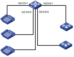
Networking and Configuration Requirements
The switch supplies power to a PD through a PoE interface.
l The device is equipped with two PoE-supporting cards, which are inserted in Slot 3 and Slot 5 respectively. The PSE IDs are 10 and 16.
l Allocate 400 watts to PSE 10, provided the default maximum power to PSE 16 can meet the requirements.
l GigabitEthernet 3/0/1 and GigabitEthernet 3/0/2 are connected to IP telephones.
l GigabitEthernet 5/0/1 and GigabitEthernet 5/0/2 are connected to access point (AP) devices.
l The power priority of GigabitEthernet 3/0/2 is critical. No power will be supplied to the new PD if the PSE power is overloaded, that is, the default policy of PD power management is adopted.
l The power of the AP device connected to GigabitEthernet 5/0/1 does not exceed 9,000 milliwatts.
Applicable Product Matrix
|
Product series |
Software version |
Hardware version |
|
S7500E Series Ethernet Switches |
Release 6100, Release 6300 |
The S7500E series(equipped with PoE-capable card) |
Configuration Procedure
# Enable PoE for the PSE.
<Sysname> system-view
[Sysname] poe enable pse 10
[Sysname] poe enable pse 16
# Set the maximum power of PSE to 400 watts.
[Sysname] poe max-power 400 pse 10
# Enable PoE on GigabitEthernet 3/0/1, GigabitEthernet 3/0/2, GigabitEthernet 5/0/1 and GigabitEthernet 5/0/2.
[Sysname] interface gigabitethernet 3/0/1
[Sysname-GigabitEthernet3/0/1] poe enable
[Sysname-GigabitEthernet3/0/1] quit
[Sysname] interface gigabitethernet 3/0/2
[Sysname-GigabitEthernet3/0/2] poe enable
[Sysname-GigabitEthernet3/0/2] quit
[Sysname] interface gigabitethernet 5/0/1
[Sysname-GigabitEthernet5/0/1] poe enable
[Sysname-GigabitEthernet5/0/1] quit
[Sysname] interface gigabitethernet 5/0/2
[Sysname-GigabitEthernet5/0/2] poe enable
[Sysname-GigabitEthernet5/0/2] quit
# Set the power priority level of GigabitEthernet 3/0/2 to critical.
[Sysname] interface gigabitethernet 3/0/2
[Sysname-GigabitEthernet3/0/2] poe priority critical
[Sysname-GigabitEthernet3/0/2] quit
# Set the maximum power of GigabitEthernet 5/0/1 to 9,000 milliwatts.
[Sysname] interface gigabitethernet 5/0/1
[Sysname-GigabitEthernet5/0/1] poe max-power 9000
After the above takes effect, the IP telephones and AP devices are powered and can work normally.
Complete Configuration
#
poe max-power 400 pse 10
poe enable pse 10
poe enable pse 16
#
interface GigabitEthernet3/0/1
poe enable
#
interface GigabitEthernet3/0/2
poe enable
poe priority critical
#
interface GigabitEthernet5/0/1
poe enable
poe max-power 9000
#
interface GigabitEthernet5/0/2
poe enable
Configuration Guidelines
To provide PoE supply to attached devices, the S7500E series require appropriate PoE power modules. PoE power modules fall into external and internal types.
1) The S7502E requires both internal power modules for its own power feed and an appropriate external PoE power module, PSE2500-A3 for example, to provide PoE supply.
2) The S7503E, S7506E, S7506E-V, and S7510E require only internal PoE power modules, PSR1400-D for example, for both their own power feed and PoE supply to attached devices.
For the details, refer to H3C S7500E Series Ethernet Switches Installation Manual.