- Table of Contents
-
- H3C Low-End and Mid-Range Ethernet Switches Configuration Examples(V1.01)
- 00-1Cover
- 01-Login Configuration Guide
- 02-VLAN Configuration Guide
- 03-GVRP Configuration Guide
- 04-Voice VLAN Configuration Guide
- 05-IP Addressing and Performance Configuration Guide
- 06-QinQ Configuration Guide
- 07-BPDU Tunnel Configuration Guide
- 08-VLAN Mapping Configuration Guide
- 09-MAC Address Table Management Configuration Guide
- 10-Link Aggregation Configuration Guide
- 11-IP Source Guard Configuration Guide
- 12-DLDP Configuration Guide
- 13-MSTP Configuration Guide
- 14-IPv4 Routing Configuration Guide
- 15-IPv6 Configuration Guide
- 16-IPv6 Routing Configuration Guide
- 17-IPv4 Multicast Configuration Guide
- 18-IPv6 Multicast Configuration Examples
- 19-802.1x Configuration Guide
- 20-AAA Configuration Guide
- 21-MAC Authentication Configuration Guide
- 22-Portal Configuration Guide
- 23-ARP Configuration Guide
- 24-DHCP Configuration Guide
- 25-ACL Configuration Guide
- 26-QoS Configuration Guide
- 27-Port Mirroring Configuration Guide
- 28-Cluster Management Configuration Guide
- 29-SNMP-RMON Configuration Guide
- 30-NTP Configuration Guide
- 31-FTP-TFTP Configuration Guide
- 32-UDP Helper Configuration Guide
- 33-Information Center Configuration Guide
- 34-DNS Configuration Guide
- 35-File System Management Configuration Guide
- 36-Remote Upgrade Configuration Guide
- 37-NQA Configuration Guide
- 38-VRRP Configuration Guide
- 39-SSH Configuration Guide
- 40-Port Security Configuration Guide
- 41-Port Isolation Configuration Guide
- 42-LLDP Configuration Guide
- 43-MCE Configuration Guide
- 44-PoE Configuration Guide
- 45-OAM Configuration Guide
- 46-Connectivity Fault Detection Configuration Guide
- 47-RRPP Configuration Guide
- 48-sFlow Configuration Guide
- 49-SSL-HTTPS Configuration Guide
- 50-PKI Configuration Guide
- 51-Track Configuration Guide
- 52-EPON-OLT Configuration Guide
- 53-Smart Link Configuration Guide
- 54-MPLS Configuration Guide
- Related Documents
-
| Title | Size | Download |
|---|---|---|
| 13-MSTP Configuration Guide | 105.03 KB |
Table of Contents
Networking and Configuration Requirements
Networking and Configuration Requirements
Configuring MSTP
Multiple Spanning Tree Protocol (MSTP) supports mapping multiple VLANs to one multiple spanning tree instance (MSTI) by means of a VLAN-to-MSTI mapping table. It allows data flows of VLANs to be forwarded along separate paths as defined in the mapping table, thus reducing communication overheads and resource usage. Note that one VLAN cannot map to multiple MSTIs.
Network Diagram
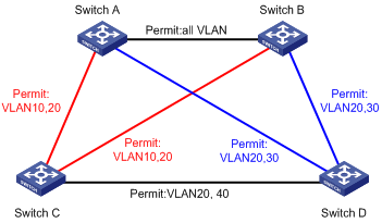
Figure 1-1 Network diagram for MSTP configuration
|
VLAN |
Map to MSTI |
|
VLAN 10 |
MSTI 1 |
|
VLAN 20 |
MSTI 0 |
|
VLAN 30 |
MSTI 3 |
|
VLAN 40 |
MSTI 4 |
![]()
"Permit:" beside each link in the figure is followed by the VLANs that the link carries.
Networking and Configuration Requirements
Configure MSTP so that packets of different VLANs are forwarded along different spanning trees. The configuration requirements are as follows:
l All switches on the network are in the same MST region.
l Packets of VLAN 10 are forwarded along MSTI 1, those of VLAN 30 are forwarded along MSTI 3, those of VLAN 40 are forwarded along MSTI 4, and those of VLAN 20 are forwarded along MSTI 0.
Switch A and Switch B are distribution layer devices, while Switch C and Switch D are access layer devices. Because VLAN 10 and VLAN 30 are terminated at the distribution layer, and VLAN 40 is terminated at the access layer, configure Switch A, Switch B, and Switch C as the root bridges of MSTI 1, MSTI 3, and MSTI 4 respectively.
Application Product Matrix
|
Product |
Software version |
Hardware version |
|
S3610 Series Ethernet Switches |
Release 5301, Release 5303 |
All versions |
|
S5510 Series Ethernet Switches |
Release 5301, Release 5303 |
All versions |
|
S5500-SI Series Ethernet Switches |
Release 1207 |
All versions except S5500-20TP-SI |
|
Release 1301 |
S5500-20TP-SI |
|
|
S5500-EI Series Ethernet Switches |
Release 2102 |
All versions |
|
S7500E Series Ethernet Switches |
Release 6100, Release 6300 |
All versions |
Configuration Procedure
1) Configure Switch A
# Enter MST region view.
<Sysname> system-view
[Sysname] stp region-configuration
# Configure the MST region name, VLAN-to-MSTI mapping, and revision level of the MST region.
[Sysname-mst-region] region-name example
[Sysname-mst-region] instance 1 vlan 10
[Sysname-mst-region] instance 3 vlan 30
[Sysname-mst-region] instance 4 vlan 40
[Sysname-mst-region] revision-level 0
# Activate the MST region configuration manually.
[Sysname-mst-region] active region-configuration
# Specify Switch A as the root bridge of MSTI 1.
[Sysname] stp instance 1 root primary
2) Configure Switch B
# Enter MST region view.
<Sysname> system-view
[Sysname] stp region-configuration
# Configure the MST region name, VLAN-to-MSTI mapping, and revision level of the MST region.
[Sysname-mst-region] region-name example
[Sysname-mst-region] instance 1 vlan 10
[Sysname-mst-region] instance 3 vlan 30
[Sysname-mst-region] instance 4 vlan 40
[Sysname-mst-region] revision-level 0
# Activate the MST region configuration manually.
[Sysname-mst-region] active region-configuration
# Specify Switch B as the root bridge of MSTI 3.
[Sysname] stp instance 3 root primary
3) Configure Switch C
# Enter MST region view. Configure the MST region name, VLAN-to-MSTI mapping and revision level of the MST region.
<Sysname> system-view
[Sysname] stp region-configuration
[Sysname-mst-region] region-name example
[Sysname-mst-region] instance 1 vlan 10
[Sysname-mst-region] instance 3 vlan 30
[Sysname-mst-region] instance 4 vlan 40
[Sysname-mst-region] revision-level 0
# Activate the MST region configuration manually.
[Sysname-mst-region] active region-configuration
# Specify Switch C as the root bridge of MSTI 4.
[Sysname] stp instance 4 root primary
4) Configure Switch D
# Enter MST region view.
<Sysname> system-view
[Sysname] stp region-configuration
# Configure the MST region name, VLAN-to-MSTI mapping, and revision level of the MST region.
[Sysname-mst-region] region-name example
[Sysname-mst-region] instance 1 vlan 10
[Sysname-mst-region] instance 3 vlan 30
[Sysname-mst-region] instance 4 vlan 40
[Sysname-mst-region] revision-level 0
# Activate the MST region configuration manually.
[Sysname-mst-region] active region-configuration
Complete Configuration
l Configuration on Switch A
#
stp instance 1 root primary
(stp enable)
stp region-configuration
region-name example
instance 1 vlan 10
instance 3 vlan 30
instance 4 vlan 40
active region-configuration
l Configuration on Switch B
#
stp instance 3 root primary
(stp enable)
stp region-configuration
region-name example
instance 1 vlan 10
instance 3 vlan 30
instance 4 vlan 40
active region-configuration
l Configuration on Switch C
#
stp instance 4 root primary
(stp enable)
stp region-configuration
region-name example
instance 1 vlan 10
instance 3 vlan 30
instance 4 vlan 40
active region-configuration
l Configuration on Switch D
#
(stp enable)
stp region-configuration
instance 1 vlan 10
instance 3 vlan 30
instance 4 vlan 40
active region-configuration
Configuration Guidelines
Follow these guidelines when configuring MSTP:
l MSTP is mutually exclusive with any of the following functions on a port: service loopback, RRPP, Smart Link, and STP BPDU tunnel.
l MSTP-enabled devices are considered in the same MST region only when they have the same format selector (protocol format selector defined in 802.1s, which is 0 by default and unconfigurable), region name, VLAN-to-MSTI mapping table, and MSTP revision level settings.
l For devices globally enabled with STP by default, the complete configuration does not display the stp enable command.
Configuring RSTP
The Rapid Spanning Tree Protocol (RSTP) is an optimized version of STP. RSTP allows a newly elected root port or designated port to enter the forwarding state much quicker under certain conditions than in STP, hence quicker network convergence.
Although RSTP allows quicker network convergence, it has the same drawback as STP does: All bridges within a LAN share the same spanning tree, so redundant links cannot be blocked based on VLAN and the packets of all VLANs are forwarded along the same spanning tree.
Network Diagram
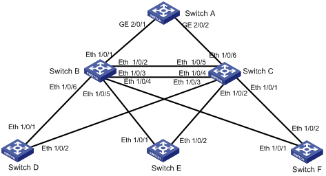
Figure 1-2 Network diagram for RSTP configuration
Networking and Configuration Requirements
1) Switch A at the core layer.
Configure it as the root bridge.
2) Switch B and Switch C at the distribution layer.
l Configure Switch C as the standby switch of Switch B. When Switch B fails, Switch C automatically takes over to forward data.
l Configure two links between Switch C and Switch B, ensuring one link is available when the other fails.
3) Switch D, Switch E, and Switch F at the access layer.
l User PCs are connected to Switch D, Switch E, and Switch F.
l Connect Switch D, Switch E, Switch F to Switch C and Switch B.
Only RSTP-related configurations are provided in the sample configuration. In addition, as the RSTP configurations on Switch D through Switch F are basically the same, only those on Switch D are provided.
![]()
l Switch A is a mid-range to high-end switch, such as an S7500E.
l Switch B and Switch C are typically the S3610 series or S5500 series of the low-end.
l Switch D, Switch E, Switch F are typically the S3100 series or S5100 series of the low-end.
Application Product Matrix
|
Product |
Software version |
Hardware version |
|
S3610 Series Ethernet Switches |
Release 5301, Release 5303 |
All versions |
|
S5510 Series Ethernet Switches |
Release 5301, Release 5303 |
All versions |
|
S5500-SI Series Ethernet Switches |
Release 1207 |
All versions except S5500-20TP-SI |
|
Release 1301 |
S5500-20TP-SI |
|
|
S5500-EI Series Ethernet Switches |
Release 2102 |
All versions |
|
S7500E Series Ethernet Switches |
Release 6100, Release 6300 |
All versions |
Configuration Procedure
1) Configure Switch A
# Enable RSTP.
<Sysname> system-view
[Sysname] stp enable
[Sysname] stp mode rstp
# RSTP is enabled globally by default on an MSTP-enabled device. Disable MSTP on the ports that do not take part in RSTP calculation. The following takes the configuration on GigabitEthernet 2/0/4 for example.
[Sysname] interface GigabitEthernet 2/0/4
[Sysname-GigabitEthernet2/0/4] stp disable
# Configure Switch A as the root bridge. Two ways are available:
l Set the bridge priority of Switch A to 0.
[Sysname] stp priority 0
l Specify Switch A as the root bridge with the stp root primary command.
[Sysname] stp root primary
# Enable root protection on the ports that connect to Switch B and Switch C.
[Sysname] interface GigabitEthernet 2/0/1
[Sysname-GigabitEthernet2/0/1] stp root-protection
[Sysname-GigabitEthernet2/0/1] quit
[Sysname] interface GigabitEthernet 2/0/2
[Sysname-GigabitEthernet2/0/2] stp root-protection
[Sysname-GigabitEthernet2/0/2] quit
# Enable TC-BPDU attack guard function for Switch A.
[Sysname] stp tc-protection enable
2) Configure Switch B
# Enable RSTP.
<Sysname> system-view
[Sysname] stp enable
[Sysname] stp mode rstp
# RSTP is enabled globally by default on MSTP-enabled devices. Disable MSTP for the ports that do not take part in RSTP calculation. The following takes the configuration on Ethernet 1/0/8 for example.
[Sysname] interface Ethernet 1/0/8
[Sysname-Ethernet1/0/8] stp disable
[Sysname-Ethernet1/0/8] quit
# Set the priority of Switch B to 4096.
[Sysname] stp priority 4096
# Enable root protection on the ports that connect to Switch D, Switch E, and Switch F.
[Sysname] interface Ethernet 1/0/4
[Sysname-Ethernet1/0/4] stp root-protection
[Sysname-Ethernet1/0/4] quit
[Sysname] interface Ethernet 1/0/5
[Sysname-Ethernet1/0/5] stp root-protection
[Sysname-Ethernet1/0/5] quit
[Sysname] interface Ethernet 1/0/6
[Sysname-Ethernet1/0/6] stp root-protection
[Sysname-Ethernet1/0/6] quit
# Use the default settings of MSTP work mode, time, and port parameters.
3) Configure Switch C
# Enable RSTP.
<Sysname> system-view
[Sysname] stp enable
[Sysname] stp mode rstp
# RSTP is enabled globally by default on MSTP-enabled devices. Disable MSTP on the ports that do not take part in RSTP calculation. The following takes the configuration on Ethernet 1/0/8 for example.
[Sysname] interface Ethernet 1/0/8
[Sysname-Ethernet1/0/8] stp disable
[Sysname-Ethernet1/0/8] quit
# Set the priority of Switch C to 8192. Switch C functions as the standby switch of Switch B.
[Sysname] stp priority 8192
# Enable root protection on the ports that connect to Switch D, Switch E, and Switch F.
[Sysname] interface Ethernet 1/0/1
[Sysname-Ethernet1/0/1] stp root-protection
[Sysname-Ethernet1/0/1] quit
[Sysname] interface Ethernet 1/0/2
[Sysname-Ethernet1/0/2] stp root-protection
[Sysname-Ethernet1/0/2] quit
[Sysname] interface Ethernet 1/0/3
[Sysname-Ethernet1/0/3] stp root-protection
[Sysname-Ethernet1/0/3] quit
# Use the default settings of MSTP operating mode, time, and port parameters.
4) Configure Switch D
# Enable RSTP.
<Sysname> system-view
[Sysname] stp enable
[Sysname] stp mode rstp
# RSTP is enabled globally by default on MSTP-enabled devices. Disable MSTP for the ports that do not take part in RSTP calculation. The following takes the configuration on Ethernet 1/0/3 for example.
[Sysname] interface Ethernet 1/0/3
[Sysname-Ethernet1/0/3] stp disable
# Configure the ports connecting to the terminals to edge ports and enable the BPDU protection function for Switch D. The following takes the configuration on Ethernet 1/0/3 for example.
[Sysname-Ethernet1/0/3] stp edged-port enable
[Sysname-Ethernet1/0/3] quit
[Sysname] stp bpdu-protection
# Use the default settings of MSTP operating mode, time, and port parameters.
# Perform the same configuration on Switch E and Switch F.
Complete Configuration
1) Configuration on Switch A
#
stp mode rstp
stp instance 0 priority 0
(stp instance 0 root primary)
stp TC-protection enable
stp enable
#
interface GigabitEthernet2/0/1
stp root-portection
#
interface GigabitEthernet2/0/2
stp root-portection
#
interface GigabitEthernet2/0/4
stp disable
2) Configuration on Switch B
#
stp mode rstp
stp instance 0 priority 4096
stp enable
#
interface Ethernet1/0/4
stp root-portection
#
interface Ethernet1/0/5
stp root-portection
#
interface Ethernet1/0/6
stp root-portection
#
interface Ethernet1/0/8
stp disable
3) Configuration on Switch C
#
stp mode rstp
stp instance 0 priority 8192
stp enable
#
interface Ethernet1/0/1
stp root-portection
#
interface Ethernet1/0/2
stp root-portection
#
interface Ethernet1/0/3
stp root-portection
#
interface Ethernet1/0/8
stp disable
4) Configuration on Switch D
#
stp mode rstp
stp enable
#
interface Ethernet1/0/3
stp disable
interface Ethernet3/0/5
stp edged-port enable
stp bpdu-portection
Configuration Guidelines
To change the STP mode between STP, RSPT, or MSTP, use the stp mode command. By default, an MSTP-enabled device works in MSTP mode.