- Table of Contents
-
- H3C Low-End and Mid-Range Ethernet Switches Configuration Examples(V1.01)
- 00-1Cover
- 01-Login Configuration Guide
- 02-VLAN Configuration Guide
- 03-GVRP Configuration Guide
- 04-Voice VLAN Configuration Guide
- 05-IP Addressing and Performance Configuration Guide
- 06-QinQ Configuration Guide
- 07-BPDU Tunnel Configuration Guide
- 08-VLAN Mapping Configuration Guide
- 09-MAC Address Table Management Configuration Guide
- 10-Link Aggregation Configuration Guide
- 11-IP Source Guard Configuration Guide
- 12-DLDP Configuration Guide
- 13-MSTP Configuration Guide
- 14-IPv4 Routing Configuration Guide
- 15-IPv6 Configuration Guide
- 16-IPv6 Routing Configuration Guide
- 17-IPv4 Multicast Configuration Guide
- 18-IPv6 Multicast Configuration Examples
- 19-802.1x Configuration Guide
- 20-AAA Configuration Guide
- 21-MAC Authentication Configuration Guide
- 22-Portal Configuration Guide
- 23-ARP Configuration Guide
- 24-DHCP Configuration Guide
- 25-ACL Configuration Guide
- 26-QoS Configuration Guide
- 27-Port Mirroring Configuration Guide
- 28-Cluster Management Configuration Guide
- 29-SNMP-RMON Configuration Guide
- 30-NTP Configuration Guide
- 31-FTP-TFTP Configuration Guide
- 32-UDP Helper Configuration Guide
- 33-Information Center Configuration Guide
- 34-DNS Configuration Guide
- 35-File System Management Configuration Guide
- 36-Remote Upgrade Configuration Guide
- 37-NQA Configuration Guide
- 38-VRRP Configuration Guide
- 39-SSH Configuration Guide
- 40-Port Security Configuration Guide
- 41-Port Isolation Configuration Guide
- 42-LLDP Configuration Guide
- 43-MCE Configuration Guide
- 44-PoE Configuration Guide
- 45-OAM Configuration Guide
- 46-Connectivity Fault Detection Configuration Guide
- 47-RRPP Configuration Guide
- 48-sFlow Configuration Guide
- 49-SSL-HTTPS Configuration Guide
- 50-PKI Configuration Guide
- 51-Track Configuration Guide
- 52-EPON-OLT Configuration Guide
- 53-Smart Link Configuration Guide
- 54-MPLS Configuration Guide
- Related Documents
-
| Title | Size | Download |
|---|---|---|
| 14-IPv4 Routing Configuration Guide | 993.52 KB |
Table of Contents
1 IPv4 Routing Configuration Guide
Networking and Configuration Requirements
Networking and Configuration Requirements
Configuring RIP Route Redistribution
Networking and Configuration Requirements
Configuring an Additional Metric for a RIP Interface
Networking and Configuration Requirements
Configuring RIP to Advertise a Summary Route
Networking and Configuration Requirements
Configuring OSPF Basic Functions
Networking and Configuration Requirements
Networking and Configuration Requirements
Configuring OSPF to Advertise a Summary Route
Networking and Configuration Requirements
Networking and Configuration Requirements
Networking and Configuration Requirements
Networking and Configuration Requirements
Configuring an OSPF Virtual Link
Networking and Configuration Requirements
Networking and Configuration Requirements
Networking and Configuration Requirements
Configuring IS-IS Basic Functions
Networking and Configuration Requirements
Configuring IS-IS DIS Election
Networking and Configuration Requirements
Configuring IS-IS Route Redistribution
Networking and Configuration Requirements
Networking and Configuration Requirements
Configuring IS-IS Authentication
Networking and Configuration Requirements
Configuring BGP Basic Functions
Networking and Configuration Requirements
Configuring BGP and IGP Route Synchronization
Networking and Configuration Requirements
Configuring BGP Load Balancing
Networking and Configuration Requirements
Networking and Configuration Requirements
Configuring BGP Route Reflector
Networking and Configuration Requirements
Networking and Configuration Requirements
Configuring BGP Path Selection
Networking and Configuration Requirements
Configuring Route Policy Application in IPv4 Route Redistribution
Networking and Configuration Requirements
Applying a Route Policy to Filter Received BGP Routes
Networking and Configuration Requirements
Configuring a Static Route
Static route
A static route is manually configured. If a network’s topology is simple, you only need to configure static routes for the network to work normally. The proper configuration and usage of static routes can improve network performance and ensure bandwidth for important network applications.
The disadvantage of using static routes is that they cannot adapt to network topology changes. If a fault or a topological change occurs in the network, some routes will be unreachable and the network breaks. In this case, the network administrator has to modify the static routes manually.
Default route
A router selects the default route only when it cannot find any matching entry in the routing table.
l If the destination address of a packet fails to match any entry in the routing table, the router selects the default route to forward the packet.
l If there is no default route and the destination address of the packet fails to match any entry in the routing table, the packet will be discarded and an ICMP packet will be sent to the source to report that the destination or the network is unreachable.
Default routes can be configured in two ways:
l The network administrator can configure a default route with both destination and mask being 0.0.0.0.
l Some dynamic routing protocols, such as OSPF, RIP and IS-IS, can also generate default routes.
1.1.1 Network Diagram
Figure 1-1 Network diagram for static route configuration
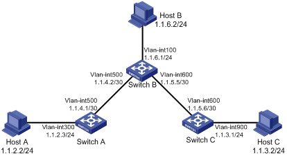
Networking and Configuration Requirements
The IP addresses and masks of the switches and hosts are shown in the following figure. Static routes are required for interconnection between any two hosts.
Applicable Product Matrix
|
Product series |
Software version |
Hardware version |
|
S3610 Series Ethernet Switches |
Release 5301, Release 5303 |
All versions |
|
S5510 Series Ethernet Switches |
Release 5301, Release 5303 |
All versions |
|
S5500-SI Series Ethernet Switches |
Release 1207 |
All versions (except S5500-20TP-SI) |
|
Release 1301 |
S5500-20TP-SI |
|
|
S5500-EI Series Ethernet Switches |
Release 2102 |
All versions |
|
S7500E Series Ethernet Switches |
Release 6100, Release 6300 |
All versions |
Configuration Procedure
1) Configuring IP addresses for interfaces (omitted)
2) Configuring static routes
# Configure a default route on Switch A.
<SwitchA> system-view
[SwitchA] ip route-static 0.0.0.0 0.0.0.0 1.1.4.2
# Configure two static routes on Switch B.
<SwitchB> system-view
[SwitchB] ip route-static 1.1.2.0 255.255.255.0 1.1.4.1
[SwitchB] ip route-static 1.1.3.0 255.255.255.0 1.1.5.6
# Configure a default route on Switch C
<SwitchC> system-view
[SwitchC] ip route-static 0.0.0.0 0.0.0.0 1.1.5.5
3) Configure the hosts.
The default gateways for the three hosts A, B and C are 1.1.2.3, 1.1.6.1 and 1.1.3.1 respectively. The configuration procedure is omitted.
Complete Configuration
l Configure Switch A
#
vlan 300
#
vlan 500
#
interface Vlan-interface300
ip address 1.1.2.3 255.255.255.0
#
interface Vlan-interface500
ip address 1.1.4.1 255.255.255.252
#
ip route-static 0.0.0.0 0.0.0.0 1.1.4.2
#
l Configure Switch B
#
vlan 100
#
vlan 500
#
vlan 600
#
interface Vlan-interface100
ip address 1.1.6.1 255.255.255.0
#
interface Vlan-interface500
ip address 1.1.4.2 255.255.255.252
#
interface Vlan-interface600
ip address 1.1.5.5 255.255.255.252
#
ip route-static 1.1.2.0 255.255.255.0 1.1.4.1
ip route-static 1.1.3.0 255.255.255.0 1.1.5.6
#
l Configure Switch C
#
vlan 600
#
vlan 900
#
interface Vlan-interface600
ip address 1.1.5.6 255.255.255.252
#
interface Vlan-interface900
ip address 1.1.3.1 255.255.255.0
#
ip route-static 0.0.0.0 0.0.0.0 1.1.5.5
#
Configuration Guidelines
l You are not recommended to specify a broadcast interface (such as VLAN interface) as the output interface, because a broadcast interface may have multiple next hops. If you have to do so, you must specify the corresponding next hop for the output interface.
l You can configure different preferences for different static routes so that route management policies can be applied more flexibly. For example, specifying the same preference for different routes to the same destination enables load sharing, while specifying different preferences for these routes enables route backup.
l When you configure a static route, the static route does not take effect if you specify the next hop address first and then configure it as the IP address of a local interface, such as VLAN interface.
Configuring the RIP Version
RIP is a simple Interior Gateway Protocol (IGP), mainly used in small-sized networks, such as academic networks and simple LANs. RIP is not applicable to complex networks.
RIP is still widely used in practical networking due to easier implementation, configuration and maintenance than OSPF and IS-IS.
Network Diagram
Figure 1-2 Network diagram for RIP route redistribution configuration
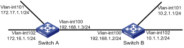
Networking and Configuration Requirements
As shown inFigure 1-2, enable RIPv2 on all interfaces on Switch A and Switch B.
Applicable Product Matrix
|
Product series |
Software version |
Hardware version |
|
S3610 Series Ethernet Switches |
Release 5301, Release 5303 |
All versions |
|
S5510 Series Ethernet Switches |
Release 5301, Release 5303 |
All versions |
|
S5500-SI Series Ethernet Switches |
Release 1207 |
All versions, except S5500-20TP-SI |
|
Release 1301 |
S5500-20TP-SI |
|
|
S5500-EI Series Ethernet Switches |
Release 2102 |
All versions |
|
S7500E Series Ethernet Switches |
Release 6100, Release 6300 |
All versions |
Configuration Procedure
1) Configure an IP addresses for interfaces (omitted).
2) Configure RIP basic functions.
# Configure Switch A.
<SwitchA> system-view
[SwitchA] rip
[SwitchA-rip-1] network 192.168.1.0
[SwitchA-rip-1] network 172.16.0.0
[SwitchA-rip-1] network 172.17.0.0
[SwitchA-rip-1] quit
# Configure Switch B.
<SwitchB> system-view
[SwitchB] rip
[SwitchB-rip-1] network 192.168.1.0
[SwitchB-rip-1] network 10.0.0.0
[SwitchB-rip-1] quit
# Display the RIP routing table of Switch A.
[SwitchA] display rip 1 route
Route Flags: R - RIP, T - TRIP
P - Permanent, A - Aging, S - Suppressed, G - Garbage-collect
--------------------------------------------------------------------------
Peer 192.168.1.2 on Vlan-interface100
Destination/Mask Nexthop Cost Tag Flags Sec
10.0.0.0/8 192.168.1.2 1 0 RA 11
From the routing table, you can find that RIPv1 uses a natural mask.
3) Configure RIP version
# Configure RIPv2 on Switch A.
[SwitchA] rip
[SwitchA-rip-1] version 2
[SwitchA-rip-1] undo summary
# Configure RIPv2 on Switch B.
[SwitchB] rip
[SwitchB-rip-1] version 2
[SwitchB-rip-1] undo summary
# Display the RIP routing table on Switch A.
[SwitchA] display rip 1 route
Route Flags: R - RIP, T - TRIP
P - Permanent, A - Aging, S - Suppressed, G - Garbage-collect
--------------------------------------------------------------------------
Peer 192.168.1.2 on Vlan-interface100
Destination/Mask Nexthop Cost Tag Flags Sec
10.2.1.0/24 192.168.1.2 1 0 RA 16
10.1.1.0/24 192.168.1.2 1 0 RA 16
From the routing table, you can see RIPv2 uses a classless subnet mask.
![]()
Since RIPv1 routing information has a long aging time, it may still exist until it ages out after RIPv2 is configured.
Complete Configuration
l Configure Switch A.
#
vlan 100 to 102
#
interface Vlan-interface100
ip address 192.168.1.3 255.255.255.0
#
interface Vlan-interface101
ip address 172.17.1.1 255.255.255.0
#
interface Vlan-interface102
ip address 172.16.1.1 255.255.255.0
#
rip 1
undo summary
version 2
network 192.168.1.0
network 172.16.0.0
network 172.17.0.0
#
l Configure Switch B.
#
vlan 100 to 102
#
interface Vlan-interface100
ip address 192.168.1.2 255.255.255.0
#
interface Vlan-interface101
ip address 10.2.1.1 255.255.255.0
#
interface Vlan-interface102
ip address 10.1.1.2 255.255.255.0
#
rip 1
undo summary
version 2
network 192.168.1.0
network 10.0.0.0
#
Configuration Guidelines
l The S5500-EI series switches with the software version Release 2102 support only RIP single process.
l The S5500-SI series switches with the software versions Release 1207 or Release 1301 support only RIP single process.
l RIPv2 has two types of message transmission: broadcast and multicast. Multicast is the default type using 224.0.0.9 as the multicast address. The interface working in the RIPv2 broadcast mode can also receive RIPv1 messages.
l RIP runs only on the interfaces residing on the specified networks. Therefore, you need to specify the network after enabling RIP to validate RIP on a specific interface.
Configuring RIP Route Redistribution
Network Diagram
Figure 1-3 Network diagram for RIP interface additional metric configuration
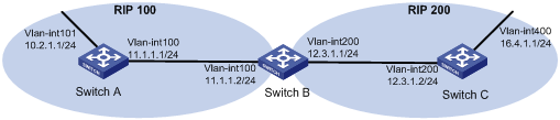
Networking and Configuration Requirements
l Two RIP processes are running on Switch B, which communicates with Switch A through RIP 100 and with Switch C through RIP 200.
l Configure route redistribution on Switch B to make RIP 200 redistribute direct routes and routes from RIP 100. Thus, Switch C can learn routes destined for 10.2.1.0/24 and 11.1.1.0/24, while Switch A cannot learn routes destined for 12.3.1.0/24 and 16.4.1.0/24.
l Configure a filtering policy on Switch B to filter out the route 10.2.1.1/24 from RIP 100, making the route not advertised to Switch C.
Applicable Product Matrix
|
Product series |
Software version |
Hardware version |
|
S3610 Series Ethernet Switches |
Release 5301, Release 5303 |
All versions |
|
S5510 Series Ethernet Switches |
Release 5301, Release 5303 |
All versions |
|
S7500E Series Ethernet Switches |
Release 6100, Release 6300 |
All versions |
Configuration Procedure
1) Configure IP addresses for interfaces (omitted).
2) Configure RIP basic functions.
# Enable RIP 100 and specify RIP version 2 on Switch A.
<SwitchA> system-view
[SwitchA] rip 100
[SwitchA-rip-100] network 10.0.0.0
[SwitchA-rip-100] network 11.0.0.0
[SwitchA-rip-100] version 2
[SwitchA-rip-100] undo summary
[SwitchA-rip-100] quit
# Enable RIP 100 and RIP 200 and specify RIP version 2 on Switch B.
<SwitchB> system-view
[SwitchB] rip 100
[SwitchB-rip-100] network 11.0.0.0
[SwitchB-rip-100] version 2
[SwitchB-rip-100] undo summary
[SwitchB-rip-100] quit
[SwitchB] rip 200
[SwitchB-rip-200] network 12.0.0.0
[SwitchB-rip-200] version 2
[SwitchB-rip-200] undo summary
[SwitchB-rip-200] quit
# Enable RIP 200 and specify RIP version 2 on Switch C.
<SwitchC> system-view
[SwitchC] rip 200
[SwitchC-rip-200] network 13.0.0.0
[SwitchC-rip-200] network 16.0.0.0
[SwitchC-rip-200] version 2
[SwitchC-rip-200] undo summary
# Display the routing table of Switch C.
[SwitchC] display ip routing-table
Routing Tables: Public
Destinations : 6 Routes : 6
Destination/Mask Proto Pre Cost NextHop Interface
12.3.1.0/24 Direct 0 0 12.3.1.2 Vlan200
12.3.1.2/32 Direct 0 0 127.0.0.1 InLoop0
16.4.1.0/24 Direct 0 0 16.4.1.1 Vlan400
16.4.1.1/32 Direct 0 0 127.0.0.1 InLoop0
127.0.0.0/8 Direct 0 0 127.0.0.1 InLoop0
127.0.0.1/32 Direct 0 0 127.0.0.1 InLoop0
3) Configure route redistribution
# On Switch B, configure RIP 200 to redistribute direct routes and routes from RIP 100.
[SwitchB] rip 200
[SwitchB-rip-200] import-route rip 100
[SwitchB-rip-200] import-route direct
[SwitchB-rip-200] quit
# Display the routing table of Switch C.
[SwitchC] display ip routing-table
Routing Tables: Public
Destinations : 8 Routes : 8
Destination/Mask Proto Pre Cost NextHop Interface
10.2.1.0/24 RIP 100 1 12.3.1.1 Vlan200
11.1.1.0/24 RIP 100 1 12.3.1.1 Vlan200
12.3.1.0/24 Direct 0 0 12.3.1.2 Vlan200
12.3.1.2/32 Direct 0 0 127.0.0.1 InLoop0
16.4.1.0/24 Direct 0 0 16.4.1.1 Vlan400
16.4.1.1/32 Direct 0 0 127.0.0.1 InLoop0
127.0.0.0/8 Direct 0 0 127.0.0.1 InLoop0
127.0.0.1/32 Direct 0 0 127.0.0.1 InLoop0
4) Configure a filtering policy to filter redistributed routes.
# Define ACL 2000 and reference it to a filtering policy to filter routes redistributed from RIP 100 on Switch B, making the route not advertised to Switch C.
[SwitchB] acl number 2000
[SwitchB-acl-basic-2000] rule deny source 10.2.1.1 0.0.0.255
[SwitchB-acl-basic-2000] rule permit
[SwitchB-acl-basic-2000] quit
[SwitchB] rip 200
[SwitchB-rip-100] filter-policy 2000 export rip 100
# Display the routing table of Switch C.
[SwitchC] display ip routing-table
Routing Tables: Public
Destinations : 7 Routes : 7
Destination/Mask Proto Pre Cost NextHop Interface
11.1.1.0/24 RIP 100 1 12.3.1.1 Vlan200
12.3.1.0/24 Direct 0 0 12.3.1.2 Vlan200
12.3.1.2/32 Direct 0 0 127.0.0.1 InLoop0
16.4.1.0/24 Direct 0 0 16.4.1.1 Vlan400
16.4.1.1/32 Direct 0 0 127.0.0.1 InLoop0
127.0.0.0/8 Direct 0 0 127.0.0.1 InLoop0
127.0.0.1/32 Direct 0 0 127.0.0.1 InLoop0
Complete Configuration
l Configure Switch A
#
vlan 100 to 101
#
interface Vlan-interface100
ip address 11.1.1.1 255.255.255.0
#
interface Vlan-interface101
ip address 10.2.1.1 255.255.255.0
#
rip 100
undo summary
version 2
network 10.0.0.0
network 11.0.0.0
#
l Configure Switch B
#
acl number 2000
rule 0 deny source 10.2.1.0 0.0.0.255
rule 5 permit
#
vlan 100
#
vlan 200
#
interface Vlan-interface100
ip address 11.1.1.2 255.255.255.0
#
interface Vlan-interface200
ip address 12.3.1.1 255.255.255.0
#
rip 100
undo summary
version 2
network 11.0.0.0
#
rip 200
undo summary
version 2
network 12.0.0.0
filter-policy 2000 export rip 100
import-route direct
import-route rip 100
#
l Configure Switch C
#
vlan 200
#
vlan 400
#
interface Vlan-interface200
ip address 12.3.1.2 255.255.255.0
#
interface Vlan-interface400
ip address 16.4.1.1 255.255.255.0
#
rip 200
undo summary
version 2
network 13.0.0.0
network 16.0.0.0
#
Configuration Guidelines
None
Configuring an Additional Metric for a RIP Interface
Network Diagram
Networking and Configuration Requirements
l RIP is enabled on all the interfaces of Switch A, Switch B, Switch C, Switch D, and Switch E. The switches are interconnected through RIPv2.
l Switch A has two links to Switch D. The link from Switch B to Switch D is more stable than that from Switch C to Switch D. Configure an additional metric for RIP routes received through VLAN-interface 200 on Switch A so that Switch A prefers the 1.1.5.0/24 network learned from Switch B.
Applicable Product Matrix
|
Product series |
Software version |
Hardware version |
|
S3610 Series Ethernet Switches |
Release 5301, Release 5303 |
All versions |
|
S5510 Series Ethernet Switches |
Release 5301, Release 5303 |
All versions |
|
S5500-EI Series Ethernet Switches |
Release 2102 |
All versions |
|
S7500E Series Ethernet Switches |
Release 6100, Release 6300 |
All versions |
Configuration Procedure
1) Configure IP addresses for the interfaces (omitted).
2) Configure RIP basic functions.
# Configure Switch A.
<SwitchA> system-view
[SwitchA] rip 1
[SwitchA-rip-1] network 1.0.0.0
[SwitchA-rip-1] version 2
[SwitchA-rip-1] undo summary
[SwitchA-rip-1] quit
# Configure Switch B.
<SwitchB> system-view
[SwitchB] rip 1
[SwitchB-rip-1] network 1.0.0.0
[SwitchB-rip-1] version 2
[SwitchB-rip-1] undo summary
# Configure Switch C.
<SwitchC> system-view
[SwitchB] rip 1
[SwitchC-rip-1] network 1.0.0.0
[SwitchC-rip-1] version 2
[SwitchC-rip-1] undo summary
# Configure Switch D.
<SwitchD> system-view
[SwitchD] rip 1
[SwitchD-rip-1] network 1.0.0.0
[SwitchD-rip-1] version 2
[SwitchD-rip-1] undo summary
# Configure Switch E.
<SwitchE> system-view
[SwitchE] rip 1
[SwitchE-rip-1] network 1.0.0.0
[SwitchE-rip-1] version 2
[SwitchE-rip-1] undo summary
# Display the IP routing table of Switch A.
[SwitchA] display rip 1 database
1.0.0.0/8, cost 0, ClassfulSumm
1.1.1.0/24, cost 0, nexthop 1.1.1.1, Rip-interface
1.1.2.0/24, cost 0, nexthop 1.1.2.1, Rip-interface
1.1.3.0/24, cost 1, nexthop 1.1.1.2
1.1.4.0/24, cost 1, nexthop 1.1.2.2
1.1.5.0/24, cost 2, nexthop 1.1.1.2
1.1.5.0/24, cost 2, nexthop 1.1.2.2
The display shows that there are two RIP routes to network 1.1.5.0/24. Their nexthops are Switch B (1.1.1.2) and Switch C (1.1.2.2) respectively, with the same cost of 2. Switch C is the nexthop router to reach network 1.1.4.0/24, with a cost of 1.
3) Configure an additional metric for the RIP interface.
# Configure an additional metric of 3 for VLAN-interface 200 on Switch A.
[SwitchA] interface vlan-interface 200
[SwitchA-Vlan-interface200] rip metricin 3
[SwitchA-Vlan-interface200] display rip 1 database
1.0.0.0/8, cost 0, ClassfulSumm
1.1.1.0/24, cost 0, nexthop 1.1.1.1, Rip-interface
1.1.2.0/24, cost 0, nexthop 1.1.2.1, Rip-interface
1.1.3.0/24, cost 1, nexthop 1.1.1.2
1.1.4.0/24, cost 2, nexthop 1.1.1.2
1.1.5.0/24, cost 2, nexthop 1.1.1.2
The display shows that there is only one RIP route to network 1.1.5.0/24, with the nexthop as Switch B (1.1.1.2) and a cost of 2.
Complete Configuration
l Configure Switch A.
#
vlan 100
#
vlan 200
#
interface Vlan-interface100
ip address 1.1.1.1 255.255.255.0
#
interface Vlan-interface200
ip address 1.1.2.1 255.255.255.0
rip metricin 3
#
rip 1
undo summary
version 2
network 1.0.0.0
#
l Configure Switch B.
#
vlan 100
#
vlan 400
#
interface Vlan-interface100
ip address 1.1.1.2 255.255.255.0
#
interface Vlan-interface400
ip address 1.1.3.1 255.255.255.0
#
rip 1
undo summary
version 2
network 1.0.0.0
#
l Configure Switch C.
#
vlan 200
#
vlan 300
#
interface Vlan-interface200
ip address 1.1.2.2 255.255.255.0
#
interface Vlan-interface300
ip address 1.1.4.1 255.255.255.0
#
rip 1
undo summary
version 2
network 1.0.0.0
#
l Configure Switch D.
#
vlan 300
#
vlan 400
#
vlan 500
#
interface Vlan-interface300
ip address 1.1.4.2 255.255.255.0
#
interface Vlan-interface400
ip address 1.1.3.2 255.255.255.0
#
interface Vlan-interface500
ip address 1.1.5.1 255.255.255.0
#
rip 1
undo summary
version 2
network 1.0.0.0
#
l Configure Switch E.
#
vlan 500
#
interface Vlan-interface500
ip address 1.1.5.2 255.255.255.0
#
rip 1
undo summary
version 2
network 1.0.0.0
#
Configuration Guidelines
None
Configuring RIP to Advertise a Summary Route
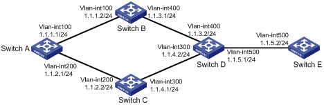
Network Diagram
Figure 1-4 Network diagram for RIP summary route advertisement
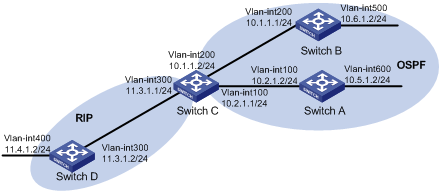
Networking and Configuration Requirements
l Switch A and Switch B run OSPF, Switch D runs RIP, and Switch C runs OSPF and RIP.
l Configure RIP to redistribute OSPF routes on Switch C so that Switch D has routes destined for networks 10.1.1.0/24, 10.2.1.0/24, 10.5.1.0/24, and 10.6.1.0/24.
l Route summarization is configured on Switch C and only the summary route 10.0.0.0/8 is advertised, thus reducing the routing table size of Switch D.
Applicable Product Matrix
|
Product series |
Software version |
Hardware version |
|
S3610 Series Ethernet Switches |
Release 5301 Release 5303 |
All versions |
|
S5510 Series Ethernet Switches |
Release 5301 Release 5303 |
All versions |
|
S5500-EI Series Ethernet Switches |
Release 2102 |
All versions |
|
S7500E Series Ethernet Switches |
Release 6100 Release 6300 |
All versions |
Configuration Procedure
1) Configure IP addresses for interfaces (omitted)
2) Configure OSPF basic functions
# Configure Switch A.
<SwitchA> system-view
[SwitchA] ospf
[SwitchA-ospf-1] area 0
[SwitchA-ospf-1-area-0.0.0.0] network 10.5.1.0 0.0.0.255
[SwitchA-ospf-1-area-0.0.0.0] network 10.2.1.0 0.0.0.255
[SwitchA-ospf-1-area-0.0.0.0] quit
# Configure Switch B.
<SwitchB> system-view
[SwitchB] ospf
[SwitchB-ospf-1] area 0
[SwitchB-ospf-1-area-0.0.0.0] network 10.1.1.0 0.0.0.255
[SwitchB-ospf-1-area-0.0.0.0] network 10.6.1.0 0.0.0.255
[SwitchB-ospf-1-area-0.0.0.0] quit
# Configure Switch C.
<SwitchC> system-view
[SwitchC] ospf
[SwitchC-ospf-1] area 0
[SwitchC-ospf-1-area-0.0.0.0] network 10.1.1.0 0.0.0.255
[SwitchC-ospf-1-area-0.0.0.0] network 10.2.1.0 0.0.0.255
[SwitchC-ospf-1-area-0.0.0.0] quit
3) Configure RIP basic functions.
# Configure Switch C.
<SwitchC> system-view
[SwitchC] rip 1
[SwitchC-rip-1] network 11.3.1.0
[SwitchC-rip-1] version 2
[SwitchC-rip-1] undo summary
# Configure Switch D.
<SwitchD> system-view
[SwitchD] rip 1
[SwitchD-rip-1] network 11.0.0.0
[SwitchD-rip-1] version 2
[SwitchD-rip-1] undo summary
[SwitchD-rip-1] quit
# Configure RIP to redistribute the routes from OSPF process 1 and direct routes on Switch C.
[SwitchC-rip-1] import-route direct
[SwitchC-rip-1] import-route ospf 1
# Display the routing table information of Switch D.
[SwitchD] display ip routing-table
Routing Tables: Public
Destinations : 10 Routes : 10
Destination/Mask Proto Pre Cost NextHop Interface
10.1.1.0/24 RIP 100 1 11.3.1.1 Vlan300
10.2.1.0/24 RIP 100 1 11.3.1.1 Vlan300
10.5.1.0/24 RIP 100 1 11.3.1.1 Vlan300
10.6.1.0/24 RIP 100 1 11.3.1.1 Vlan300
11.3.1.0/24 Direct 0 0 11.3.1.2 Vlan300
11.3.1.2/32 Direct 0 0 127.0.0.1 InLoop0
11.4.1.0/24 Direct 0 0 11.4.1.2 Vlan400
11.4.1.2/32 Direct 0 0 127.0.0.1 InLoop0
127.0.0.0/8 Direct 0 0 127.0.0.1 InLoop0
127.0.0.1/32 Direct 0 0 127.0.0.1 InLoop0
4) Configure route summarization on Switch C and advertise only the summary route 10.0.0.0/8.
[SwitchC] interface vlan-interface 300
[SwitchC-Vlan-interface300] rip summary-address 10.0.0.0 8
# Display the routing table information of Switch D.
[SwitchD] display ip routing-table
Routing Tables: Public
Destinations : 7 Routes : 7
Destination/Mask Proto Pre Cost NextHop Interface
10.0.0.0/8 RIP 100 1 11.3.1.1 Vlan300
11.3.1.0/24 Direct 0 0 11.3.1.2 Vlan300
11.3.1.2/32 Direct 0 0 127.0.0.1 InLoop0
11.4.1.0/24 Direct 0 0 11.4.1.2 Vlan400
11.4.1.2/32 Direct 0 0 127.0.0.1 InLoop0
127.0.0.0/8 Direct 0 0 127.0.0.1 InLoop0
127.0.0.1/32 Direct 0 0 127.0.0.1 InLoop0
Complete Configuration
l Configure Switch A
#
vlan 100
#
vlan 600
#
interface Vlan-interface100
ip address 10.2.1.2 255.255.255.0
#
interface Vlan-interface600
ip address 10.5.1.2 255.255.255.0
#
ospf 1
area 0.0.0.0
network 10.5.1.0 0.0.0.255
network 10.2.1.0 0.0.0.255
#
l Configure Switch B
#
vlan 200
#
vlan 500
#
interface Vlan-interface200
ip address 10.1.1.1 255.255.255.0
#
interface Vlan-interface500
ip address 10.6.1.2 255.255.255.0
#
ospf 1
area 0.0.0.0
network 10.1.1.0 0.0.0.255
network 10.6.1.0 0.0.0.255
#
l Configure Switch C
#
vlan 100
#
vlan 200
#
vlan 300
#
interface Vlan-interface100
ip address 10.2.1.1 255.255.255.0
#
interface Vlan-interface200
ip address 10.1.1.2 255.255.255.0
#
interface Vlan-interface300
ip address 11.3.1.1 255.255.255.0
rip summary-address 10.0.0.0 255.0.0.0
#
ospf 1
area 0.0.0.0
network 10.1.1.0 0.0.0.255
network 10.2.1.0 0.0.0.255
#
rip 1
undo summary
version 2
network 11.0.0.0
import-route direct
import-route ospf 1
#
l Configure Switch D
#
vlan 300
#
vlan 400
#
interface Vlan-interface300
ip address 11.3.1.2 255.255.255.0
#
interface Vlan-interface400
ip address 11.4.1.2 255.255.255.0
#
rip 1
undo summary
version 2
network 11.0.0.0
#
Configuration Guidelines
None
Configuring OSPF Basic Functions
Open Shortest Path First (OSPF) is a link state interior gateway protocol developed by the OSPF working group of the Internet Engineering Task Force (IETF). At present, OSPF version 2 (RFC2328) is used.
OSPF has the following features:
l Wide scope: Supports networks of various sizes and up to several hundred routers in an OSPF routing domain.
l Fast convergence: Transmits updates instantly after network topology changes for routing information synchronization in the AS.
l Loop-free: Computes routes with the shortest path first (SPF) algorithm according to collected link states, so no route loops are generated.
l Area partition: Allows an AS to be split into different areas for ease of management and routing information transmitted between areas is summarized to reduce network bandwidth consumption.
l Equal-cost routes: Supports multiple equal-cost routes to a destination.
l Routing hierarchy: Supports a four-level routing hierarchy that prioritizes routes into intra-area, inter-area, external Type-1, and external Type-2 routes.
l Authentication: Supports interface-based packet authentication to ensure the security of packet exchange.
l Multicast: Supports multicasting protocol packets on some types of links.
Network Diagram
Figure 1-5 Network diagram for typical OSPF application configuration
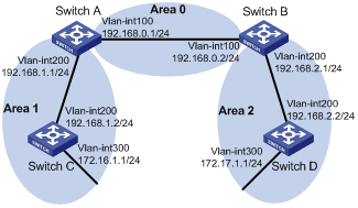
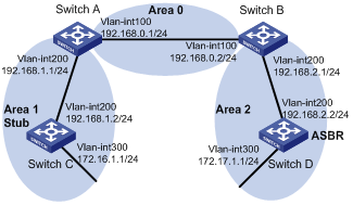
Networking and Configuration Requirements
l As shown in the figure above, all switches run OSPF. The AS is split into three areas, in which Switch A and Switch B act as ABRs to forward routing information between areas.
l After configuration, all switches can learn routes to every network segment in the AS.
Applicable Product Matrix
|
Product series |
Software version |
Hardware version |
|
S3610 Series Ethernet Switches |
Release 5301 Release 5303 |
All versions |
|
S5510 Series Ethernet Switches |
Release 5301 Release 5303 |
All versions |
|
S5500-EI Series Ethernet Switches |
Release 2102 |
All versions |
|
S7500E Series Ethernet Switches |
Release 6100 Release 6300 |
All versions |
Configuration Procedure
1) Configure IP addresses for interfaces (omitted)
2) Configure OSPF basic functions
# Configure Switch A.
<SwitchA> system-view
[SwitchA] ospf
[SwitchA-ospf-1] area 0
[SwitchA-ospf-1-area-0.0.0.0] network 192.168.0.0 0.0.0.255
[SwitchA-ospf-1-area-0.0.0.0] quit
[SwitchA-ospf-1] area 1
[SwitchA-ospf-1-area-0.0.0.1] network 192.168.1.0 0.0.0.255
[SwitchA-ospf-1-area-0.0.0.1] quit
[SwitchA-ospf-1] quit
# Configure Switch B.
<SwitchB> system-view
[SwitchB] ospf
[SwitchB-ospf-1] area 0
[SwitchB-ospf-1-area-0.0.0.0] network 192.168.0.0 0.0.0.255
[SwitchB-ospf-1-area-0.0.0.0] quit
[SwitchB-ospf-1] area 2
[SwitchB-ospf-1-area-0.0.0.2] network 192.168.2.0 0.0.0.255
[SwitchB-ospf-1-area-0.0.0.2] quit
[SwitchB-ospf-1] quit
# Configure Switch C
<SwitchC> system-view
[SwitchC] ospf
[SwitchC-ospf-1] area 1
[SwitchC-ospf-1-area-0.0.0.1] network 192.168.1.0 0.0.0.255
[SwitchC-ospf-1-area-0.0.0.1] network 172.16.1.0 0.0.0.255
[SwitchC-ospf-1-area-0.0.0.1] quit
[SwitchC-ospf-1] quit
# Configure Switch D
<SwitchD> system-view
[SwitchD] ospf
[SwitchD-ospf-1] area 2
[SwitchD-ospf-1-area-0.0.0.2] network 192.168.2.0 0.0.0.255
[SwitchD-ospf-1-area-0.0.0.2] network 172.17.1.0 0.0.0.255
[SwitchD-ospf-1-area-0.0.0.2] quit
[SwitchD-ospf-1] quit
3) Verify the configuration
# Display information about neighbors on Switch A
[SwitchA] display ospf peer verbose
OSPF Process 1 with Router ID 192.168.0.1
Neighbors
Area 0.0.0.0 interface 192.168.0.1(Vlan-interface 100)'s neighbors
Router ID: 192.168.0.2 Address: 192.168.0.2 GR State: Normal
State: Full Mode:Nbr is Master Priority: 1
DR: 192.168.0.2 BDR: 192.168.0.1 MTU: 0
Dead timer due in 36 sec
Neighbor is up for 00:15:04
Authentication Sequence: [ 0 ]
Neighbor state change count: 3
Neighbors
Area 0.0.0.1 interface 192.168.1.1(Vlan-interface 200)'s neighbors
Router ID: 192.168.1.2 Address: 192.168.1.2 GR State: Normal
State: Full Mode:Nbr is Slave Priority: 1
DR: 192.168.1.2 BDR: 192.168.1.1 MTU: 0
Dead timer due in 39 sec
Neighbor is up for 00:07:32
Authentication Sequence: [ 0 ]
Neighbor state change count: 2
# Display OSPF routing information on Switch A.
[SwitchA] display ospf routing
OSPF Process 1 with Router ID 192.168.0.1
Routing Tables
Routing for Network
Destination Cost Type NextHop AdvRouter Area
172.16.1.0/24 1563 Stub 192.168.1.2 172.16.1.1 0.0.0.1
172.17.1.0/24 3125 Inter-area 192.168.0.2 192.168.2.1 0.0.0.0
192.168.1.0/24 1562 Stub 192.168.1.1 192.168.0.1 0.0.0.1
192.168.2.0/24 3124 Inter-area 192.168.0.2 192.168.2.1 0.0.0.0
192.168.0.0/24 1562 Stub 192.168.0.1 192.168.0.1 0.0.0.0
Total Nets: 5
Intra Area: 3 Inter Area: 2 ASE: 0 NSSA: 0
# # Display the Link State Database on Switch A.
[SwitchA] display ospf lsdb
OSPF Process 1 with Router ID 192.168.0.1
Link State Data Base
Area: 0.0.0.0
Type LinkState ID AdvRouter Age Len Sequence Metric
Router 192.168.2.1 192.168.2.1 874 48 80000006 1562
Router 192.168.0.1 192.168.0.1 976 48 80000005 1562
Sum-Net 192.168.1.0 192.168.0.1 630 28 80000001 1562
Sum-Net 172.17.1.0 192.168.2.1 411 28 80000001 1563
Sum-Net 192.168.2.0 192.168.2.1 429 28 80000001 1562
Sum-Net 172.16.1.0 192.168.0.1 565 28 80000001 1563
Area: 0.0.0.1
Type LinkState ID AdvRouter Age Len Sequence Metric
Router 192.168.1.2 192.168.1.2 964 48 80000003 1562
Router 192.168.0.1 192.168.0.1 590 48 80000002 1562
Router 172.16.1.1 172.16.1.1 526 60 80000005 1562
Sum-Net 172.17.1.0 192.168.0.1 410 28 80000001 3125
Sum-Net 192.168.2.0 192.168.0.1 428 28 80000001 3124
Sum-Net 192.168.0.0 192.168.0.1 630 28 80000001 1562
# Display OSPF routing information on Switch D.
[SwitchD] display ospf routing
OSPF Process 1 with Router ID 192.168.2.2
Routing Tables
Routing for Network
Destination Cost Type NextHop AdvRouter Area
172.16.1.0/24 4687 Inter-area 192.168.2.1 192.168.2.1 0.0.0.2
172.17.1.0/24 1 Stub 172.17.1.1 192.168.2.2 0.0.0.2
192.168.1.0/24 4686 Inter-area 192.168.2.1 192.168.2.1 0.0.0.2
192.168.2.0/24 1562 Stub 192.168.2.2 192.168.2.2 0.0.0.2
192.168.0.0/24 3124 Inter-area 192.168.2.1 192.168.2.1 0.0.0.2
Total Nets: 5
Intra Area: 2 Inter Area: 3 ASE: 0 NSSA: 0
# On Switch D, ping the IP address 172.16.1.1 to check connectivity.
[SwitchD] ping 172.16.1.1
PING 172.16.1.1: 56 data bytes, press CTRL_C to break
Reply from 172.16.1.1: bytes=56 Sequence=1 ttl=253 time=62 ms
Reply from 172.16.1.1: bytes=56 Sequence=2 ttl=253 time=16 ms
Reply from 172.16.1.1: bytes=56 Sequence=3 ttl=253 time=62 ms
Reply from 172.16.1.1: bytes=56 Sequence=4 ttl=253 time=94 ms
Reply from 172.16.1.1: bytes=56 Sequence=5 ttl=253 time=63 ms
--- 172.16.1.1 ping statistics ---
5 packet(s) transmitted
5 packet(s) received
0.00% packet loss
round-trip min/avg/max = 16/59/94 ms
Complete Configuration
l Configure Switch A
#
vlan 100
#
vlan 200
#
interface Vlan-interface100
ip address 192.168.0.1 255.255.255.0
#
interface Vlan-interface200
ip address 192.168.1.1 255.255.255.0
#
ospf 1
area 0.0.0.0
network 192.168.0.0 0.0.0.255
area 0.0.0.1
network 192.168.1.0 0.0.0.255
#
l Configure Switch B
#
vlan 100
#
vlan 200
#
interface Vlan-interface100
ip address 192.168.0.2 255.255.255.0
#
interface Vlan-interface200
ip address 192.168.2.1 255.255.255.0
#
ospf 1
area 0.0.0.0
network 192.168.0.0 0.0.0.255
area 0.0.0.2
network 192.168.2.0 0.0.0.255
#
l Configure Switch C
#
vlan 200
#
vlan 300
#
interface Vlan-interface200
ip address 192.168.1.2 255.255.255.0
#
interface Vlan-interface300
ip address 172.16.1.1 255.255.255.0
#
ospf 1
area 0.0.0.1
network 192.168.1.0 0.0.0.255
network 172.16.1.0 0.0.0.255
#
l Configure Switch D
#
vlan 200
#
vlan 300
#
interface Vlan-interface200
ip address 192.168.2.2 255.255.255.0
#
interface Vlan-interface300
ip address 172.17.1.1 255.255.255.0
#
ospf 1
area 0.0.0.2
network 192.168.2.0 0.0.0.255
network 172.17.1.0 0.0.0.255
#
Configuration Guidelines
l The S5500-EI series switches with the software version Release 2102 support only OSPF single process.
l You need to enable OSPF, specify an interface and area ID first before performing other tasks.
l A network segment can only belong to one area.
Configuring OSPF
Network Diagram
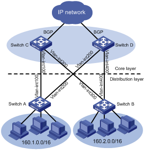
Figure 1-6 Network diagram for OSPF summary route advertisement
|
Device |
Interface |
IP address |
Device |
Interface |
IP address |
|
Switch A |
Vlan-int100 |
10.1.1.1/24 |
Switch C |
Vlan-int100 |
10.1.1.2/24 |
|
|
Vlan-int200 |
10.1.2.1/24 |
|
Vlan-int300 |
10.1.3.2/24 |
|
Switch B |
Vlan-int300 |
10.1.3.1/24 |
Switch D |
Vlan-int200 |
10.1.2.2/24 |
|
|
Vlan-int400 |
10.1.4.1/24 |
|
Vlan-int400 |
10.1.4.2/24 |
Networking and Configuration Requirements
An enterprise has two branches, and each branch network is connected to the external network through the backbone network of the enterprise. The backbone network consists of four core switches, two of which connect to the branch networks as distribution layer devices. Each of these two switches provides two uplinks (for redundant backup) connected to two core switches for access to the external network. It is required to meet the following requirements:
l The distribution layer switches and core layer switches are interconnected at Layer-3. They belong to area 0 with OSPF enabled.
l On the distribution layer devices, advertise the branch networks (160.1.0.0/16 and 160.2.0.0/16) into OSPF so that the two core-layer devices can learn the routes to the branch networks.
l The core-layer switches learn routes through BGP and redistribute the learned BGP routes into OSPF so that ultimately the two distribution-layer switches each have two equal-cost routes to the external network.
Applicable Product Matrix
|
Product series |
Software version |
Hardware version |
|
S3610 Series Ethernet Switches |
Release 5301 Release 5303 |
All versions |
|
S5510 Series Ethernet Switches |
Release 5301 Release 5303 |
All versions |
|
S5500-EI Series Ethernet Switches |
Release 2102 |
All versions |
|
S7500E Series Ethernet Switches |
Release 6100 Release 6300 |
All versions |
Configuration Procedure
The following example gives only OSPF-related configuration. For the configuration of BGP route learning and redistribution, see the related sections in BGP configuration examples.
1) Configure IP addresses for the interfaces (omitted)
2) Configure OSPF
# Configure Switch A.
<SwitchA> system-view
[SwitchA] ospf
[SwitchA-ospf-1] area 0
[SwitchA-ospf-1-area-0.0.0.0] network 10.1.1.0 0.0.0.255
[SwitchA-ospf-1-area-0.0.0.0] network 10.1.2.0 0.0.0.255
[SwitchA-ospf-1-area-0.0.0.0] quit
[SwitchA-ospf-1] quit
# Configure Switch B.
<SwitchB> system-view
[SwitchB] ospf
[SwitchB-ospf-1] area 0
[SwitchB-ospf-1-area-0.0.0.0] network 10.1.3.0 0.0.0.255
[SwitchB-ospf-1-area-0.0.0.0] network 10.1.4.0 0.0.0.255
[SwitchB-ospf-1-area-0.0.0.0] quit
# Configure Switch C.
<SwitchC> system-view
[SwitchC] ospf
[SwitchC-ospf-1] area 0
[SwitchC-ospf-1-area-0.0.0.0] network 10.1.1.0 0.0.0.255
[SwitchC-ospf-1-area-0.0.0.0] network 10.1.3.0 0.0.0.255
[SwitchC-ospf-1-area-0.0.0.0] quit
[SwitchC-ospf-1] quit
# Configure Switch D.
<SwitchD> system-view
[SwitchD] ospf
[SwitchD-ospf-1] area 0
[SwitchD-ospf-1-area-0.0.0.0] network 10.1.2.0 0.0.0.255
[SwitchD-ospf-1-area-0.0.0.0] network 10.1.4.0 0.0.0.255
[SwitchD-ospf-1-area-0.0.0.0] quit
[SwitchC-ospf-1] quit
# Display the routing table of Switch A (assume three branch networks are attached to Switch A).
[SwitchA] display ip routing-table
Routing Tables: Public
Destinations : 14 Routes : 14
Destination/Mask Proto Pre Cost NextHop Interface
10.1.1.0/24 Direct 0 0 10.1.1.1 Vlan100
10.1.1.1/32 Direct 0 0 127.0.0.1 InLoop0
10.1.2.0/24 Direct 0 0 10.1.2.1 Vlan200
10.1.2.1/32 Direct 0 0 127.0.0.1 InLoop0
10.1.3.0/24 OSPF 10 2 10.1.1.2 Vlan100
10.1.4.0/24 OSPF 10 2 10.1.2.2 Vlan200
127.0.0.0/8 Direct 0 0 127.0.0.1 InLoop0
127.0.0.1/32 Direct 0 0 127.0.0.1 InLoop0
160.1.1.0/24 Direct 0 0 160.1.1.1 Vlan1
160.1.1.1/32 Direct 0 0 127.0.0.1 InLoop0
160.1.2.0/24 Direct 0 0 160.1.2.1 Vlan2
160.1.2.1/32 Direct 0 0 127.0.0.1 InLoop0
160.1.3.0/24 Direct 0 0 160.1.3.1 Vlan3
160.1.3.1/32 Direct 0 0 127.0.0.1 InLoop0
3) Configure route redistribution.
# On Switch A, configure OSPF to redistribute direct routes and advertise only the summary route 160.1.0.0/16.
[SwitchA] ospf
[SwitchA-ospf-1] import-route direct
[SwitchA-ospf-1] asbr-summary 160.1.0.0 16
# On Switch B, configure OSPF to redistribute direct routes and advertise only the summary route 160.2.0.0/16.
[SwitchB] ospf
[SwitchB-ospf-1] import-route direct
[SwitchB-ospf-1] asbr-summary 160.2.0.0 16
# Configure OSPF to redistribute routes from BGP on Switch C.
[SwitchC] ospf
[SwitchC-ospf-1] import-route bgp
# Configure OSPF to redistribute routes from BGP on Switch D.
[SwitchD] ospf
[SwitchD-ospf-1] import-route bgp
Complete Configuration
l Configure Switch A.
#
vlan 100
#
vlan 200
#
interface Vlan-interface100
ip address 10.1.1.1 255.255.255.0
#
interface Vlan-interface200
ip address 10.1.2.1 255.255.255.0
#
ospf 1
asbr-summary 160.1.0.0 255.255.0.0
import-route direct
area 0.0.0.0
network 10.1.1.0 0.0.0.255
network 10.1.2.0 0.0.0.255
#
l Configure Switch B.
#
vlan 300
#
vlan 400
#
interface Vlan-interface300
ip address 10.1.3.1 255.255.255.0
#
interface Vlan-interface400
ip address 10.1.4.1 255.255.255.0
#
ospf 1
asbr-summary 160.2.0.0 255.255.0.0
import-route direct
area 0.0.0.0
network 10.1.3.0 0.0.0.255
network 10.1.4.0 0.0.0.255
#
l Configure Switch C.
#
vlan 100
#
vlan 300
#
interface Vlan-interface100
ip address 10.1.1.2 255.255.255.0
#
interface Vlan-interface300
ip address 10.1.3.2 255.255.255.0
#
ospf 1
import-route bgp
area 0.0.0.0
network 10.1.1.0 0.0.0.255
network 10.1.3.0 0.0.0.255
#
l Configure Switch D.
#
vlan 200
#
vlan 400
#
interface Vlan-interface200
ip address 10.1.2.2 255.255.255.0
#
interface Vlan-interface400
ip address 10.1.4.2 255.255.255.0
#
ospf 1
import-route bgp
area 0.0.0.0
network 10.1.2.0 0.0.0.255
network 10.1.4.0 0.0.0.255
#
Configuration Guidelines
None
Configuring OSPF to Advertise a Summary Route
Network Diagram
Figure 1-7 OSPF Stub area configuration
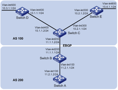
Networking and Configuration Requirements
l Switch A and Switch B are in AS 200, which runs OSPF.
l Switch C, Switch D, and Switch E are in AS 100, which runs OSPF.
l An eBGP connection is established between Switch B and Switch C. Switch C is configured to redistribute OSPF routes into BGP.
l Switch B is configured to redistribute BGP routes into OSPF. Switch B is configured with route summarization and advertises only the summary route 10.0.0.0/8 to reduce Switch A's routing table size.
Applicable Product Matrix
|
Product series |
Software version |
Hardware version |
|
S3610 Series Ethernet Switches |
Release 5301 Release 5303 |
All versions |
|
S5510 Series Ethernet Switches |
Release 5301 Release 5303 |
All versions |
|
S5500-EI Series Ethernet Switches |
Release 2102 |
All versions |
|
S7500E Series Ethernet Switches |
Release 6100 Release 6300 |
All versions |
Configuration Procedure
1) Configure IP addresses for interfaces (omitted)
2) Configure OSPF basic functions
# Configure Switch A.
<SwitchA> system-view
[SwitchA] ospf
[SwitchA-ospf-1] area 0
[SwitchA-ospf-1-area-0.0.0.0] network 11.2.1.0 0.0.0.255
[SwitchA-ospf-1-area-0.0.0.0] quit
[SwitchA-ospf-1] quit
# Configure Switch B.
<SwitchB> system-view
[SwitchB] ospf
[SwitchB-ospf-1] area 0
[SwitchB-ospf-1-area-0.0.0.0] network 11.2.1.0 0.0.0.255
[SwitchB-ospf-1-area-0.0.0.0] quit
# Configure Switch C.
<SwitchC> system-view
[SwitchC] ospf
[SwitchC-ospf-1] area 0
[SwitchC-ospf-1-area-0.0.0.0] network 10.1.1.0 0.0.0.255
[SwitchC-ospf-1-area-0.0.0.0] network 10.2.1.0 0.0.0.255
[SwitchC-ospf-1-area-0.0.0.0] quit
[SwitchC-ospf-1] quit
# Configure Switch D.
<SwitchD> system-view
[SwitchD] ospf
[SwitchD-ospf-1] area 0
[SwitchD-ospf-1-area-0.0.0.0] network 10.1.1.0 0.0.0.255
[SwitchD-ospf-1-area-0.0.0.0] network 10.3.1.0 0.0.0.255
[SwitchD-ospf-1-area-0.0.0.0] quit
# Configure Switch E.
<SwitchE> system-view
[SwitchE] ospf
[SwitchE-ospf-1] area 0
[SwitchE-ospf-1-area-0.0.0.0] network 10.2.1.0 0.0.0.255
[SwitchE-ospf-1-area-0.0.0.0] network 10.4.1.0 0.0.0.255
[SwitchE-ospf-1-area-0.0.0.0] quit
[SwitchE-ospf-1] quit
3) Configure BGP
# Configure Switch B.
<SwitchB> system-view
[SwitchB] bgp 200
[SwitchB-bgp] peer 11.1.1.2 as-number 100
[SwitchB-bgp] quit
# Configure Switch C.
<SwitchC> system-view
[SwitchC] bgp 100
[SwitchC-bgp] peer 11.1.1.1 as-number 200
[SwitchC-bgp] import-route ospf
4) Configure route redistribution on Switch B.
# Configure OSPF to redistribute routes from BGP on Switch B.
[SwitchB] ospf
[SwitchB-ospf-1] import-route bgp
# Display the OSPF routing table of Switch A.
[SwitchA] display ip routing-table
Routing Tables: Public
Destinations : 8 Routes : 8
Destination/Mask Proto Pre Cost NextHop Interface
10.1.1.0/24 O_ASE 150 1 11.2.1.1 Vlan100
10.2.1.0/24 O_ASE 150 1 11.2.1.1 Vlan100
10.3.1.0/24 O_ASE 150 1 11.2.1.1 Vlan100
10.4.1.0/24 O_ASE 150 1 11.2.1.1 Vlan100
11.2.1.0/24 Direct 0 0 11.2.1.2 Vlan100
11.2.1.2/32 Direct 0 0 127.0.0.1 InLoop0
127.0.0.0/8 Direct 0 0 127.0.0.1 InLoop0
127.0.0.1/32 Direct 0 0 127.0.0.1 InLoop0
5) # Configure summary route 10.0.0.0/8 on Switch B and advertise it.
[SwitchB-ospf-1] asbr-summary 10.0.0.0 8
# Display the OSPF routing table of Switch A.
[SwitchA] display ip routing-table
Routing Tables: Public
Destinations : 5 Routes : 5
Destination/Mask Proto Pre Cost NextHop Interface
10.0.0.0/8 O_ASE 150 2 11.2.1.1 Vlan100
11.2.1.0/24 Direct 0 0 11.2.1.2 Vlan100
11.2.1.2/32 Direct 0 0 127.0.0.1 InLoop0
127.0.0.0/8 Direct 0 0 127.0.0.1 InLoop0
127.0.0.1/32 Direct 0 0 127.0.0.1 InLoop0
Complete Configuration
l Configure Switch A
#
vlan 100
#
interface Vlan-interface100
ip address 11.2.1.2 255.255.255.0
#
ospf 1
area 0.0.0.0
network 11.2.1.0 0.0.0.255
#
l Configure Switch B
#
vlan 100
#
vlan 200
#
interface Vlan-interface100
ip address 11.2.1.1 255.255.255.0
#
interface Vlan-interface200
ip address 11.1.1.1 255.255.255.0
#
bgp 200
undo synchronization
peer 11.1.1.2 as-number 100
#
ospf 1
asbr-summary 10.0.0.0 255.0.0.0
import-route bgp
area 0.0.0.0
network 11.2.1.0 0.0.0.255
#
l Configure Switch C
#
vlan 200
#
vlan 300
#
vlan 400
#
interface Vlan-interface200
ip address 11.1.1.2 255.255.255.0
#
interface Vlan-interface300
ip address 10.2.1.1 255.255.255.0
#
interface Vlan-interface400
ip address 10.1.1.2 255.255.255.0
#
bgp 100
import-route ospf 1
undo synchronization
peer 11.1.1.1 as-number 200
#
ospf 1
area 0.0.0.0
network 10.1.1.0 0.0.0.255
network 10.2.1.0 0.0.0.255
#
l Configure Switch D
#
vlan 400
#
vlan 500
#
interface Vlan-interface400
ip address 10.1.1.1 255.255.255.0
#
interface Vlan-interface500
ip address 10.3.1.1 255.255.255.0
#
ospf 1
area 0.0.0.0
network 10.1.1.0 0.0.0.255
network 10.3.1.0 0.0.0.255
#
l Configure Switch E
#
vlan 300
#
vlan 600
#
interface Vlan-interface300
ip address 10.2.1.2 255.255.255.0
#
interface Vlan-interface600
ip address 10.4.1.1 255.255.255.0
#
ospf 1
area 0.0.0.0
network 10.2.1.0 0.0.0.255
network 10.4.1.0 0.0.0.255
#
Configuration Guidelines
None
Configuring an OSPF Stub Area
Splitting an OSPF AS into multiple areas reduces the number of LSAs in the networks and extends the OSPF application. For those non-backbone areas residing on the AS boundary, you can configure them as stub areas to further reduce the size of routing tables on routers in these areas and the number of LSAs.
Network Diagram
Figure 1-8 Network diagram for OSPF NSSA area configuration
Networking and Configuration Requirements
The following figure shows an AS is split into three areas, where all switches run OSPF. Switch A and Switch B act as ABRs to forward routing information between areas. Switch D acts as the ASBR and is enabled to redistribute static routes.
It is required to configure Area 1 as a Stub area, reducing LSAs to this area without influencing route reachability.
Applicable Product Matrix
|
Product series |
Software version |
Hardware version |
|
S3610 Series Ethernet Switches |
Release 5301 Release 5303 |
All versions |
|
S5510 Series Ethernet Switches |
Release 5301 Release 5303 |
All versions |
|
S5500-EI Series Ethernet Switches |
Release 2102 |
All versions |
|
S7500E Series Ethernet Switches |
Release 6100 Release 6300 |
All versions |
Configuration Procedure
1) Configure IP addresses for interfaces (omitted)
2) Configure OSPF basic functions (refer to Configuring OSPF Basic Functions.)
3) Configure Switch D to redistribute static routes
[SwitchD] ip route-static 200.0.0.0 8 null 0
[SwitchD] ospf
[SwitchD-ospf-1] import-route static
[SwitchD-ospf-1] quit
# Display the ABR/ASBR information of Switch C.
[SwitchC] display ospf abr-asbr
OSPF Process 1 with Router ID 172.16.1.1
Routing Table to ABR and ASBR
Type Destination Area Cost Nexthop RtType
Intra-area 192.168.0.1 0.0.0.1 1562 192.168.1.1 ABR
Inter-area 172.17.1.1 0.0.0.1 4686 192.168.1.1 ASBR
# Display OSPF routing information on Switch C.
[SwitchC] display ospf routing
OSPF Process 1 with Router ID 172.16.1.1
Routing Tables
Routing for Network
Destination Cost Type NextHop AdvRouter Area
172.16.1.0/24 1 Stub 172.16.1.1 172.16.1.1 0.0.0.1
172.17.1.0/24 4687 Inter-area 192.168.1.1 192.168.0.1 0.0.0.1
192.168.1.0/24 1562 Stub 192.168.1.2 172.16.1.1 0.0.0.1
192.168.2.0/24 4686 Inter-area 192.168.1.1 192.168.0.1 0.0.0.1
192.168.0.0/24 3124 Inter-area 192.168.1.1 192.168.0.1 0.0.0.1
Routing for ASEs
Destination Cost Type Tag NextHop AdvRouter
200.0.0.0/8 10 Type2 1 192.168.1.1 172.17.1.1
Routing for NSSAs
Destination Cost Type Tag NextHop AdvRouter
Total Nets: 6
Intra Area: 2 Inter Area: 3 ASE: 1 NSSA: 0
![]()
In the above output, since Switch C resides in a normal OSPF area, its routing table contains an external route.
4) Configure Area1 as a Stub area
# Configure Switch A.
[SwitchA] ospf
[SwitchA-ospf-1] area 1
[SwitchA-ospf-1-area-0.0.0.1] stub
[SwitchA-ospf-1-area-0.0.0.1] quit
[SwitchA-ospf-1] quit
# Configure Switch C.
[SwitchC] ospf
[SwitchC-ospf-1] stub-router
[SwitchC-ospf-1] area 1
[SwitchC-ospf-1-area-0.0.0.1] stub
[SwitchC-ospf-1-area-0.0.0.1] quit
[SwitchC-ospf-1] quit
# Display OSPF routing information on Switch C
[SwitchC] display ospf routing
OSPF Process 1 with Router ID 172.16.1.1
Routing Tables
Routing for Network
Destination Cost Type NextHop AdvRouter Area
0.0.0.0/0 65536 Inter-area 192.168.1.1 192.168.0.1 0.0.0.1
172.16.1.0/24 1 Stub 172.16.1.1 172.16.1.1 0.0.0.1
172.17.1.0/24 68660 Inter-area 192.168.1.1 192.168.0.1 0.0.0.1
192.168.1.0/24 1562 Stub 192.168.1.2 172.16.1.1 0.0.0.1
192.168.2.0/24 68659 Inter-area 192.168.1.1 192.168.0.1 0.0.0.1
192.168.0.0/24 67097 Inter-area 192.168.1.1 192.168.0.1 0.0.0.1
Total Nets: 6
Intra Area: 2 Inter Area: 4 ASE: 0 NSSA: 0
![]()
When Switch C resides in the Stub area, a default route takes the place of the external route.
# Filter Type-3 LSAs out the stub area
[SwitchA] ospf
[SwitchA-ospf-1] area 1
[SwitchA-ospf-1-area-0.0.0.1] stub no-summary
[SwitchA-ospf-1-area-0.0.0.1] quit
# Display OSPF routing information on Switch C.
[SwitchC] display ospf routing
OSPF Process 1 with Router ID 172.16.1.1
Routing Tables
Routing for Network
Destination Cost Type NextHop AdvRouter Area
0.0.0.0/0 1563 Inter-area 192.168.1.1 192.168.0.1 0.0.0.1
172.16.1.0/24 1 Stub 172.16.1.1 172.16.1.1 0.0.0.1
192.168.1.0/24 1562 Stub 192.168.1.2 172.16.1.1 0.0.0.1
Total Nets: 3
Intra Area: 2 Inter Area: 1 ASE: 0 NSSA: 0
![]()
After this configuration, routing entries on the stub router are further reduced, containing only one default external route.
Complete Configuration
l Configure Switch A
#
vlan 100
#
vlan 200
#
interface Vlan-interface100
ip address 192.168.0.1 255.255.255.0
#
interface Vlan-interface200
ip address 192.168.1.1 255.255.255.0
#
ospf 1
area 0.0.0.0
network 192.168.0.0 0.0.0.255
area 0.0.0.1
network 192.168.1.0 0.0.0.255
stub no-summary
#
l Configure Switch B
#
vlan 100
#
vlan 200
#
interface Vlan-interface100
ip address 192.168.0.2 255.255.255.0
#
interface Vlan-interface200
ip address 192.168.2.1 255.255.255.0
#
ospf 1
area 0.0.0.0
network 192.168.0.0 0.0.0.255
area 0.0.0.2
network 192.168.2.0 0.0.0.255
#
l Configure Switch C
#
vlan 200
#
vlan 300
#
interface Vlan-interface200
ip address 192.168.1.2 255.255.255.0
#
interface Vlan-interface300
ip address 172.16.1.1 255.255.255.0
#
ospf 1
stub-router
area 0.0.0.1
network 192.168.1.0 0.0.0.255
network 172.16.1.0 0.0.0.255
stub
#
l Configure Switch D
#
vlan 200
#
vlan 300
#
interface Vlan-interface200
ip address 192.168.2.2 255.255.255.0
#
interface Vlan-interface300
ip address 172.17.1.1 255.255.255.0
#
ospf 1
area 0.0.0.2
network 192.168.2.0 0.0.0.255
network 172.17.1.0 0.0.0.255
import-route static
#
ip route-static 200.0.0.0 255.0.0.0 NULL0
#
Configuration Guidelines
l To configure an area as a stub area, the stub command must be configured on routers in the area.
l The backbone area cannot be a (totally) stub area.
l To configure an area as a totally stub area, the stub command must be configured on routers in the area, and the ABR of the area must be configured with the stub [ no-summary ] command.
l A (totally) stub area cannot have an ASBR because AS external routes cannot be distributed into the stub area.
l Virtual links cannot transit (totally) stub areas.
Configuring an OSPF NSSA Area
A stub area cannot redistribute routes, and for this reason, NSSA was introduced. In NSSA areas, Type-7 LSAs (NSSA External LSAs) can be advertised. Type 7 LSAs originate from the ASBR in a NSSA area. When arriving at the ABR in the NSSA area, these LSAs will be translated into type 5 LSAs for advertisement to other areas.
Network Diagram
Figure 1-9 Network diagram for OSPF DR election
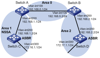
Networking and Configuration Requirements
The following figure shows an AS is split into three areas, where all switches run OSPF. Switch A and Switch B act as ABRs to forward routing information between areas. Switch D acts as the ASBR to redistribute routes (static routes).
It is required to configure Area 1 as an NSSA area, and configure Router C as the ASBR to redistribute static routes into the AS.
Applicable Product Matrix
|
Product series |
Software version |
Hardware version |
|
S3610 Series Ethernet Switches |
Release 5301 Release 5303 |
All versions |
|
S5510 Series Ethernet Switches |
Release 5301 Release 5303 |
All versions |
|
S5500-EI Series Ethernet Switches |
Release 2102 |
All versions |
|
S7500E Series Ethernet Switches |
Release 6100 Release 6300 |
All versions |
Configuration Procedure
1) Configure IP addresses for interfaces (omitted).
2) Configure OSPF basic functions (refer to Configuring OSPF Basic Functions).
3) Configure Switch D to import external static routes (refer to Configuring an OSPF Stub Area)
4) Configure Area 1 as an NSSA area.
# Configure Switch A.
[SwitchA] ospf
[SwitchA-ospf-1] area 1
[SwitchA-ospf-1-area-0.0.0.1] nssa default-route-advertise no-summary
[SwitchA-ospf-1-area-0.0.0.0] quit
[SwitchA-ospf-1] quit
# Configure Switch C.
[SwitchC] ospf
[SwitchC-ospf-1] area 1
[SwitchC-ospf-1-area-0.0.0.1] nssa
[SwitchC-ospf-1-area-0.0.0.1] quit
[SwitchC-ospf-1] quit
![]()
It is recommended to configure the nssa command with the keyword default-route-advertise no-summary on Switch A (an ABR) to reduce the routing table size on NSSA routers. On other NSSA routers, using the nssa command is ok.
# Display OSPF routing information on Switch C.
[SwitchC] display ospf routing
OSPF Process 1 with Router ID 172.16.1.1
Routing Tables
Routing for Network
Destination Cost Type NextHop AdvRouter Area
0.0.0.0/0 1563 Inter-area 192.168.1.1 192.168.0.1 0.0.0.1
172.16.1.0/24 1 Stub 172.16.1.1 172.16.1.1 0.0.0.1
192.168.1.0/24 1562 Stub 192.168.1.2 172.16.1.1 0.0.0.1
Total Nets: 3
Intra Area: 2 Inter Area: 1 ASE: 0 NSSA: 0
5) Configure Switch C to redistribute static routes.
[SwitchC] ip route-static 100.0.0.0 8 null 0
[SwitchC] ospf
[SwitchC-ospf-1] import-route static
[SwitchC-ospf-1] quit
# Display OSPF routing information on Switch D.
[SwitchD-ospf-1] display ospf routing
OSPF Process 1 with Router ID 172.17.1.1
Routing Tables
Routing for Network
Destination Cost Type NextHop AdvRouter Area
172.16.1.0/24 4687 Inter-area 192.168.2.1 192.168.0.2 0.0.0.2
172.17.1.0/24 1 Stub 172.17.1.1 172.17.1.1 0.0.0.2
192.168.1.0/24 4686 Inter-area 192.168.2.1 192.168.0.2 0.0.0.2
192.168.2.0/24 1562 Stub 192.168.2.2 172.17.1.1 0.0.0.2
192.168.0.0/24 3124 Inter-area 192.168.2.1 192.168.0.2 0.0.0.2
Routing for ASEs
Destination Cost Type Tag NextHop AdvRouter
100.0.0.0/8 10 Type2 1 192.168.2.1 192.168.0.1
Routing for NSSAs
Destination Cost Type Tag NextHop AdvRouter
Total Nets: 6
Intra Area: 2 Inter Area: 3 ASE: 1 NSSA: 0
![]()
You can see on Switch D an external route imported from the NSSA area.
Complete Configuration
l Configure Switch A
#
vlan 100
#
vlan 200
#
interface Vlan-interface100
ip address 192.168.0.1 255.255.255.0
#
interface Vlan-interface200
ip address 192.168.1.1 255.255.255.0
#
ospf 1
area 0.0.0.0
network 192.168.0.0 0.0.0.255
area 0.0.0.1
network 192.168.1.0 0.0.0.255
nssa default-route-advertise no-summary
#
l Configure Switch B
#
vlan 100
#
vlan 200
#
interface Vlan-interface100
ip address 192.168.0.2 255.255.255.0
#
interface Vlan-interface200
ip address 192.168.2.1 255.255.255.0
#
ospf 1
area 0.0.0.0
network 192.168.0.0 0.0.0.255
area 0.0.0.2
network 192.168.2.0 0.0.0.255
#
l Configure Switch C
#
vlan 200
#
vlan 300
#
interface Vlan-interface200
ip address 192.168.1.2 255.255.255.0
#
interface Vlan-interface300
ip address 172.16.1.1 255.255.255.0
#
ospf 1
area 0.0.0.1
network 192.168.1.0 0.0.0.255
network 172.16.1.0 0.0.0.255
nssa
import-route static
#
ip route-static 100.0.0.0 255.0.0.0 NULL0
#
l Configure Switch D
#
vlan 200
#
vlan 300
#
interface Vlan-interface200
ip address 192.168.2.2 255.255.255.0
#
interface Vlan-interface300
ip address 172.17.1.1 255.255.255.0
#
ospf 1
area 0.0.0.2
network 192.168.2.0 0.0.0.255
network 172.17.1.0 0.0.0.255
import-route static
#
ip route-static 200.0.0.0 255.0.0.0 NULL0
#
Configuration Guidelines
It is required to use the nssa command on routers attached to an NSSA area.
Configuring OSPF DR Election
On broadcast or NBMA networks, any two routers exchange routing information with each other. If n routers are present on a network, n(n-1)/2 adjacencies are required. Any change on a router in the network generates traffic for routing information synchronization, consuming network resources. The Designated Router is defined to solve the problem. All other routers on the network send routing information to the DR, which is responsible for advertising link state information.
If the DR fails to work, routers on the network have to elect another DR and synchronize information with the new DR. It is time-consuming and prone to routing calculation errors. The Backup Designated Router (BDR) is introduced to reduce the synchronization period.
The BDR is elected along with the DR and establishes adjacencies for routing information exchange with all other routers. When the DR fails, the BDR will become the new DR in a very short period by avoiding adjacency establishment and DR reelection. Meanwhile, other routers elect another BDR, which requires a relatively long period but has no influence on routing calculation.
Other routers, also known as DRothers, establish no adjacency and exchange no routing information with each other, thus reducing the number of adjacencies on broadcast and NBMA networks.
Network Diagram
Figure 1-10 Network diagram for OSPF virtual link configuration
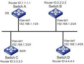
Networking and Configuration Requirements
l In the following figure, OSPF Switches A, B, C and D reside on the same network segment.
l It is required to configure Switch A as the DR, and configure Switch C as the BDR.
Applicable Product Matrix
|
Product series |
Software version |
Hardware version |
|
S3610 Series Ethernet Switches |
Release 5301 Release 5303 |
All versions |
|
S5510 Series Ethernet Switches |
Release 5301 Release 5303 |
All versions |
|
S5500-EI Series Ethernet Switches |
Release 2102 |
All versions |
|
S7500E Series Ethernet Switches |
Release 6100 Release 6300 |
All versions |
Configuration Procedure
1) Configure IP addresses for interfaces (omitted)
2) Configure OSPF basic functions
# Configure Switch A. Enable OSPF on it and assign it router ID 1.1.1.1.
<SwitchA> system-view
[SwitchA] router id 1.1.1.1
[SwitchA] ospf
[SwitchA-ospf-1] area 0
[SwitchA-ospf-1-area-0.0.0.0] network 192.168.1.0 0.0.0.255
[SwitchA-ospf-1-area-0.0.0.0] quit
[SwitchA-ospf-1] quit
# Configure Switch B. Enable OSPF on it and assign it router ID 2.2.2.2.
<SwitchB> system-view
[SwitchB] router id 2.2.2.2
[SwitchB] ospf
[SwitchB-ospf-1] area 0
[SwitchB-ospf-1-area-0.0.0.0] network 192.168.1.0 0.0.0.255
[SwitchB-ospf-1-area-0.0.0.0] quit
[SwitchB-ospf-1] quit
# Configure Switch C. Enable OSPF on it and assign it router ID 3.3.3.3.
<SwitchC> system-view
[SwitchC] router id 3.3.3.3
[SwitchC] ospf
[SwitchC-ospf-1] area 0
[SwitchC-ospf-1-area-0.0.0.0] network 192.168.1.0 0.0.0.255
[SwitchC-ospf-1-area-0.0.0.0] quit
[SwitchC-ospf-1] quit
# Configure Switch D. Enable OSPF on it and assign it router ID 4.4.4.4.
<SwitchD> system-view
[SwitchD] router id 4.4.4.4
[SwitchD] ospf
[SwitchD-ospf-1] area 0
[SwitchD-ospf-1-area-0.0.0.0] network 192.168.1.0 0.0.0.255
[SwitchD-ospf-1-area-0.0.0.0] quit
[SwitchD-ospf-1] quit
# Display OSPF neighbor information on Switch A.
[SwitchA] display ospf peer verbose
OSPF Process 1 with Router ID 1.1.1.1
Neighbors
Area 0.0.0.0 interface 192.168.1.1(Vlan-interface1)'s neighbors
Router ID: 2.2.2.2 Address: 192.168.1.2 GR State: Normal
State: 2-Way Mode: None Priority: 1
DR: 192.168.1.4 BDR: 192.168.1.3 MTU: 0
Dead timer due in 38 sec
Neighbor is up for 00:01:31
Authentication Sequence: [ 0 ]
Neighbor state change count: 2
Router ID: 3.3.3.3 Address: 192.168.1.3 GR State: Normal
State: Full Mode: Nbr is Master Priority: 1
DR: 192.168.1.4 BDR: 192.168.1.3 MTU: 0
Dead timer due in 31 sec
Neighbor is up for 00:01:28
Authentication Sequence: [ 0 ]
Neighbor state change count: 2
Router ID: 4.4.4.4 Address: 192.168.1.4 GR State: Normal
State: Full Mode: Nbr is Master Priority: 1
DR: 192.168.1.4 BDR: 192.168.1.3 MTU: 0
Dead timer due in 31 sec
Neighbor is up for 00:01:28
Authentication Sequence: [ 0 ]
Neighbor state change count: 2
Switch D becomes the DR, and Switch C is the BDR.
3) Configure router priorities on interfaces
# Configure Switch A.
[SwitchA] interface vlan-interface 1
[RouterA-Vlan-interface1] ospf dr-priority 100
[RouterA-Vlan-interface1] quit
# Configure Switch B.
[SwitchB] interface vlan-interface 1
[SwitchB-Vlan-interface1] ospf dr-priority 0
[SwitchB-Vlan-interface1] quit
# Configure Switch C.
[SwitchC] interface vlan-interface 1
[SwitchC-Vlan-interface1] ospf dr-priority 2
[SwitchC-Vlan-interface] quit
# Display neighbor information on Switch D.
[SwitchD] display ospf peer verbose
OSPF Process 1 with Router ID 4.4.4.4
Neighbors
Area 0.0.0.0 interface 192.168.1.4(Vlan-interface1)'s neighbors
Router ID: 1.1.1.1 Address: 192.168.1.1 GR State: Normal
State: Full Mode:Nbr is Slave Priority: 100
DR: 192.168.1.4 BDR: 192.168.1.3 MTU: 0
Dead timer due in 31 sec
Neighbor is up for 00:11:17
Authentication Sequence: [ 0 ]
Neighbor state change count: 3
Router ID: 2.2.2.2 Address: 192.168.1.2 GR State: Normal
State: Full Mode:Nbr is Slave Priority: 0
DR: 192.168.1.4 BDR: 192.168.1.3 MTU: 0
Dead timer due in 35 sec
Neighbor is up for 00:11:19
Authentication Sequence: [ 0 ]
Neighbor state change count: 3
Router ID: 3.3.3.3 Address: 192.168.1.3 GR State: Normal
State: Full Mode:Nbr is Slave Priority: 2
DR: 192.168.1.4 BDR: 192.168.1.3 MTU: 0
Dead timer due in 33 sec
Neighbor is up for 00:11:15
Authentication Sequence: [ 0 ]
Neighbor state change count: 3
The DR and BDR have no change.
![]()
In the above output, you can find the priority configuration does not take effect immediately.
4) Restart OSPF process (omitted)
# Display neighbor information on Switch D.
[SwitchD] display ospf peer verbose
OSPF Process 1 with Router ID 4.4.4.4
Neighbors
Area 0.0.0.0 interface 192.168.1.4(Vlan-interface1)'s neighbors
Router ID: 1.1.1.1 Address: 192.168.1.1 GR State: Normal
State: Full Mode: Nbr is Slave Priority: 100
DR: 192.168.1.1 BDR: 192.168.1.3 MTU: 0
Dead timer due in 39 sec
Neighbor is up for 00:01:40
Authentication Sequence: [ 0 ]
Neighbor state change count: 2
Router ID: 2.2.2.2 Address: 192.168.1.2 GR State: Normal
State: 2-Way Mode: None Priority: 0
DR: 192.168.1.1 BDR: 192.168.1.3 MTU: 0
Dead timer due in 35 sec
Neighbor is up for 00:01:44
Authentication Sequence: [ 0 ]
Neighbor state change count: 2
Router ID: 3.3.3.3 Address: 192.168.1.3 GR State: Normal
State: Full Mode: Nbr is Slave Priority: 2
DR: 192.168.1.1 BDR: 192.168.1.3 MTU: 0
Dead timer due in 39 sec
Neighbor is up for 00:01:41
Authentication Sequence: [ 0 ]
Neighbor state change count: 2
Switch A becomes the DR, and Switch C is the BDR.
![]()
If the neighbor state is full, it means Switch D has established the adjacency with the neighbor. If the neighbor state is 2-way, it means the two switches are neither the DR nor the BDR, and they do not exchange LSAs.
# Display OSPF interface information.
[SwitchA] display ospf interface
OSPF Process 1 with Router ID 1.1.1.1
Interfaces
Area: 0.0.0.0
IP Address Type State Cost Pri DR BDR
192.168.1.1 Broadcast DR 1 100 192.168.1.1 192.168.1.3
[SwitchB] display ospf interface
OSPF Process 1 with Router ID 2.2.2.2
Interfaces
Area: 0.0.0.0
IP Address Type State Cost Pri DR BDR
192.168.1.2 Broadcast DROther 1 0 192.168.1.1 192.168.1.3
![]()
The interface state DROther means the interface is not the DR/BDR.
Complete Configuration
l Configure Switch A
#
router id 1.1.1.1
#
interface Vlan-interface1
ip address 192.168.1.1 255.255.255.0
ospf dr-priority 100
#
ospf 1
area 0.0.0.0
network 192.168.1.0 0.0.0.255
#
l Configure Switch B
#
router id 2.2.2.2
#
interface Vlan-interface1
ip address 192.168.1.2 255.255.255.0
ospf dr-priority 0
#
ospf 1
area 0.0.0.0
network 192.168.1.0 0.0.0.255
#
l Configure Switch C
#
router id 3.3.3.3
#
interface Vlan-interface1
ip address 192.168.1.3 255.255.255.0
ospf dr-priority 2
#
ospf 1
area 0.0.0.0
network 192.168.1.0 0.0.0.255
#
l Configure Switch D
#
router id 4.4.4.4
#
interface Vlan-interface1
ip address 192.168.1.4 255.255.255.0
#
ospf 1
area 0.0.0.0
network 192.168.1.0 0.0.0.255
#
Configuration Guidelines
l The DR election is available on broadcast, NBMA interfaces rather than P2P, or P2MP interfaces.
l A DR is an interface of a router and belongs to a single network segment. The router’s other interfaces may be a BDR or DRother.
l After DR/BDR election and then a new router joins, it cannot become the DR immediately even if it has the highest priority on the network.
l The DR may not be the router with the highest priority in a network, and the BDR may not be the router with the second highest priority.
Configuring an OSPF Virtual Link
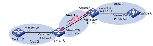
Each AS has a backbone area, which is responsible for distributing routing information between none-backbone areas. Routing information between non-backbone areas must be forwarded by the backbone area. Therefore, OSPF requires that:
l All non-backbone areas must maintain connectivity to the backbone area.
l The backbone area itself must maintain connectivity.
In practice, due to physical limitations, the requirements may not be satisfied. In this case, configuring OSPF virtual links is a solution.
A virtual link is established between two area border routers via a non-backbone area and is configured on both ABRs to take effect. The area that provides the non-backbone area internal route for the virtual link is a “transit area”.
Network Diagram
Figure 1-11 Network diagram for OSPF GR configuration
Networking and Configuration Requirements
l In the following figure, Area 2 has no direct connection to Area 0, and Area 1 acts as the Transit Area to connect Area 2 to Area 0 via a configured virtual link between Switch B and Switch C.
l After configuration, Switch B can learn routes to Area 2.
Applicable Product Matrix
|
Product series |
Software version |
Hardware version |
|
S3610 Series Ethernet Switches |
Release 5301 Release 5303 |
All versions |
|
S5510 Series Ethernet Switches |
Release 5301 Release 5303 |
All versions |
|
S5500-EI Series Ethernet Switches |
Release 2102 |
All versions |
|
S7500E Series Ethernet Switches |
Release 6100 Release 6300 |
All versions |
Configuration Procedure
1) Configure IP addresses for interfaces (omitted)
2) Configure OSPF basic functions
# Configure Switch A. Enable OSPF on it and assign it router ID 1.1.1.1.
<SwitchA> system-view
[SwitchA] ospf 1 router-id 1.1.1.1
[SwitchA-ospf-1] area 0
[SwitchA-ospf-1-area-0.0.0.0] network 10.1.1.0 0.0.0.255
[SwitchA-ospf-1-area-0.0.0.0] quit
# Configure Switch B. Enable OSPF on it and assign it router ID 2.2.2.2.
<SwitchB> system-view
[SwitchB] ospf 1 router-id 2.2.2.2
[SwitchB-ospf-1] area 0
[SwitchB-ospf-1-area-0.0.0.0] network 10.1.1.0 0.0.0.255
[SwitchB-ospf-1-area-0.0.0.0] quit
[SwitchB-ospf-1] area 1
[SwitchB–ospf-1-area-0.0.0.1] network 10.2.1.0 0.0.0.255
[SwitchB–ospf-1-area-0.0.0.1] quit
# Configure Switch C. Enable OSPF on it and assign it router ID 3.3.3.3.
<SwitchC> system-view
[SwitchC] ospf 1 router-id 3.3.3.3
[SwitchC-ospf-1] area 1
[SwitchC-ospf-1-area-0.0.0.1] network 10.2.1.0 0.0.0.255
[SwitchC-ospf-1-area-0.0.0.1] quit
[SwitchC-ospf-1] area 2
[SwitchC–ospf-1-area-0.0.0.2] network 10.3.1.0 0.0.0.255
[SwitchC–ospf-1-area-0.0.0.2] quit
# Configure Switch D. Enable OSPF on it and assign it router ID 4.4.4.4.
<SwitchD> system-view
[SwitchD] ospf 1 router-id 4.4.4.4
[SwitchD-ospf-1] area 2
[SwitchD-ospf-1-area-0.0.0.2] network 10.3.1.0 0.0.0.255
[SwitchD-ospf-1-area-0.0.0.2] quit
# Display the OSPF routing table of Switch B.
[SwitchB] display ospf routing
OSPF Process 1 with Router ID 2.2.2.2
Routing Tables
Routing for Network
Destination Cost Type NextHop AdvRouter Area
10.2.1.0/24 2 Transit 10.2.1.1 3.3.3.3 0.0.0.1
10.1.1.0/24 2 Transit 10.1.1.2 2.2.2.2 0.0.0.0
Total Nets: 2
Intra Area: 2 Inter Area: 0 ASE: 0 NSSA: 0
![]()
Since Area 0 has no direct connection to Area 2, the routing table of Switch B has no route to Area 2.
3) Configure a virtual link
# Configure Switch B.
[SwitchB] ospf
[SwitchB-ospf-1] area 1
[SwitchB-ospf-1-area-0.0.0.1] vlink-peer 3.3.3.3
[SwitchB-ospf-1-area-0.0.0.1] quit
[SwitchB-ospf-1] quit
# Configure Switch C.
[SwitchC] ospf 1
[SwitchC-ospf-1] area 1
[SwitchC-ospf-1-area-0.0.0.1] vlink-peer 2.2.2.2
[SwitchC-ospf-1-area-0.0.0.1] quit
# Display the OSPF routing table of Switch B.
[SwitchB] display ospf routing
OSPF Process 1 with Router ID 2.2.2.2
Routing Tables
Routing for Network
Destination Cost Type NextHop AdvRouter Area
10.2.1.0/24 2 Transit 10.2.1.1 3.3.3.3 0.0.0.1
10.3.1.0/24 5 Inter 10.2.1.2 3.3.3.3 0.0.0.0
10.1.1.0/24 2 Transit 10.1.1.2 2.2.2.2 0.0.0.0
Total Nets: 3
Intra Area: 2 Inter Area: 1 ASE: 0 NSSA: 0
Switch B has learned the route 10.3.1.0/24 to Area 2.
Complete Configuration
l Configure Switch A.
#
vlan 300
#
interface Vlan-interface300
ip address 10.1.1.1 255.255.255.0
#
ospf 1 router-id 1.1.1.1
area 0.0.0.0
network 10.1.1.0 0.0.0.255
#
l Configure Switch B.
#
vlan 200
#
vlan 300
#
interface Vlan-interface200
ip address 10.2.1.1 255.255.255.0
#
interface Vlan-interface300
ip address 10.1.1.2 255.255.255.0
#
ospf 1 router-id 2.2.2.2
area 0.0.0.0
network 10.1.1.0 0.0.0.255
area 0.0.0.1
network 10.2.1.0 0.0.0.255
vlink-peer 3.3.3.3
#
l Configure Switch C.
#
vlan 100
#
vlan 200
#
interface Vlan-interface100
ip address 10.3.1.2 255.255.255.0
#
interface Vlan-interface200
ip address 10.2.1.2 255.255.255.0
#
ospf 1 router-id 3.3.3.3
area 0.0.0.1
network 10.2.1.0 0.0.0.255
vlink-peer 2.2.2.2
area 0.0.0.2
network 10.3.1.0 0.0.0.255
#
l Configure Switch D.
#
vlan 100
#
interface Vlan-interface100
ip address 10.3.1.1 255.255.255.0
#
ospf 1 router-id 4.4.4.4
area 0.0.0.2
network 10.3.1.0 0.0.0.255
#
Configuration Guidelines
l For a virtual link to take effect, the vlink-peer command must be configured on both ends of the virtual link, and the hello and dead parameter configurations must be identical on both ends of the link
l Virtual links cannot transit Stub areas.
l Virtual links cannot transit NSSA areas.
Configuring OSPF GR
After an OSPF GR Restarter restarts OSPF, it needs to perform the following two tasks in order to re-synchronize its LSDB with its neighbors.
l To obtain once again effective OSPF neighbor information without changing the adjacencies.
l To obtain once again LSDB contents.
Before the restart, the GR Restarter originates Grace-LSAs to negotiate the GR capability. During the restart, the GR Helpers continue to advertise their adjacencies with the GR Restarter.
After the restart, the GR Restarter will send an OSPF GR signal to its neighbors that will not reset their adjacencies with it. In this way, the GR Restarter can restore the neighbor table upon receiving the responses from neighbors.
After reestablishing neighbor relationships, the GR Restarter will synchronize the LSDB and exchange routing information with all adjacent GR-capable neighbors. After that, the GR Restarter will update its own routing table and forwarding table based on the new routing information and remove the stale routes. In this way, the OSPF routing convergence is complete.
Network Diagram
Figure 1-12 Network diagram for route filtering configuration
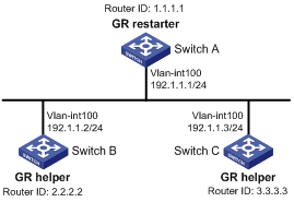
Networking and Configuration Requirements
l Switch A, Switch B and Switch C that belong to the same autonomous system and the same OSPF routing domain are GR capable.
l Switch A acts as the non IETF standard GR Restarter whereas Switch B and Switch C are the GR Helpers and re-synchronize their LSDB with Switch A through OOB( out-of-band ) communication of GR.
Applicable Product Matrix
|
Product series |
Software version |
Hardware version |
|
S3610 Series Ethernet Switches |
Release 5301 Release 5303 |
All versions |
|
S5510 Series Ethernet Switches |
Release 5301 Release 5303 |
All versions |
|
S5500-EI Series Ethernet Switches |
Release 2102 |
All versions |
Configuration Procedure
1) # Configure Switch A, enable OSPF on it, and assign it router ID 1.1.1.1.
<SwitchA> system-view
[SwitchA] interface vlan-interface 100
[SwitchA-Vlan-interface100] ip address 192.1.1.1 255.255.255.0
[SwitchA-Vlan-interface100] quit
[SwitchA] router id 1.1.1.1
[SwitchA] ospf 100
[SwitchA-ospf-100] enable link-local-signaling
[SwitchA-ospf-100] enable out-of-band-resynchronization
[RouterA-ospf-100] graceful-restart
[SwitchA-ospf-100] area 0
[SwitchA-ospf-100-area-0.0.0.0] network 192.1.1.0 0.0.0.255
[SwitchA-ospf-100-area-0.0.0.0] return
2) Configure Switch B. Enable OSPF on it, and assign it router ID 2.2.2.2.
<SwitchB> system-view
[SwitchB] acl number 2000
[SwitchB-acl-basic-2000] rule 10 permit source 192.1.1.1 0.0.0.0
[SwitchB-acl-basic-2000] quit
[SwitchB] interface vlan-interface 100
[SwitchB-Vlan-interface100] ip address 192.1.1.2 255.255.255.0
[SwitchB-Vlan-interface100] quit
[SwitchB] router id 2.2.2.2
[SwitchB] ospf 100
[SwitchB-ospf-100] enable link-local-signaling
[SwitchB-ospf-100] enable out-of-band-resynchronization
[SwitchB-ospf-100] graceful-restart help 2000
[SwitchB-ospf-100] area 0
[SwitchB-ospf-100-area-0.0.0.0] network 192.1.1.0 0.0.0.255
[SwitchB-ospf-100-area-0.0.0.0] quit
3) Configure Switch C. Enable OSPF on it, and assign it router ID 3.3.3.3.
<SwitchC> system-view
[SwitchC] interface vlan-interface 100
[SwitchC-Vlan-interface100] ip address 192.1.1.3 255.255.255.0
[SwitchC-Vlan-interface100] quit
[SwitchC] router id 3.3.3.3
[SwitchC] ospf 100
[SwitchC-ospf-100] enable link-local-signaling
[SwitchC-ospf-100] enable out-of-band-resynchronization
[SwitchC-ospf-100] area 0
[SwitchC-ospf-100-area-0.0.0.0] network 192.1.1.0 0.0.0.255
[SwitchC-ospf-100-area-0.0.0.0] quit
4) Verify the configuration
# After the configurations on Switch A, Switch B and Switch C are completed and the switches are running steadily, perform OSPF GR on Switch A.
<SwitchA> reset ospf 100 process graceful-restart
Complete Configuration
l Configure Switch A.
#
router id 1.1.1.1
#
vlan 100
#
interface Vlan-interface100
ip address 192.1.1.1 255.255.255.0
#
ospf 100
enable link-local-signaling
enable out-of-band-resynchronization
graceful-restart nonstandard
area 0.0.0.0
network 192.1.1.0 0.0.0.255
#
l Configure Switch B.
#
router id 2.2.2.2
#
vlan 100
#
acl number 2000
rule 10 permit source 192.1.1.1 0
#
interface Vlan-interface100
ip address 192.1.1.2 255.255.255.0
ospf dr-priority 0
#
ospf 100
enable link-local-signaling
enable out-of-band-resynchronization
graceful-restart help 2000
area 0.0.0.0
network 192.1.1.0 0.0.0.255
#
l Configure Switch C.
#
router id 3.3.3.3
#
vlan 100
#
interface Vlan-interface100
ip address 192.1.1.3 255.255.255.0
ospf dr-priority 2
#
ospf 100
enable link-local-signaling
enable out-of-band-resynchronization
area 0.0.0.0
network 192.1.1.0 0.0.0.255
#
Configuration Guidelines
For the IETF standard GR capable routers, ensure they have the following capabilities enabled:
l Opaque LSA advertisement
l IETF standard GR
For the non IETF standard GR capable routers, ensure they have the following capabilities enabled:
l link local signaling
l out of band re-synchronization
l Non IETF standard GR
Configuring Route Filtering
Network Diagram
Figure 1-13 Network diagram for IS-IS basic configuration
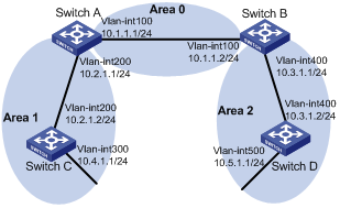
Networking and Configuration Requirements
l All the switches in the network run OSPF. The AS is divided into three areas.
l Switch A and Switch B work as ABRs.
l Configure Switch C as an ASBR to redistribute external routes (static routes), and configure a filter policy on Switch C to filter out redistributed route 3.1.3.0/24.
l Configure a route policy on Switch A to filter route 10.5.1.0/24.
Applicable Product Matrix
|
Product series |
Software version |
Hardware version |
|
S3610 Series Ethernet Switches |
Release 5301 Release 5303 |
All versions |
|
S5510 Series Ethernet Switches |
Release 5301 Release 5303 |
All versions |
|
S5500-EI Series Ethernet Switches |
Release 2102 |
All versions |
|
S7500E Series Ethernet Switches |
Release 6100 Release 6300 |
All versions |
Configuration Procedure
1) Configure IP addresses for interfaces (omitted)
2) Configure OSPF
# Configure Switch A.
<SwitchA> system-view
[SwitchA] ospf
[SwitchA-ospf-1] area 0
[SwitchA-ospf-1-area-0.0.0.0] network 10.1.1.0 0.0.0.255
[SwitchA-ospf-1-area-0.0.0.0] quit
[SwitchA-ospf-1] area 1
[SwitchA-ospf-1-area-0.0.0.1] network 10.2.1.0 0.0.0.255
[SwitchA-ospf-1-area-0.0.0.1] quit
[SwitchA-ospf-1] quit
# Configure Switch B.
<SwitchB> system-view
[SwitchB] ospf
[SwitchB-ospf-1] area 0
[SwitchB-ospf-1-area-0.0.0.0] network 10.1.1.0 0.0.0.255
[SwitchB-ospf-1-area-0.0.0.0] quit
[SwitchB-ospf-1] area 2
[SwitchB-ospf-1-area-0.0.0.2] network 10.3.1.0 0.0.0.255
[SwitchB-ospf-1-area-0.0.0.2] quit
[SwitchB-ospf-1] quit
# Configure Switch C.
<SwitchC> system-view
[SwitchC] ospf
[SwitchC-ospf-1] area 1
[SwitchC-ospf-1-area-0.0.0.1] network 10.2.1.0 0.0.0.255
[SwitchC-ospf-1-area-0.0.0.1] network 10.4.1.0 0.0.0.255
[SwitchC-ospf-1-area-0.0.0.1] quit
[SwitchC-ospf-1] quit
# Configure Switch D.
<SwitchD> system-view
[SwitchD] ospf
[SwitchD-ospf-1] area 2
[SwitchD-ospf-1-area-0.0.0.2] network 10.3.1.0 0.0.0.255
[SwitchD-ospf-1-area-0.0.0.2] network 10.5.1.0 0.0.0.255
[SwitchD-ospf-1-area-0.0.0.2] quit
[SwitchD-ospf-1] quit
3) Configure OSPF to redistribute routes.
# On Switch C, configure a static route destined for network 3.1.1.0/24.
[SwitchC] ip route-static 3.1.1.0 24 10.4.1.2
# On Switch C, configure a static route destined for network 3.1.2.0/24.
[SwitchC] ip route-static 3.1.2.0 24 10.4.1.2
# On Switch C, configure a static route destined for network 3.1.3.0/24.
[SwitchC] ip route-static 3.1.3.0 24 10.4.1.2
# On Switch C, configure OSPF to redistribute static routes.
[SwitchC] ospf 1
[SwitchC-ospf-1] import-route static
[SwitchC-ospf-1] quit
# Display the OSPF routing table of Switch A.
[SwitchA] display ip routing-table
Routing Tables: Public
Destinations : 12 Routes : 12
Destination/Mask Proto Pre Cost NextHop Interface
3.1.1.0/24 O_ASE 150 1 10.2.1.2 Vlan200
3.1.2.0/24 O_ASE 150 1 10.2.1.2 Vlan200
3.1.3.0/24 O_ASE 150 1 10.2.1.2 Vlan200
10.1.1.0/24 Direct 0 0 10.1.1.1 Vlan200
10.1.1.1/32 Direct 0 0 127.0.0.1 InLoop0
10.2.1.0/24 Direct 0 0 10.2.1.1 Vlan200
10.2.1.1/32 Direct 0 0 127.0.0.1 InLoop0
10.3.1.0/24 OSPF 10 4 10.1.1.2 Vlan100
10.4.1.0/24 OSPF 10 13 10.2.1.2 Vlan200
10.5.1.0/24 OSPF 10 14 10.1.1.2 Vlan100
127.0.0.0/8 Direct 0 0 127.0.0.1 InLoop0
127.0.0.1/32 Direct 0 0 127.0.0.1 InLoop0
4) On Switch C, filter out route 3.1.3.0/24.
# Configure the IPv4 prefix list.
[SwitchC] ip ip-prefix prefix1 index 1 deny 3.1.3.0 24
[SwitchC] ip ip-prefix prefix1 index 2 permit 3.1.1.0 24
[SwitchC] ip ip-prefix prefix1 index 3 permit 3.1.2.0 24
# Reference the prefix list to filter out route 3.1.3.0/24.
[SwitchC] ospf 1
[SwitchC-ospf-1] filter-policy ip-prefix prefix1 export static
# Display the OSPF routing table of Switch A.
[SwitchA] display ip routing-table
Routing Tables: Public
Destinations : 11 Routes : 11
Destination/Mask Proto Pre Cost NextHop Interface
3.1.1.0/24 O_ASE 150 1 10.2.1.2 Vlan200
3.1.2.0/24 O_ASE 150 1 10.2.1.2 Vlan200
10.1.1.0/24 Direct 0 0 10.1.1.1 Vlan100
10.1.1.1/32 Direct 0 0 127.0.0.1 InLoop0
10.2.1.0/24 Direct 0 0 10.2.1.1 Vlan200
10.2.1.1/32 Direct 0 0 127.0.0.1 InLoop0
10.3.1.0/24 OSPF 10 4 10.1.1.2 Vlan100
10.4.1.0/24 OSPF 10 13 10.2.1.2 Vlan200
10.5.1.0/24 OSPF 10 14 10.1.1.2 Vlan100
127.0.0.0/8 Direct 0 0 127.0.0.1 InLoop0
127.0.0.1/32 Direct 0 0 127.0.0.1 InLoop0
The route destined for network 3.1.3.0/24 is filtered out.
5) On Switch A, filter out the route 10.5.1.1/24.
# Configure the ACL on Switch A.
[SwitchA] acl number 2000
[SwitchA-acl-basic-2000] rule 0 deny source 10.5.1.0 0.0.0.255
[SwitchA-acl-basic-2000] rule 1 permit source any
[SwitchA-acl-basic-2000] quit
# Use the ACL to filter route 10.5.1.0/24.
[SwitchA] ospf 1
[SwitchA-ospf-1] filter-policy 2000 import
[SwitchA-ospf-1] quit
# Display the OSPF routing table of Switch A.
[SwitchA] display ip routing-table
Routing Tables: Public
Destinations : 10 Routes : 10
Destination/Mask Proto Pre Cost NextHop Interface
3.1.1.0/24 O_ASE 150 1 10.2.1.2 Vlan200
3.1.2.0/24 O_ASE 150 1 10.2.1.2 Vlan200
10.1.1.0/24 Direct 0 0 10.1.1.1 Vlan100
10.1.1.1/32 Direct 0 0 127.0.0.1 InLoop0
10.2.1.0/24 Direct 0 0 10.2.1.1 Vlan200
10.2.1.1/32 Direct 0 0 127.0.0.1 InLoop0
10.3.1.0/24 OSPF 10 4 10.1.1.2 Vlan100
10.4.1.0/24 OSPF 10 13 10.2.1.2 Vlan200
127.0.0.0/8 Direct 0 0 127.0.0.1 InLoop0
127.0.0.1/32 Direct 0 0 127.0.0.1 InLoop0
The route destined for 10.5.1.1/24 is filtered out.
Complete Configuration
l Configure Switch A.
#
acl number 2000
rule 0 deny source 10.5.1.0 0.0.0.255
rule 1 permit
#
vlan 100
#
vlan 200
#
interface Vlan-interface100
ip address 10.1.1.1 255.255.255.0
#
interface Vlan-interface200
ip address 10.2.1.1 255.255.255.0
#
ospf 1
filter-policy 2000 import
area 0.0.0.0
network 10.1.1.0 0.0.0.255
area 0.0.0.1
network 10.2.1.0 0.0.0.255
#
l Configure Switch B.
#
vlan 100
#
vlan 400
#
interface Vlan-interface100
ip address 10.1.1.2 255.255.255.0
#
interface Vlan-interface400
ip address 10.3.1.1 255.255.255.0
#
ospf 1
area 0.0.0.0
network 10.1.1.0 0.0.0.255
area 0.0.0.2
network 10.3.1.0 0.0.0.255
#
l Configure Switch C.
#
vlan 200
#
vlan 300
#
interface Vlan-interface200
ip address 10.2.1.2 255.255.255.0
#
interface Vlan-interface300
ip address 10.4.1.1 255.255.255.0
#
ospf 1
filter-policy ip-prefix prefix1 export static
import-route static
area 0.0.0.1
network 10.2.1.0 0.0.0.255
network 10.4.1.0 0.0.0.255
#
ip ip-prefix prefix1 index 1 deny 3.1.3.0 24
ip ip-prefix prefix1 index 2 permit 3.1.1.0 24
ip ip-prefix prefix1 index 3 permit 3.1.2.0 24
#
ip route-static 3.1.1.0 255.255.255.0 10.4.1.2
ip route-static 3.1.2.0 255.255.255.0 10.4.1.2
ip route-static 3.1.3.0 255.255.255.0 10.4.1.2
#
l Configure Switch D.
#
vlan 400
#
vlan 500
#
interface Vlan-interface400
ip address 10.3.1.2 255.255.255.0
#
interface Vlan-interface500
ip address 10.5.1.1 255.255.255.0
#
ospf 1
area 0.0.0.2
network 10.3.1.0 0.0.0.255
network 10.5.1.0 0.0.0.255
#
Configuration Guidelines
None
Configuring IS-IS Basic Functions
Intermediate System-to-Intermediate System (IS-IS) is a dynamic routing protocol designed by the International Organization for Standardization (ISO) to operate on the connectionless network protocol (CLNP).
The IS-IS routing protocol has been modified and extended in RFC 1195 by the International Engineer Task Force (IETF) for application in both TCP/IP and OSI reference models, and the new one is called Integrated IS-IS or Dual IS-IS.
IS-IS is an Interior Gateway Protocol (IGP) used within an Autonomous System. It adopts the Shortest Path First (SPF) algorithm for route calculation.
Network Diagram
Figure 1-14 Network diagram for IS-IS DIS election configuration
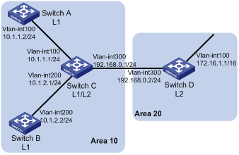
Networking and Configuration Requirements
As shown in Network diagram for IS-IS basic configuration, Switch A, B, C and Switch D reside in an IS-IS AS. Switch A and B are Level-1 switches, Switch D is a Level-2 switch and Switch C is a Level-1-2 switch. Switch A, B and C are in Area 10, while Switch D is in Area 20.
It is required that IP reachability be achieved between them through IS-IS.
Applicable Product Matrix
|
Product series |
Software version |
Hardware version |
|
S3610 Series Ethernet Switches |
Release 5301 Release 5303 |
All versions |
|
S5510 Series Ethernet Switches |
Release 5301 Release 5303 |
All versions |
|
S5500-EI Series Ethernet Switches |
Release 2102 |
All versions |
|
S7500E Series Ethernet Switches |
Release 6100 Release 6300 |
All versions |
Configuration Procedure
1) Configure IP addresses for interfaces (omitted)
2) Configure IS-IS
# Configure Switch A.
<SwitchA> system-view
[SwitchA] isis 1
[SwitchA-isis-1] is-level level-1
[SwitchA-isis-1] network-entity 10.0000.0000.0001.00
[SwitchA-isis-1] quit
[SwitchA] interface vlan-interface 100
[SwitchA-Vlan-interface100] isis enable 1
[SwitchA-Vlan-interface100] quit
# Configure Switch B.
<SwitchB> system-view
[SwitchB] isis 1
[SwitchB-isis-1] is-level level-1
[SwitchB-isis-1] network-entity 10.0000.0000.0002.00
[SwitchB-isis-1] quit
[SwitchB] interface vlan-interface 200
[SwitchB-Vlan-interface200] isis enable 1
[SwitchB-Vlan-interface200] quit
# Configure Switch C.
<SwitchC> system-view
[SwitchC] isis 1
[SwitchC-isis-1] network-entity 10.0000.0000.0003.00
[SwitchC-isis-1] quit
[SwitchC] interface vlan-interface 100
[SwitchC-Vlan-interface100] isis enable 1
[SwitchC-Vlan-interface100] quit
[SwitchC] interface vlan-interface 200
[SwitchC-Vlan-interface200] isis enable 1
[SwitchC-Vlan-interface200] quit
[SwitchC] interface vlan-interface 300
[SwitchC-Vlan-interface300] isis enable 1
[SwitchC-Vlan-interface300] quit
# Configure Switch D.
<SwitchD> system-view
[SwitchD] isis 1
[SwitchD-isis-1] is-level level-2
[SwitchD-isis-1] network-entity 20.0000.0000.0004.00
[SwitchD-isis-1] quit
[SwitchD] interface vlan-interface 100
[SwitchD-Vlan-interface100] isis enable 1
[SwitchD-Vlan-interface100] quit
[SwitchD] interface vlan-interface 300
[SwitchD-Vlan-interface300] isis enable 1
[SwitchD-Vlan-interface300] quit
3) Verify the configuration
# Display the IS-IS LSDB of each switch to check the LSP integrity.
[SwitchA] display isis lsdb
Database information for ISIS(1)
--------------------------------
Level-1 Link State Database
LSPID Seq Num Checksum Holdtime Length ATT/P/OL
--------------------------------------------------------------------------
0000.0000.0001.00-00* 0x00000004 0xdf5e 1096 68 0/0/0
0000.0000.0002.00-00 0x00000004 0xee4d 1102 68 0/0/0
0000.0000.0002.01-00 0x00000001 0xdaaf 1102 55 0/0/0
0000.0000.0003.00-00 0x00000009 0xcaa3 1161 111 1/0/0
0000.0000.0003.01-00 0x00000001 0xadda 1112 55 0/0/0
*-Self LSP, +-Self LSP(Extended), ATT-Attached, P-Partition, OL-Overload
[SwitchB] display isis lsdb
Database information for ISIS(1)
--------------------------------
Level-1 Link State Database
LSPID Seq Num Checksum Holdtime Length ATT/P/OL
--------------------------------------------------------------------------
0000.0000.0001.00-00 0x00000006 0xdb60 988 68 0/0/0
0000.0000.0002.00-00* 0x00000008 0xe651 1189 68 0/0/0
0000.0000.0002.01-00* 0x00000005 0xd2b3 1188 55 0/0/0
0000.0000.0003.00-00 0x00000014 0x194a 1190 111 1/0/0
0000.0000.0003.01-00 0x00000002 0xabdb 995 55 0/0/0
*-Self LSP, +-Self LSP(Extended), ATT-Attached, P-Partition, OL-Overload
[SwitchC] display isis lsdb
Database information for ISIS(1)
--------------------------------
Level-1 Link State Database
LSPID Seq Num Checksum Holdtime Length ATT/P/OL
--------------------------------------------------------------------------
0000.0000.0001.00-00 0x00000006 0xdb60 847 68 0/0/0
0000.0000.0002.00-00 0x00000008 0xe651 1053 68 0/0/0
0000.0000.0002.01-00 0x00000005 0xd2b3 1052 55 0/0/0
0000.0000.0003.00-00* 0x00000014 0x194a 1051 111 1/0/0
0000.0000.0003.01-00* 0x00000002 0xabdb 854 55 0/0/0
*-Self LSP, +-Self LSP(Extended), ATT-Attached, P-Partition, OL-Overload
Level-2 Link State Database
LSPID Seq Num Checksum Holdtime Length ATT/P/OL
--------------------------------------------------------------------------
0000.0000.0003.00-00* 0x00000012 0xc93c 842 100 0/0/0
0000.0000.0004.00-00 0x00000026 0x331 1173 84 0/0/0
0000.0000.0004.01-00 0x00000001 0xee95 668 55 0/0/0
*-Self LSP, +-Self LSP(Extended), ATT-Attached, P-Partition, OL-Overload
[SwitchD] display isis lsdb
Database information for ISIS(1)
--------------------------------
Level-2 Link State Database
LSPID Seq Num Checksum Holdtime Length ATT/P/OL
--------------------------------------------------------------------------
0000.0000.0003.00-00 0x00000013 0xc73d 1003 100 0/0/0
0000.0000.0004.00-00* 0x0000003c 0xd647 1194 84 0/0/0
0000.0000.0004.01-00* 0x00000002 0xec96 1007 55 0/0/0
*-Self LSP, +-Self LSP(Extended), ATT-Attached, P-Partition, OL-Overload
# Display the IS-IS routing information of each switch. Level-1 switches should have a default route with the next hop being the Level-1-2 switch. The Level-2 switch should have both routing information of Level-1 and Level-2.
[SwitchA] display isis route
Route information for ISIS(1)
-----------------------------
ISIS(1) IPv4 Level-1 Forwarding Table
-------------------------------------
IPV4 Destination IntCost ExtCost ExitInterface NextHop Flags
--------------------------------------------------------------------------
10.1.1.0/24 10 NULL Vlan100 Direct D/L/-
10.1.2.0/24 20 NULL Vlan100 10.1.1.1 R/-/-
192.168.0.0/24 20 NULL Vlan100 10.1.1.1 R/-/-
0.0.0.0/0 10 NULL Vlan100 10.1.1.1 R/-/-
Flags: D-Direct, R-Added to RM, L-Advertised in LSPs, U-Up/Down Bit Set
[SwitchC] display isis route
Route information for ISIS(1)
-----------------------------
ISIS(1) IPv4 Level-1 Forwarding Table
-------------------------------------
IPV4 Destination IntCost ExtCost ExitInterface NextHop Flags
--------------------------------------------------------------------------
192.168.0.0/24 10 NULL Vlan300 Direct D/L/-
10.1.1.0/24 10 NULL Vlan100 Direct D/L/-
10.1.2.0/24 10 NULL Vlan200 Direct D/L/-
Flags: D-Direct, R-Added to RM, L-Advertised in LSPs, U-Up/Down Bit Set
ISIS(1) IPv4 Level-2 Forwarding Table
-------------------------------------
IPV4 Destination IntCost ExtCost ExitInterface NextHop Flags
--------------------------------------------------------------------------
192.168.0.0/24 10 NULL Vlan300 Direct D/L/-
10.1.1.0/24 10 NULL Vlan100 Direct D/L/-
10.1.2.0/24 10 NULL Vlan200 Direct D/L/-
172.16.0.0/16 20 NULL Vlan300 192.168.0.2 R/-/-
Flags: D-Direct, R-Added to RM, L-Advertised in LSPs, U-Up/Down Bit Set
[SwitchD] display isis route
Route information for ISIS(1)
-----------------------------
ISIS(1) IPv4 Level-2 Forwarding Table
-------------------------------------
IPV4 Destination IntCost ExtCost ExitInterface NextHop Flags
--------------------------------------------------------------------------
192.168.0.0/24 10 NULL Vlan300 Direct D/L/-
10.1.1.0/24 20 NULL Vlan300 192.168.0.1 R/-/-
10.1.2.0/24 20 NULL Vlan300 192.168.0.1 R/-/-
172.16.0.0/16 10 NULL Vlan100 Direct D/L/-
Flags: D-Direct, R-Added to RM, L-Advertised in LSPs, U-Up/Down Bit Set
Complete Configuration
l Configure Switch A
#
vlan 100
#
isis 1
is-level level-1
network-entity 10.0000.0000.0001.00
#
interface NULL0
#
interface Vlan-interface100
ip address 10.1.1.2 255.255.255.0
isis enable 1
#
l Configure Switch B
#
vlan 200
#
isis 1
is-level level-1
network-entity 10.0000.0000.0002.00
#
interface Vlan-interface200
ip address 10.1.2.2 255.255.255.0
isis enable 1
#
l Configure Switch C
#
vlan 100
#
vlan 200
#
vlan 300
#
isis 1
network-entity 10.0000.0000.0003.00
#
interface Vlan-interface100
ip address 10.1.1.1 255.255.255.0
isis enable 1
#
interface Vlan-interface200
ip address 10.1.2.1 255.255.255.0
isis enable 1
#
interface Vlan-interface300
ip address 192.168.0.1 255.255.255.0
isis enable 1
#
l Configure Switch D
#
vlan 100
#
vlan 300
#
isis 1
is-level level-2
network-entity 20.0000.0000.0004.00
#
interface Vlan-interface100
ip address 172.16.1.1 255.255.255.0
isis enable 1
#
interface Vlan-interface300
ip address 192.168.0.2 255.255.255.0
isis enable 1
#
Configuration Guidelines
l The Level-1 routers in different areas can not establish neighbor relationships.
l The neighbor relationship establishment of Level-2 routers has nothing to do with area.
l If a router’s type is configured as Level-1 or Level-2, the type of interfaces must be the same, which cannot be changed using the isis circuit-level command. However, an interface’s type can be changed with this command when the router’s type is Level-1-2 for the establishment of a specific level adjacency.
Configuring IS-IS DIS Election
On an IS-IS broadcast network, a router is elected as the Designated Intermediate System (DIS).
The DIS creates and updates pseudonodes as well as generates their LSPs to describe all routers on the network.
A pseudonode represents a virtual node on the broadcast network. It is not a real router. In IS-IS, it is identified by the system ID of the DIS and a one-byte Circuit ID (a non zero value).
Using pseudonodes can reduce the resources consumed by SPF and simplify network topology.
Network Diagram
Figure 1-15 IS-IS route redistribution
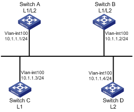
Networking and Configuration Requirements
As shown in Figure 1-14, Switch A, B, C and Switch D reside in IS-IS area 10 on a broadcast network (Ethernet). Switch A and Switch B are Level-1-2 switches, Switch C is a Level-1 switch, and Switch D is a Level-2 switch.
Change the DIS priority of Switch A to make it elected as the Level-1-2 DIS router.
Applicable Product Matrix
|
Product series |
Software version |
Hardware version |
|
S3610 series Etherent switches |
Release 5301 Release 5303 |
All versions |
|
S5510 series Etherent switches |
Release 5301 Release 5303 |
All versions |
|
S5500-EI series Etherent switches |
Release 2102 |
All versions |
|
S7500E series Etherent switches |
Release 6100 Release 6300 |
All versions |
Configuration Procedure
1) Configure an IP address for each interface (omitted)
2) Enable IS-IS
# Configure Switch A.
<SwitchA> system-view
[SwitchA] isis 1
[SwitchA-isis-1] network-entity 10.0000.0000.0001.00
[SwitchA-isis-1] quit
[SwitchA] interface vlan-interface 100
[SwitchA-Vlan-interface100] isis enable 1
[SwitchA-Vlan-interface100] quit
# Configure Switch B.
<SwitchB> system-view
[SwitchB] isis 1
[SwitchB-isis-1] network-entity 10.0000.0000.0002.00
[SwitchB-isis-1] quit
[SwitchB] interface vlan-interface 100
[SwitchB-Vlan-interface100] isis enable 1
[SwitchB-Vlan-interface100] quit
# Configure Switch C.
<SwitchC> system-view
[SwitchC] isis 1
[SwitchC-isis-1] network-entity 10.0000.0000.0003.00
[SwitchC-isis-1] is-level level-1
[SwitchC-isis-1] quit
[SwitchC] interface vlan-interface 100
[SwitchC-Vlan-interface100] isis enable 1
[SwitchC-Vlan-interface100] quit
# Configure Switch D.
<SwitchD> system-view
[SwitchD] isis 1
[SwitchD-isis-1] network-entity 10.0000.0000.0004.00
[SwitchD-isis-1] is-level level-2
[SwitchD-isis-1] quit
[SwitchD] interface vlan-interface 100
[SwitchD-Vlan-interface100] isis enable 1
[SwitchD-Vlan-interface100] quit
# Display information about IS-IS neighbors of Switch A.
[SwitchA] display isis peer
Peer information for ISIS(1)
----------------------------
System Id: 0000.0000.0002
Interface: Vlan-interface100 Circuit Id: 0000.0000.0003.01
State: Up HoldTime: 21s Type: L1(L1L2) PRI: 64
System Id: 0000.0000.0003
Interface: Vlan-interface100 Circuit Id: 0000.0000.0003.01
State: Up HoldTime: 27s Type: L1 PRI: 64
System Id: 0000.0000.0002
Interface: Vlan-interface100 Circuit Id: 0000.0000.0004.01
State: Up HoldTime: 28s Type: L2(L1L2) PRI: 64
System Id: 0000.0000.0004
Interface: Vlan-interface100 Circuit Id: 0000.0000.0004.01
State: Up HoldTime: 30s Type: L2 PRI: 64
# Display information about IS-IS interfaces of Switch A.
[SwitchA] display isis interface
Interface information for ISIS(1)
---------------------------------
Interface: Vlan-interface100
Id IPV4.State IPV6.State MTU Type DIS
001 Up Down 1497 L1/L2 No/No
# Display information about IS-IS interfaces of Switch C.
[SwitchC] display isis interface
Interface information for ISIS(1)
---------------------------------
Interface: Vlan-interface100
Id IPV4.State IPV6.State MTU Type DIS
001 Up Down 1497 L1/L2 Yes/No
# Display information about IS-IS interfaces of Switch D.
[SwitchD] display isis interface
Interface information for ISIS(1)
---------------------------------
Interface: Vlan-interface100
Id IPV4.State IPV6.State MTU Type DIS
001 Up Down 1497 L1/L2 No/Yes
![]()
By using the default DIS priority, Switch C is the Level-1 DIS, and Switch D is the Level-2 DIS. The pseudonodes of Level-1 and Level-2 are 0000.0000.0003.01 and 0000.0000.0004.01 respectively.
3) Configure the DIS priority of Switch A.
[SwitchA] interface vlan-interface 100
[SwitchA-Vlan-interface100] isis dis-priority 100
[SwitchA-Vlan-interface100] quit
# Display IS-IS neighbors of Switch A.
[SwitchA] display isis peer
Peer information for ISIS(1)
----------------------------
System Id: 0000.0000.0002
Interface: Vlan-interface100 Circuit Id: 0000.0000.0001.01
State: Up HoldTime: 21s Type: L1(L1L2) PRI: 64
System Id: 0000.0000.0003
Interface: Vlan-interface100 Circuit Id: 0000.0000.0001.01
State: Up HoldTime: 27s Type: L1 PRI: 64
System Id: 0000.0000.0002
Interface: Vlan-interface100 Circuit Id: 0000.0000.0001.01
State: Up HoldTime: 28s Type: L2(L1L2) PRI: 64
System Id: 0000.0000.0004
Interface: Vlan-interface100 Circuit Id: 0000.0000.0001.01
State: Up HoldTime: 30s Type: L2 PRI: 64
# # Display information about IS-IS interfaces of Switch A.
[SwitchA] display isis interface
Interface information for ISIS(1)
---------------------------------
Interface: Vlan-interface100
Id IPV4.State IPV6.State MTU Type DIS
001 Up Down 1497 L1/L2 Yes/Yes
![]()
After the DIS priority configuration, Switch A becomes the Level-1-2 DIS, and the pseudonode is 0000.0000.0001.01.
# Display information about IS-IS neighbors and interfaces of Switch C.
[SwitchC] display isis peer
Peer information for ISIS(1)
----------------------------
System Id: 0000.0000.0002
Interface: Vlan-interface100 Circuit Id: 0000.0000.0001.01
State: Up HoldTime: 25s Type: L1 PRI: 64
System Id: 0000.0000.0001
Interface: Vlan-interface100 Circuit Id: 0000.0000.0001.01
State: Up HoldTime: 7s Type: L1 PRI: 100
[SwitchC] display isis interface
Interface information for ISIS(1)
---------------------------------
Interface: Vlan-interface100
Id IPV4.State IPV6.State MTU Type DIS
001 Up Down 1497 L1/L2 No/No
# Display information about IS-IS neighbors and interfaces of Switch D.
[SwitchD] display isis peer
Peer information for ISIS(1)
----------------------------
System Id: 0000.0000.0001
Interface: Vlan-interface100 Circuit Id: 0000.0000.0001.01
State: Up HoldTime: 9s Type: L2 PRI: 100
System Id: 0000.0000.0002
Interface: Vlan-interface100 Circuit Id: 0000.0000.0001.01
State: Up HoldTime: 28s Type: L2 PRI: 64
[SwitchD] display isis interface
Interface information for ISIS(1)
---------------------------------
Interface: Vlan-interface100
Id IPV4.State IPV6.State MTU Type DIS
001 Up Down 1497 L1/L2 No/No
Complete Configuration
l Configure Switch A.
#
vlan 100
#
isis 1
network-entity 10.0000.0000.0001.00
#
interface Vlan-interface100
ip address 10.1.1.1 255.255.255.0
isis enable 1
isis dis-priority 100
#
l Configure Switch B.
#
vlan 100
#
isis 1
network-entity 10.0000.0000.0002.00
#
interface Vlan-interface100
ip address 10.1.1.2 255.255.255.0
isis enable 1
#
l Configure Switch C.
#
vlan 100
#
isis 1
is-level level-1
network-entity 10.0000.0000.0003.00
#
interface Vlan-interface100
ip address 10.1.1.3 255.255.255.0
isis enable 1
#
l Configure Switch D.
#
vlan 100
#
isis 1
is-level level-2
network-entity 10.0000.0000.0004.00
#
interface Vlan-interface100
ip address 10.1.1.4 255.255.255.0
isis enable 1
#
Configuration Guidelines
l On an IS-IS broadcast network, a router should be selected as the DIS at a specific level, Level-1 or Level-2. You can specify a DIS priority at a level for an interface. The bigger the interface’s priority value, the more likely it becomes the DIS.
l If multiple routers in the broadcast network have the same highest DIS priority, the router with the highest MAC address becomes the DIS. This rule applies even all routers’ DIS priority is 0.
Configuring IS-IS Route Redistribution
Network diagram
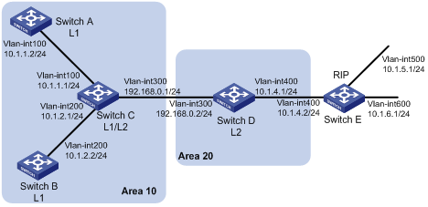
Networking and Configuration Requirements
Switch A, Switch B, Switch C and Switch D reside in the same AS. They use IS-IS to interconnect. Switch A and Switch B are Level-1 routers, Switch D is a Level-2 router, and Switch C is a Level-1-2 router.
It is required to redistribute RIP routes into IS-IS on Switch D.
Applicable Product Matrix
|
Product series |
Software version |
Hardware version |
|
S3610 Series Ethernet Switches |
Release 5301, Release 5303 |
All versions |
|
S5510 Series Ethernet Switches |
Release 5301, Release 5303 |
All versions |
|
S5500-EI Series Ethernet Switches |
Release 2102 |
All versions |
|
S7500E Series Ethernet Switches |
Release 6100, Release 6300 |
All versions |
Configuration Procedure
1) Configure IP addresses for interfaces (omitted)
2) Configure IS-IS basic functions
# Configure Switch A.
<SwitchA> system-view
[SwitchA] isis 1
[SwitchA-isis-1] is-level level-1
[SwitchA-isis-1] network-entity 10.0000.0000.0001.00
[SwitchA-isis-1] quit
[SwitchA] interface vlan-interface 100
[SwitchA-Vlan-interface100] isis enable 1
[SwitchA-Vlan-interface100] quit
# Configure Switch B.
<SwitchB> system-view
[SwitchB] isis 1
[SwitchB-isis-1] is-level level-1
[SwitchB-isis-1] network-entity 10.0000.0000.0002.00
[SwitchB-isis-1] quit
[SwitchB] interface vlan-interface 200
[SwitchB-Vlan-interface200] isis enable 1
[SwitchB-Vlan-interface200] quit
# Configure Switch C.
<SwitchC> system-view
[SwitchC] isis 1
[SwitchC-isis-1] network-entity 10.0000.0000.0003.00
[SwitchC-isis-1] quit
[SwitchC] interface vlan-interface 200
[SwitchC-Vlan-interface200] isis enable 1
[SwitchC-Vlan-interface200] quit
[SwitchC] interface vlan-interface 100
[SwitchC-Vlan-interface100] isis enable 1
[SwitchC-Vlan-interface100] quit
[SwitchC] interface vlan-interface 300
[SwitchC-Vlan-interface300] isis enable 1
[SwitchC-Vlan-interface300] quit
# Configure Switch D.
<SwitchD> system-view
[SwitchD] isis 1
[SwitchD-isis-1] is-level level-2
[SwitchD-isis-1] network-entity 20.0000.0000.0004.00
[SwitchD-isis-1] quit
[SwitchD] interface interface vlan-interface 300
[SwitchD-Vlan-interface300] isis enable 1
[SwitchD-Vlan-interface300] quit
# Display IS-IS routing information on each switch.
[SwitchA] display isis route
Route information for ISIS(1)
-----------------------------
ISIS(1) IPv4 Level-1 Forwarding Table
-------------------------------------
IPV4 Destination IntCost ExtCost ExitInterface NextHop Flags
--------------------------------------------------------------------------
10.1.1.0/24 10 NULL VLAN100 Direct D/L/-
10.1.2.0/24 20 NULL VLAN100 10.1.1.1 R/-/-
192.168.0.0/24 20 NULL VLAN100 10.1.1.1 R/-/-
0.0.0.0/0 10 NULL VLAN100 10.1.1.1 R/-/-
Flags: D-Direct, R-Added to RM, L-Advertised in LSPs, U-Up/Down Bit Set
[SwitchC] display isis route
Route information for ISIS(1)
-----------------------------
ISIS(1) IPv4 Level-1 Forwarding Table
-------------------------------------
IPV4 Destination IntCost ExtCost ExitInterface NextHop Flags
--------------------------------------------------------------------------
10.1.1.0/24 10 NULL VLAN100 Direct D/L/-
10.1.2.0/24 10 NULL VLAN200 Direct D/L/-
192.168.0.0/24 10 NULL VLAN300 Direct D/L/-
Flags: D-Direct, R-Added to RM, L-Advertised in LSPs, U-Up/Down Bit Set
ISIS(1) IPv4 Level-2 Forwarding Table
-------------------------------------
IPV4 Destination IntCost ExtCost ExitInterface NextHop Flags
--------------------------------------------------------------------------
10.1.1.0/24 10 NULL VLAN100 Direct D/L/-
10.1.2.0/24 10 NULL VLAN200 Direct D/L/-
192.168.0.0/24 10 NULL VLAN300 Direct D/L/-
Flags: D-Direct, R-Added to RM, L-Advertised in LSPs, U-Up/Down Bit Set
[SwitchD] display isis route
Route information for ISIS(1)
-----------------------------
ISIS(1) IPv4 Level-2 Forwarding Table
-------------------------------------
IPV4 Destination IntCost ExtCost ExitInterface NextHop Flags
--------------------------------------------------------------------------
192.168.0.0/24 10 NULL VLAN300 Direct D/L/-
10.1.1.0/24 20 NULL VLAN300 192.168.0.1 R/-/-
10.1.2.0/24 20 NULL VLAN300 192.168.0.1 R/-/-
Flags: D-Direct, R-Added to RM, L-Advertised in LSPs, U-Up/Down Bit Set
3) Configure RIPv2 on Switch D and Switch E, and configure route redistribution from RIP to IS-IS on Switch D.
# Configure RIPv2 on Switch D.
[SwitchD] rip 1
[SwitchD-rip-1] network 10.0.0.0
[SwitchD-rip-1] version 2
[SwitchD-rip-1] undo summary
# Configure RIPv2 on Switch E.
[SwitchE] rip 1
[SwitchE-rip-1] network 10.0.0.0
[SwitchE-rip-1] version 2
[SwitchE-rip-1] undo summary
# Configure route redistribution from RIP to IS-IS on Switch D.
[SwitchD-rip-1] quit
[SwitchD] isis 1
[SwitchD–isis] import-route rip level-2
# Display IS-IS routing information on Switch C.
[SwitchC] display isis route
Route information for ISIS(1)
-----------------------------
ISIS(1) IPv4 Level-1 Forwarding Table
-------------------------------------
IPV4 Destination IntCost ExtCost ExitInterface NextHop Flags
--------------------------------------------------------------------------
10.1.1.0/24 10 NULL VLAN100 Direct D/L/-
10.1.2.0/24 10 NULL VLAN200 Direct D/L/-
192.168.0.0/24 10 NULL VLAN300 Direct D/L/-
Flags: D-Direct, R-Added to RM, L-Advertised in LSPs, U-Up/Down Bit Set
ISIS(1) IPv4 Level-2 Forwarding Table
-------------------------------------
IPV4 Destination IntCost ExtCost ExitInterface NextHop Flags
--------------------------------------------------------------------------
10.1.1.0/24 10 NULL VLAN100 Direct D/L/-
10.1.2.0/24 10 NULL VLAN200 Direct D/L/-
192.168.0.0/24 10 NULL VLAN300 Direct D/L/-
10.1.4.0/24 10 NULL VLAN300 192.168.0.2 R/L/-
10.1.5.0/24 20 NULL VLAN300 192.168.0.2 R/L/-
10.1.6.0/24 20 NULL VLAN300 192.168.0.2 R/L/-
Flags: D-Direct, R-Added to RM, L-Advertised in LSPs, U-Up/Down Bit Set
Complete Configuration
l Configure Switch A
#
vlan 100
#
isis 1
is-level level-1
network-entity 10.0000.0000.0001.00
#
interface Vlan-interface100
ip address 10.1.1.2 255.255.255.0
isis enable 1
#
l Configure Switch B
#
vlan 200
#
isis 1
is-level level-1
network-entity 10.0000.0000.0002.00
#
interface Vlan-interface200
ip address 10.1.2.2 255.255.255.0
isis enable 1
#
l Configure Switch C
#
vlan 100
#
vlan 200
#
vlan 300
#
isis 1
is-level level-1
network-entity 10.0000.0000.0003.00
#
interface Vlan-interface100
ip address 10.1.1.1 255.255.255.0
isis enable 1
#
interface Vlan-interface200
ip address 10.1.2.2 255.255.255.0
isis enable 1
#
interface Vlan-interface300
ip address 192.168.0.1 255.255.255.0
isis enable 1
#
l Configure Switch D
#
vlan 300
#
vlan 400
#
isis 1
is-level level-2
network-entity 20.0000.0000.0004.00
import-route rip 1
#
interface Vlan-interface300
ip address 192.168.0.2 255.255.255.0
isis enable 1
#
rip 1
undo summary
version 2
network 10.0.0.0
#
l Configure Switch E
#
vlan 400
#
vlan 500
#
vlan 600
#
interface Vlan-interface400
ip address 10.1.4.2 255.255.255.0
#
interface Vlan-interface500
ip address 10.1.5.1 255.255.255.0
#
interface Vlan-interface600
ip address 10.1.6.1 255.255.255.0
#
rip 1
undo summary
version 2
network 10.0.0.0
#
Configuration Guidelines
None
Configuring IS-IS GR
After an IS-IS GR Restarter restarts IS-IS, it needs to complete the following two tasks to synchronize the LSDB with its neighbors.
l To obtain effective IS-IS neighbor information without changing adjacencies.
l To obtain the LSDB contents.
After the restart, the GR Restarter will send an OSPF GR signal to its neighbors to keep the adjacencies. After receiving the responses from neighbors, the GR Restarter can restore the neighbor table.
After reestablishing neighbor relationships, the GR Restarter will synchronize the LSDB and exchange routing information with all adjacent GR capable neighbors. After that, the GR Restarter will update its own routing table and forwarding table based on the new routing information and remove the stale routes. In this way, the IS-IS routing convergence is complete.
Network Diagram
Figure 1-16 Network diagram for IS-IS GR configuration
Figure 1-17 Network diagram for BGP basic configuration
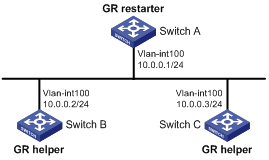
Networking and Configuration Requirements
Switch A, Switch B, and Switch C are interconnected to each other in the same IS-IS routing domain. These switches are reachable to one another through IS-IS, as illustrated in Figure 1-16.
Applicable Product Matrix
|
Product series |
Software version |
Hardware version |
|
S3610 Series Ethernet Switches |
Release 5301 Release 5303 |
All versions |
|
S5510 Series Ethernet Switches |
Release 5301 Release 5303 |
All versions |
|
S5500-EI Series Ethernet Switches |
Release 2102 |
All versions |
Configuration Procedure
1) Configure IP addresses of the interfaces on each switch and configure IS-IS.
Configure the IP address and subnet mask of each interface. The configuration procedure is omitted.
Configure IS-IS on the switches, ensuring that Switch A, Switch B and Switch C can communicate with each other at layer 3 and dynamic route update can be implemented among them with IS-IS. The configuration procedure is omitted here.
2) Configure IS-IS Graceful Restart.
# Enable IS-IS Graceful Restart on Switch A and configure the Graceful Restart Interval.
<SwitchA> system-view
[SwitchA] isis 1
[SwitchA-isis-1] graceful-restart
[SwitchA-isis-1] graceful-restart interval 150
[SwitchA-isis-1] return
Configurations for Switch B and Switch C are similar and therefore are omitted here.
3) Verify the configuration.
After Switch A establishes adjacencies with Switch B and Switch C, they begin to exchange routing information. Restart IS-IS on Switch A, which enters into the restart state and sends connection requests to its neighbors through the Graceful Restart mechanism to synchronize the LSDB. Using the display isis graceful-restart status command can display the IS-IS GR status on Switch A.
# Restart Switch A.
<SwitchA> reset isis all 1
Warning : Reset ISIS process? [Y/N]:y
# Check the Graceful Restart status of IS-IS on Switch A.
<SwitchA> display isis graceful-restart status
Restart information for ISIS(1)
-------------------------------
IS-IS(1) Level-1 Restart Status
Restart Interval: 150
SA Bit Supported
Total Number of Interfaces = 1
Restart Status: RESTARTING
T3 Timer Status:
Remaining Time: 65535
T2 Timer Status:
Remaining Time: 59
Interface Vlan1
T1 Timer Status:
Remaining Time: 1
RA Not Received
Complete CSNP Not Received
Number of T1 Pre Expiry: 0
IS-IS(1) Level-2 Restart Status
Restart Interval: 150
SA Bit Supported
Total Number of Interfaces = 1
Restart Status: RESTARTING
T3 Timer Status:
Remaining Time: 65535
T2 Timer Status:
Remaining Time: 59
Interface Vlan1
T1 Timer Status:
Remaining Time: 1
RA Not Received
Complete CSNP Not Received
Number of T1 Pre Expiry: 0
Complete Configuration
l Configure Switch A
#
vlan 100
#
isis 1
graceful-restart
graceful-restart interval 150
network-entity 10.0000.0000.0003.00
#
interface Vlan-interface100
ip address 10.0.0.1 255.255.255.0
isis enable 1
#
l Configure Switch B
#
vlan 100
#
isis 1
graceful-restart
graceful-restart interval 150
is-level level-1
network-entity 10.0000.0000.0001.00
#
interface Vlan-interface100
ip address 10.0.0.2 255.255.255.0
isis enable 1
#
l Configure Switch C
#
vlan 100
#
isis 1
graceful-restart
graceful-restart interval 150
is-level level-1
network-entity 10.0000.0000.0002.00
#
interface Vlan-interface100
ip address 10.0.0.3 255.255.255.0
isis enable 1
#
Configuration Guidelines
None
Configuring IS-IS Authentication
Network Diagram
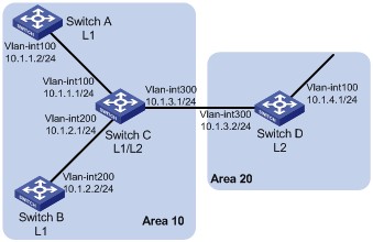
Networking and Configuration Requirements
Switch A, Switch B, Switch C and Switch D reside in the same IS-IS routing domain.
Switch A, Switch B, and Switch C belong to Area 10, and Switch D belongs to Area 20.
Configure neighbor relationship authentication between neighbors. Configure area authentication in Area 10 to prevent untrusted routes from entering into the area. Configure routing domain authentication on Switch C and Switch D to prevent untrusted routes from entering the routing domain.
Applicable Product Matrix
|
Product series |
Software version |
Hardware version |
|
S3610 Series Ethernet Switches |
Release 5301, Release 5303 |
All versions |
|
S5510 Series Ethernet Switches |
Release 5301, Release 5303 |
All versions |
|
S5500-EI Series Ethernet Switches |
Release 2102 |
All versions |
|
S7500E Series Ethernet Switches |
Release 6100, Release 6300 |
All versions |
Configuration Procedure
1) Configure IP addresses for interfaces (Omitted).
2) Configure IS-IS basic functions.
# Configure Switch A.
<SwitchA> system-view
[SwitchA] isis 1
[SwitchA-isis-1] network-entity 10.0000.0000.0001.00
[SwitchA-isis-1] quit
[SwitchA] interface vlan-interface 100
[SwitchA-Vlan-interface100] isis enable 1
[SwitchA-Vlan-interface100] quit
# Configure Switch B.
<SwitchB> system-view
[SwitchB] isis 1
[SwitchB-isis-1] network-entity 10.0000.0000.0002.00
[SwitchB-isis-1] quit
[SwitchB] interface vlan-interface 200
[SwitchB-Vlan-interface200] isis enable 1
[RouterB--Vlan-interface200] quit
# Configure Switch C.
<SwitchC> system-view
[SwitchC] isis 1
[SwitchC-isis-1] network-entity 10.0000.0000.0003.00
[SwitchC-isis-1] quit
[SwitchC] interface vlan-interface 200
[SwitchC-Vlan-interface200] isis enable 1
[SwitchC-Vlan-interface200] quit
[SwitchC] interface vlan-interface 300
[SwitchC-Vlan-interface300] isis enable 1
[SwitchC-Vlan-interface300] quit
[SwitchC] interface vlan-interface 300
[SwitchC-Vlan-interface300] isis enable 1
[SwitchC-Vlan-interface300] quit
# Configure Switch D.
<SwitchD> system-view
[SwitchD] isis 1
[SwitchD-isis-1] network-entity 20.0000.0000.0001.00
[SwitchD-isis-1] quit
[SwitchD] interface vlan-interface 300
[SwitchD-Vlan-interface300] isis enable 1
[SwitchD-Vlan-interface300] quit
3) Configure neighbor relationship authentication between neighbors.
# Specify the MD5 authentication mode and password eRq on VLAN-interface 100 of Switch A and on VLAN-interface 100 of Switch C.
[SwitchA] interface vlan-interface 100
[SwitchA-Vlan-interface100] isis authentication-mode md5 eRg
[SwitchA-Vlan-interface100] quit
[SwitchC] interface vlan-interface 100
[SwitchC-Vlan-interface100] isis authentication-mode md5 eRg
[SwitchC-Vlan-interface100] quit
# Specify the MD5 authentication mode and password t5Hr on VLAN-interface 200 of Switch B and on VLAN-interface 200 of Switch C.
[SwitchB] interface vlan-interface 200
[SwitchB-Vlan-interface200] isis authentication-mode md5 t5Hr
[SwitchB-Vlan-interface200] quit
[SwitchC] interface vlan-interface 200
[SwitchC-Vlan-interface200] isis authentication-mode md5 t5Hr
[SwitchC-Vlan-interface200] quit
# Specify the MD5 authentication mode and password hSec on VLAN-interface 300 of Switch D and on VLAN-interface 300 of Switch C.
[SwitchC] interface vlan-interface 300
[SwitchC-Vlan-interface300] isis authentication-mode md5 hSec
[SwitchC-Vlan-interface300] quit
[SwitchD] interface vlan-interface 300
[SwitchD-Vlan-interface300] isis authentication-mode md5 hSec
[SwitchD-Vlan-interface300] quit
4) Configure area authentication. Specify the MD5 authentication mode and password 10Sec on Switch A, Switch B and Switch C.
[SwitchA] isis 1
[SwitchA-isis-1] area-authentication-mode md5 10Sec
[SwitchA-isis-1] quit
[SwitchB] isis 1
[SwitchB-isis-1] area-authentication-mode md5 10Sec
[SwitchB-isis-1] quit
[SwitchC] isis 1
[SwitchC-isis-1] area-authentication-mode md5 10Sec
[SwitchC-isis-1] quit
5) Configure routing domain authentication. Specify the MD5 authentication mode and password 1020Sec on Switch C and Switch D.
[SwitchC] isis 1
[SwitchC-isis-1] domain-authentication-mode md5 1020Sec
[SwitchC-isis-1] quit
[SwitchD] isis 1
[SwitchD-isis-1] domain-authentication-mode md5 1020Sec
Complete Configuration
l Configure Switch A.
#
vlan 100
#
isis 1
network-entity 10.0000.0000.0001.00
area-authentication-mode md5 4_"NF,<I(R/Q=^Q`MAF4<1!!
#
interface Vlan-interface100
ip address 10.1.1.2 255.255.255.0
isis enable 1
isis authentication-mode md5 #G&R_%_'^C[Q=^Q`MAF4<1!! level-1
isis authentication-mode md5 #G&R_%_'^C[Q=^Q`MAF4<1!! level-2
#
l Configure Switch B.
#
vlan 200
#
isis 1
network-entity 10.0000.0000.0002.00
area-authentication-mode md5 4_"NF,<I(R/Q=^Q`MAF4<1!!
#
interface Vlan-interface200
ip address 10.1.2.2 255.255.255.0
isis enable 1
isis authentication-mode md5 BG#5Z'a!THWQ=^Q`MAF4<1!! level-1
isis authentication-mode md5 BG#5Z'a!THWQ=^Q`MAF4<1!! level-2
#
l Configure Switch C.
#
vlan 100
#
vlan 200
#
vlan 300
#
isis 1
network-entity 10.0000.0000.0003.00
area-authentication-mode md5 4_"NF,<I(R/Q=^Q`MAF4<1!!
domain-authentication-mode md5 4@>KGW#KZ!_Q=^Q`MAF4<1!!
#
interface Vlan-interface100
ip address 10.1.1.1 255.255.255.0
isis enable 1
isis authentication-mode md5 #G&R_%_'^C[Q=^Q`MAF4<1!! level-1
isis authentication-mode md5 #G&R_%_'^C[Q=^Q`MAF4<1!! level-2
#
interface Vlan-interface200
ip address 10.1.2.1 255.255.255.0
isis enable 1
isis authentication-mode md5 BG#5Z'a!THWQ=^Q`MAF4<1!! level-1
isis authentication-mode md5 BG#5Z'a!THWQ=^Q`MAF4<1!! level-2
#
interface Vlan-interface300
ip address 10.1.3.1 255.255.255.0
isis enable 1
isis authentication-mode md5 WBG1G<<>#5[Q=^Q`MAF4<1!! level-1
isis authentication-mode md5 WBG1G<<>#5[Q=^Q`MAF4<1!! level-2
#
l Configure Switch C.
#
vlan 100
#
vlan 300
#
isis 1
network-entity 20.0000.0000.0001.00
domain-authentication-mode md5 4@>KGW#KZ!_Q=^Q`MAF4<1!!
#
interface Vlan-interface100
ip address 10.1.4.1 255.255.255.0
#
interface Vlan-interface300
ip address 10.1.3.2 255.255.255.0
isis enable 1
isis authentication-mode md5 WBG1G<<>#5[Q=^Q`MAF4<1!! level-1
isis authentication-mode md5 WBG1G<<>#5[Q=^Q`MAF4<1!! level-2
#
Configuration Guidelines
None
Configuring BGP Basic Functions
An autonomous system (AS) refers to a group of routers that share the same route policy and work under the same technical administration.
The Border Gateway Protocol (BGP) is a dynamic inter-AS route discovery protocol.
Three early versions of BGP are BGP-1 (RFC1105), BGP-2 (RFC1163) and BGP-3 (RFC1267). The current version in use is BGP-4 (RFC1771). BGP-4 is rapidly becoming the defacto Internet exterior routing protocol standard and is commonly used between ISPs.
The characteristics of BGP are as follows:
l Focusing on the control of route propagation and the selection of optimal routes rather than the discovery and calculation of routes, which makes BGP, an exterior routing protocol different from interior routing protocols such as OSPF and RIP
l Using TCP as its transport layer protocol to enhance reliability
l Supporting CIDR
l Substantially reducing bandwidth occupation by advertising updating routes only and applicable to advertising a great amount of routing information on the Internet
l Eliminating route loops completely by adding AS path information to BGP routes
l Providing abundant routing policies to implement flexible route filtering and selection
l Easy to extend, satisfying new network developments
Network Diagram
Figure 1-18 Network diagram for BGP and IGP Route Synchronization configuration
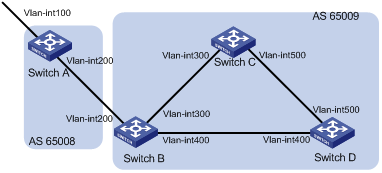
|
Interface |
IP address |
Device |
Interface |
IP address |
|
|
Switch A |
Vlan-int100 |
8.1.1.1/8 |
Switch D |
Vlan-int400 |
9.1.1.2/24 |
|
|
Vlan-int200 |
200.1.1.2/24 |
|
Vlan-int500 |
9.1.2.2/24 |
|
Switch B |
Vlan-int400 |
9.1.1.1/24 |
Switch C |
Vlan-int500 |
9.1.2.1/24 |
|
|
Vlan-int200 |
200.1.1.1/24 |
|
Vlan-int300 |
9.1.3.2/24 |
|
|
Vlan-int300 |
9.1.3.1/24 |
|
|
|
Networking and Configuration Requirements
In the following figure are all BGP switches. Between Switch A and Switch B is an EBGP connection. IBGP speakers Switch B, Switch C and Switch D are fully meshed.
Applicable Product Matrix
|
Product series |
Software version |
Hardware version |
|
S3610 Series Ethernet Switches |
Release 5301 Release 5303 |
All versions |
|
S5510 Series Ethernet Switches |
Release 5301 Release 5303 |
All versions |
|
S5500-EI Series Ethernet Switches |
Release 2102 |
All versions |
|
S7500E Series Ethernet Switches |
Release 6100 Release 6300 |
All versions |
Configuration Procedure
1) Configure IP addresses for interfaces (omitted)
2) Configure IBGP connections
# Configure Switch B. Enable BGP on it, and assign it router ID 2.2.2.2.
<SwitchB> system-view
[SwitchB] bgp 65009
[SwitchB-bgp] router-id 2.2.2.2
[SwitchB-bgp] peer 9.1.1.2 as-number 65009
[SwitchB-bgp] peer 9.1.3.2 as-number 65009
[SwitchB-bgp] quit
# Configure Switch C. Enable BGP on it, and assign it router ID 3.3.3.3.
<SwitchC> system-view
[SwitchC] bgp 65009
[SwitchC-bgp] router-id 3.3.3.3
[SwitchC-bgp] peer 9.1.3.1 as-number 65009
[SwitchC-bgp] peer 9.1.2.2 as-number 65009
[SwitchC-bgp] quit
# Configure Switch D. Enable BGP on it, and assign it router ID 4.4.4.4.
<SwitchD> system-view
[SwitchD] bgp 65009
[SwitchD-bgp] router-id 4.4.4.4
[SwitchD-bgp] peer 9.1.1.1 as-number 65009
[SwitchD-bgp] peer 9.1.2.1 as-number 65009
[SwitchD-bgp] quit
3) Configure the EBGP connection
# Configure Switch A. Enable BGP on it, and assign it router ID 1.1.1.1.
<SwitchA> system-view
[SwitchA] bgp 65008
[SwitchA-bgp] router-id 1.1.1.1
[SwitchA-bgp] peer 200.1.1.1 as-number 65009
# Inject network 8.0.0.0/8 to the BGP routing table.
[SwitchA-bgp] network 8.0.0.0
[SwitchA-bgp] quit
# Configure Switch B.
[SwitchB] bgp 65009
[SwitchB-bgp] peer 200.1.1.2 as-number 65008
[SwitchB-bgp] quit
# Display BGP peer information on Switch B.
[SwitchB] display bgp peer
BGP local router ID : 2.2.2.2
Local AS number : 65009
Total number of peers : 3 Peers in established state : 3
Peer V AS MsgRcvd MsgSent OutQ PrefRcv Up/Down State
9.1.1.2 4 65009 56 56 0 0 00:40:54 Established
9.1.3.2 4 65009 49 62 0 0 00:44:58 Established
200.1.1.2 4 65008 49 65 0 1 00:44:03 Established
You can find Switch B has established BGP connections to other switches.
# Display BGP routing table information on Switch A.
[SwitchA] display bgp routing-table
Total Number of Routes: 1
BGP Local router ID is 1.1.1.1
Status codes: * - valid, > - best, d - damped,
h - history, i - internal, s - suppressed, S - Stale
Origin : i - IGP, e - EGP, ? - incomplete
Network NextHop MED LocPrf PrefVal Path/Ogn
*> 8.0.0.0 0.0.0.0 0 0 i
# Display BGP routing table information on Switch B.
[SwitchB] display bgp routing-table
Total Number of Routes: 1
BGP Local router ID is 2.2.2.2
Status codes: * - valid, > - best, d - damped,
h - history, i - internal, s - suppressed, S - Stale
Origin : i - IGP, e - EGP, ? - incomplete
Network NextHop MED LocPrf PrefVal Path/Ogn
*> 8.0.0.0 200.1.1.2 0 0 65008i
# Display the BGP routing table on Switch C.
[SwitchC] display bgp routing-table
Total Number of Routes: 1
BGP Local router ID is 3.3.3.3
Status codes: * - valid, > - best, d - damped,
h - history, i - internal, s - suppressed, S - Stale
Origin : i - IGP, e - EGP, ? - incomplete
Network NextHop MED LocPrf PrefVal Path/Ogn
i 8.0.0.0 200.1.1.2 0 100 0 65008i
![]()
From the above outputs, you can find Switch A has learned no route to AS65009, and Switch C has learned network 8.0.0.0 but the next hop 200.1.1.2 is unreachable, so the route is invalid.
4) Redistribute direct routes
# Configure Switch B.
[SwitchB] bgp 65009
[SwitchB-bgp] import-route direct
# Display BGP routing table information on Switch A.
[SwitchA] display bgp routing-table
Total Number of Routes: 4
BGP Local router ID is 1.1.1.1
Status codes: * - valid, > - best, d - damped,
h - history, i - internal, s - suppressed, S - Stale
Origin : i - IGP, e - EGP, ? - incomplete
Network NextHop MED LocPrf PrefVal Path/Ogn
*> 8.0.0.0 0.0.0.0 0 0 i
*> 9.1.1.0/24 200.1.1.1 0 0 65009?
*> 9.1.3.0/24 200.1.1.1 0 0 65009?
* 200.1.1.0 200.1.1.1 0 0 65009?
# Display BGP routing table information on Switch C.
[SwitchC] display bgp routing-table
Total Number of Routes: 4
BGP Local router ID is 3.3.3.3
Status codes: * - valid, > - best, d - damped,
h - history, i - internal, s - suppressed, S - Stale
Origin : i - IGP, e - EGP, ? - incomplete
Network NextHop MED LocPrf PrefVal Path/Ogn
*>i 8.0.0.0 200.1.1.2 0 100 0 65008i
*>i 9.1.1.0/24 9.1.3.1 0 100 0 ?
* i 9.1.3.0/24 9.1.3.1 0 100 0 ?
*>i 200.1.1.0 9.1.3.1 0 100 0 ?
You can find the route 8.0.0.0 becomes valid with the next hop being Switch A.
# Ping 8.1.1.1 on Switch C.
[SwitchC] ping 8.1.1.1
PING 8.1.1.1: 56 data bytes, press CTRL_C to break
Reply from 8.1.1.1: bytes=56 Sequence=1 ttl=254 time=31 ms
Reply from 8.1.1.1: bytes=56 Sequence=2 ttl=254 time=47 ms
Reply from 8.1.1.1: bytes=56 Sequence=3 ttl=254 time=31 ms
Reply from 8.1.1.1: bytes=56 Sequence=4 ttl=254 time=16 ms
Reply from 8.1.1.1: bytes=56 Sequence=5 ttl=254 time=31 ms
--- 8.1.1.1 ping statistics ---
5 packet(s) transmitted
5 packet(s) received
0.00% packet loss
round-trip min/avg/max = 16/31/47 ms
Complete Configuration
l Configure Switch A
#
vlan 100
#
vlan 200
#
interface Vlan-interface100
ip address 8.1.1.1 255.0.0.0
#
interface Vlan-interface200
ip address 200.1.1.2 255.255.255.0
#
bgp 65008
router-id 1.1.1.1
network 8.0.0.0
undo synchronization
peer 200.1.1.1 as-number 65009
#
l Configure Switch B
#
vlan 200
#
vlan 300
#
vlan 400
#
interface Vlan-interface200
ip address 200.1.1.1 255.255.255.0
#
interface Vlan-interface300
ip address 9.1.3.1 255.255.255.0
#
interface Vlan-interface400
ip address 9.1.1.1 255.255.255.0
#
bgp 65009
router-id 2.2.2.2
import-route direct
undo synchronization
peer 9.1.1.2 as-number 65009
peer 200.1.1.2 as-number 65008
peer 9.1.3.2 as-number 65009
#
l Configure Switch C
#
vlan 300
#
vlan 500
#
interface Vlan-interface300
ip address 9.1.3.2 255.255.255.0
#
interface Vlan-interface500
ip address 9.1.2.1 255.255.255.0
#
bgp 65009
router-id 3.3.3.3
undo synchronization
peer 9.1.2.2 as-number 65009
peer 9.1.3.1 as-number 65009
#
l Configure Switch D
#
vlan 400
#
vlan 500
#
interface Vlan-interface400
ip address 9.1.1.2 255.255.255.0
#
interface Vlan-interface500
ip address 9.1.2.2 255.255.255.0
#
bgp 65009
router-id 4.4.4.4
undo synchronization
peer 9.1.1.1 as-number 65009
peer 9.1.2.1 as-number 65009
#
Configuration Guidelines
l It is required to specify for a BGP router a router ID, a 32-bit unsigned integer and the unique identifier of the router in the AS.
l If an option is configured both for a peer and for the peer group, the latest configuration takes effect.
l Since BGP employs TCP, you need to specify IP addresses of peers, which may not be neighboring routers. Using logical links can also establish BGP peer relationships. In general, IP addresses of loopback interfaces are used to improve stability of BGP connections.
l You can specify a router ID manually. If not, the system selects an IP address as the router ID. The selection sequence is the highest IP address among loopback interface addresses; if not available, then the highest IP address of interfaces. It is recommended to specify a loopback interface address as the router ID to enhance network reliability. Only when the interface with the selected Router ID or the manual Router ID is deleted will the system select another ID for the router.
l To establish multiple BGP connections between two routers, you need to specify on the local router the source interfaces for establishing TCP connections to the peers on the peering BGP router respectively; otherwise, the local BGP router may fail to establish TCP connections to the peers when using the outbound interfaces of the best routes as the source interfaces.
l In general, direct physical links should be available between EBGP peers. If not, you can use the peer ebgp-max-hop command to establish a TCP connection over multiple hops between two peers. You need not use this command for directly connected EBGP peers, which employ loopback interfaces for peer relationship establishment.
l You need not specify the AS number when creating an IBGP peer group.
l If there are peers in a peer group, you can neither change the AS number of the group nor use the undo command to remove the AS number
l You need specify the AS number for each peer in a mixed EBGP peer group respectively.
Configuring BGP and IGP Route Synchronization
BGP can advertise the routing information of the local AS to peering ASs, but it redistributes routing information from IGP into BGP rather than self-finding. During route redistribution, BGP can filter routing information from specific routing protocols.
Network Diagram
Figure 1-19 Network diagram for BGP path selection configuration
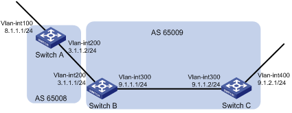
Networking and Configuration Requirements
OSPF is used as the IGP protocol in AS65009, where Switch C is a non-BGP switch. Between Switch A and Switch B is an EBGP connection.
Applicable Product Matrix
|
Product series |
Software version |
Hardware version |
|
S3610 series Etherent switches |
Release 5301 Release 5303 |
All versions |
|
S5510 series Etherent switches |
Release 5301 Release 5303 |
All versions |
|
S5500-EI series Etherent switches |
Release 2102 |
All versions |
|
S7500E series Etherent switches |
Release 6100 Release 6300 |
All versions |
Configuration Procedure
1) Configure IP addresses for interfaces (omitted)
2) Configure OSPF (omitted)
3) Configure the EBGP connection
# Configure Switch A. Enable BGP on it, and assign it router ID 1.1.1.1.
<SwitchA> system-view
[SwitchA] bgp 65008
[SwitchA-bgp] router-id 1.1.1.1
[SwitchA-bgp] peer 3.1.1.1 as-number 65009
# Inject network 8.1.1.0/24 to the BGP routing table.
[SwitchA-bgp] network 8.1.1.0 24
[SwitchA-bgp] quit
# Configure Switch B. Enable BGP on it, and assign it router ID 2.2.2.2.
<SwitchB> system-view
[SwitchB] bgp 65009
[SwitchA-bgp] router-id 2.2.2.2
[SwitchB-bgp] peer 3.1.1.2 as-number 65008
[SwitchB-bgp] quit
Configure BGP and IGP synchronization
# Configure BGP to redistribute routes from OSPF on Switch B.
[SwitchB] bgp 65009
[SwitchB-bgp] import-route ospf 1
[SwitchB-bgp] quit
# Display routing table information on Switch A.
[SwitchA] display bgp routing-table
Total Number of Routes: 3
BGP Local router ID is 1.1.1.1
Status codes: * - valid, > - best, d - damped,
h - history, i - internal, s - suppressed, S - Stale
Origin : i - IGP, e - EGP, ? - incomplete
Network NextHop MED LocPrf PrefVal Path/Ogn
*> 8.1.1.0/24 0.0.0.0 0 0 i
*> 9.1.1.0/24 3.1.1.1 0 0 65009?
*> 9.1.2.0/24 3.1.1.1 2 0 65009?
# Configure OSPF to redistribute routes from BGP on Switch B.
[SwitchB] ospf
[SwitchB-ospf-1] import-route bgp
[SwitchB-ospf-1] quit
# Display routing table information on Switch C.
<SwitchC> display ip routing-table
Routing Tables: Public
Destinations : 7 Routes : 7
Destination/Mask Proto Pre Cost NextHop Interface
8.1.1.0/24 O_ASE 150 1 9.1.1.1 Vlan300
9.1.1.0/24 Direct 0 0 9.1.1.2 Vlan300
9.1.1.2/32 Direct 0 0 127.0.0.1 InLoop0
9.1.2.0/24 Direct 0 0 9.1.2.1 Vlan400
9.1.2.1/32 Direct 0 0 127.0.0.1 InLoop0
127.0.0.0/8 Direct 0 0 127.0.0.1 InLoop0
127.0.0.1/32 Direct 0 0 127.0.0.1 InLoop0
4) Configure route automatic summarization
# Configure route automatic summarization on Switch B.
[SwitchB] bgp 65009
[SwitchB-bgp] summary automatic
# Display BGP routing table information on Switch A.
[SwitchA] display bgp routing-table
Total Number of Routes: 2
BGP Local router ID is 1.1.1.1
Status codes: * - valid, > - best, d - damped,
h - history, i - internal, s - suppressed, S - Stale
Origin : i - IGP, e - EGP, ? - incomplete
Network NextHop MED LocPrf PrefVal Path/Ogn
*> 8.1.1.0/24 0.0.0.0 0 0 i
*> 9.0.0.0 3.1.1.1 0 65009?
# Use ping for verification.
[SwitchA] ping -a 8.1.1.1 9.1.2.1
PING 9.1.2.1: 56 data bytes, press CTRL_C to break
Reply from 9.1.2.1: bytes=56 Sequence=1 ttl=254 time=15 ms
Reply from 9.1.2.1: bytes=56 Sequence=2 ttl=254 time=31 ms
Reply from 9.1.2.1: bytes=56 Sequence=3 ttl=254 time=47 ms
Reply from 9.1.2.1: bytes=56 Sequence=4 ttl=254 time=46 ms
Reply from 9.1.2.1: bytes=56 Sequence=5 ttl=254 time=47 ms
--- 9.1.2.1 ping statistics ---
5 packet(s) transmitted
5 packet(s) received
0.00% packet loss
round-trip min/avg/max = 15/37/47 ms
Complete Configuration
l Configure Switch A
#
vlan 100
#
vlan 200
#
interface Vlan-interface100
ip address 8.1.1.1 255.255.255.0
#
interface Vlan-interface200
ip address 3.1.1.2 255.255.255.0
#
bgp 65008
router-id 1.1.1.1
network 8.1.1.0 255.255.255.0
undo synchronization
peer 3.1.1.1 as-number 65009
#
l Configure Switch B
#
vlan 200
#
vlan 300
#
interface Vlan-interface200
ip address 3.1.1.1 255.255.255.0
#
interface Vlan-interface300
ip address 9.1.1.1 255.255.255.0
#
bgp 65009
router-id 2.2.2.2
summary automatic
import-route ospf 1
undo synchronization
peer 3.1.1.2 as-number 65008
#
ospf 1
import-route bgp
area 0.0.0.0
network 9.1.1.0 0.0.0.255
#
l Configure Switch C
#
vlan 300
#
vlan 400
#
interface Vlan-interface300
ip address 9.1.1.2 255.255.255.0
#
interface Vlan-interface400
ip address 9.1.2.1 255.255.255.0
#
ospf 1
area 0.0.0.0
network 9.1.1.0 0.0.0.255
network 9.1.2.0 0.0.0.255
#
Configuration Guidelines
l The ORIGIN attribute of routes redistributed using the import-route command is Incomplete.
l The ORIGIN attribute of networks advertised into the BGP routing table with the network command is IGP. These networks must exist in the local IP routing table, and using a routing policy makes routes control more flexible.
Configuring BGP Load Balancing
Currently, the switch supports BGP load balancing based on route recursion, namely if reliable routes are load balanced (suppose three next hop addresses), BGP generates the same number of next hops to forward packets. Note that BGP load balancing based on route recursion is always enabled on the switch rather than configured using commands.
BGP differs from IGP in the implementation of load balancing in the following:
l IGP routing protocols such as RIP, OSPF compute metrics of routes, and then implement load balancing on routes with the same metric and to the same destination. The route selection criterion is metric.
l BGP has no route computation algorithm, so it cannot implement load balancing according to metrics of routes. However, BGP has abundant route selection rules, through which, it selects available routes for load balancing and adds load balancing to route selection rules.
The MED attribute is exchanged between two neighboring ASs, each of which does not advertise the attribute to any other AS.
Similar with metrics used by IGP, MED is used to determine the best route for traffic going into an AS. When a BGP router obtains multiple routes to the same destination but with different next hops, it considers the route with the smallest MED value the best route if other conditions are the same.
Network Diagram
Figure 1-20 Network diagram for BGP community configuration
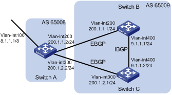
Networking and Configuration Requirements
All the switches run BGP. Switch A resides in AS 65008, Switch B and Switch C in AS 65009. Between Switch A and Switch B, Switch A and Switch C are eBGP connections, and between Switch B and Switch C is an iBGP connection. Two routes are configured on Switch A for load balancing.
Applicable Product Matrix
|
Product series |
Software version |
Hardware version |
|
S3610 series Etherent switches |
Release 5301 Release 5303 |
All versions |
|
S5510 series Etherent switches |
Release 5301 Release 5303 |
All versions |
|
S5500-EI series Etherent switches |
Release 2102 |
All versions |
|
S7500 series Etherent switches |
Release 6100 Release 6300 |
All versions |
Configuration Procedure
1) Configure IP addresses for interfaces (omitted)
2) Configure BGP connections
# Configure Switch A. Enable BGP on it, and assign it router ID 1.1.1.1.
<SwitchA> system-view
[SwitchA] bgp 65008
[SwitchA-bgp] router-id 1.1.1.1
[SwitchA-bgp] peer 200.1.1.1 as-number 65009
[SwitchA-bgp] peer 200.1.2.1 as-number 65009
# Inject route 8.0.0.0/8 to BGP routing table.
[SwitchA-bgp] network 8.0.0.0 255.0.0.0
[SwitchA-bgp] quit
# Configure Switch B. Enable BGP on it, and assign it router ID 2.2.2.2.
<SwitchB> system-view
[SwitchB] bgp 65009
[SwitchB-bgp] router-id 2.2.2.2
[SwitchB-bgp] peer 200.1.1.2 as-number 65008
[SwitchB-bgp] peer 9.1.1.2 as-number 65009
[SwitchB-bgp] network 9.1.1.0 255.255.255.0
[SwitchB-bgp] quit
# Configure Switch C. Enable BGP on it, and assign it router ID 3.3.3.3.
<SwitchC> system-view
[SwitchC] bgp 65009
[SwitchC-bgp] router-id 3.3.3.3
[SwitchC-bgp] peer 200.1.2.2 as-number 65008
[SwitchC-bgp] peer 9.1.1.1 as-number 65009
[SwitchC-bgp] network 9.1.1.0 255.255.255.0
[SwitchC-bgp] quit
# Display the routing table on Switch A.
[SwitchA] display bgp routing-table
Total Number of Routes: 3
BGP Local router ID is 1.1.1.1
Status codes: * - valid, > - best, d - damped,
h - history, i - internal, s - suppressed, S - Stale
Origin : i - IGP, e - EGP, ? - incomplete
Network NextHop MED LocPrf PrefVal Path/Ogn
*> 8.0.0.0 0.0.0.0 0 0 i
*> 9.1.1.0/24 200.1.1.1 0 0 65009i
* 200.1.2.1 0 0 65009i
Two routes to 9.1.1.0/24 are available, and the one with the next hop being 200.1.1.1 is the optimal because the ID of Switch B is smaller.
3) Configure loading balancing
# Configure Switch A.
[SwitchA] bgp 65008
[SwitchA-bgp] balance 2
[SwitchA-bgp] quit
# Display the routing table on Switch A.
[SwitchA] display bgp routing-table
Total Number of Routes: 3
BGP Local router ID is 1.1.1.1
Status codes: * - valid, > - best, d - damped,
h - history, i - internal, s - suppressed, S - Stale
Origin : i - IGP, e - EGP, ? - incomplete
Network NextHop MED LocPrf PrefVal Path/Ogn
*> 8.0.0.0 0.0.0.0 0 0 i
*> 9.1.1.0/24 200.1.1.1 0 0 65009i
*> 200.1.2.1 0 0 65009i
The route 9.1.1.0/24 has two next hops 200.1.1.1 and 200.1.2.1, and both are the optimal.
Complete Configuration
l Configure Switch A
#
vlan 100
#
vlan 200
#
vlan 300
#
interface Vlan-interface100
ip address 8.1.1.1 255.0.0.0
#
interface Vlan-interface200
ip address 200.1.1.2 255.255.255.0
#
interface Vlan-interface300
ip address 200.1.2.2 255.255.255.0
#
bgp 65008
router-id 1.1.1.1
network 8.0.0.0
undo synchronization
balance 2
peer 200.1.1.1 as-number 65009
peer 200.1.2.1 as-number 65009
#
l Configure Switch B
#
vlan 200
#
vlan 400
#
interface Vlan-interface200
ip address 200.1.1.1 255.255.255.0
#
interface Vlan-interface400
ip address 9.1.1.1 255.255.255.0
#
bgp 65009
router-id 2.2.2.2
network 9.1.1.0 255.255.255.0
undo synchronization
peer 200.1.1.2 as-number 65008
peer 9.1.1.2 as-number 65009
#
l Configure Switch C
#
vlan 300
#
vlan 400
#
interface Vlan-interface300
ip address 200.1.2.1 255.255.255.0
#
interface Vlan-interface400
ip address 9.1.1.2 255.255.255.0
#
bgp 65009
router-id 3.3.3.3
network 9.1.1.0 255.255.255.0
undo synchronization
peer 9.1.1.1 as-number 65009
peer 200.1.2.2 as-number 65008
#
Configuration Guidelines
l BGP implements load balancing only on routes that have the same AS_PATH, ORIGIN, LOCAL_PREF and MED.
l BGP load balancing is applicable between EBGPs, between IBGPs and between confederations.
l If multiple routes to the same destination are available, BGP selects routes for load balancing according to the configured maximum number of load balanced routes.
Configuring BGP Community
A peer group makes peers in it enjoy the same policy, while a community makes a group of BGP routers in several ASs enjoy the same policy. Community is a path attribute and advertised between BGP peers, without being limited by AS.
A BGP router can modify the community attribute for a route before sending it to other peers.
Besides using the well-known community attribute, you can define the extended community attribute using a community list to help define a routing policy.
Network Diagram
Figure 1-21 Network diagram fro BGP route reflector configuration
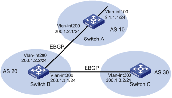
Networking and Configuration Requirements
Switch B establishes eBGP connections with Switch A and C. Configure No_Export community attribute on Switch A to make routes from AS 10 not advertised by AS 20 to any other AS.
Applicable Product Matrix
|
Product series |
Software version |
Hardware version |
|
S3610 Series Ethernet Switches |
Release 5301 Release 5303 |
All versions |
|
S5510 Series Ethernet Switches |
Release 5301 Release 5303 |
All versions |
|
S5500-EI Series Ethernet Switches |
Release 2102 |
All versions |
|
S7500E Series Ethernet Switches |
Release 6100 Release 6300 |
All versions |
Configuration Procedure
1) Configure IP addresses for interfaces (omitted)
2) Configure eBGP
# Configure Switch A. Enable BGP on it, and assign it router ID 1.1.1.1.
<SwitchA> system-view
[SwitchA] bgp 10
[SwitchA-bgp] router-id 1.1.1.1
[SwitchA-bgp] peer 200.1.2.2 as-number 20
[SwitchA-bgp] network 9.1.1.0 255.255.255.0
[SwitchA-bgp] quit
# Configure Switch B. Enable BGP on it, and assign it router ID 2.2.2.2.
<SwitchB> system-view
[SwitchB] bgp 20
[SwitchB-bgp] router-id 2.2.2.2
[SwitchB-bgp] peer 200.1.2.1 as-number 10
[SwitchB-bgp] peer 200.1.3.2 as-number 30
[SwitchB-bgp] quit
# Configure Switch C. Enable BGP on it, and assign it router ID 3.3.3.3.
<SwitchC> system-view
[SwitchC] bgp 30
[SwitchC-bgp] router-id 3.3.3.3
[SwitchC-bgp] peer 200.1.3.1 as-number 20
[SwitchC-bgp] quit
# Display the BGP routing table on Switch B.
[SwitchB] display bgp routing-table 9.1.1.0
BGP local router ID : 2.2.2.2
Local AS number : 20
Paths: 1 available, 1 best
BGP routing table entry information of 9.1.1.0/24:
From : 200.1.2.1 (1.1.1.1)
Original nexthop: 200.1.2.1
AS-path : 10
Origin : igp
Attribute value : MED 0, pref-val 0, pre 255
State : valid, external, best,
Advertised to such 1 peers:
200.1.3.2
Switch B advertised routes to Switch C in AS30.
# Display the routing table on Switch C.
[SwitchC] display bgp routing-table
Total Number of Routes: 1
BGP Local router ID is 3.3.3.3
Status codes: * - valid, > - best, d - damped,
h - history, i - internal, s - suppressed, S - Stale
Origin : i - IGP, e - EGP, ? - incomplete
Network NextHop MED LocPrf PrefVal Path/Ogn
*> 9.1.1.0/24 200.1.3.1 0 20 10i
Switch C learned route 9.1.1.0/24 from Switch B.
3) Configure BGP community
# Configure a routing policy.
[SwitchA] route-policy comm_policy permit node 0
[SwitchA-route-policy] apply community no-export
[SwitchA-route-policy] quit
# Apply the routing policy.
[SwitchA] bgp 10
[SwitchA-bgp] peer 200.1.2.2 route-policy comm_policy export
[SwitchA-bgp] peer 200.1.2.2 advertise-community
# Display the routing table on Switch B.
[SwitchB] display bgp routing-table 9.1.1.0
BGP local router ID : 2.2.2.2
Local AS number : 20
Paths: 1 available, 1 best
BGP routing table entry information of 9.1.1.0/24:
From : 200.1.2.1 (1.1.1.1)
Original nexthop: 200.1.2.1
Community : No-Export
AS-path : 10
Origin : igp
Attribute value : MED 0, pref-val 0, pre 255
State : valid, external, best,
Not advertised to any peers yet
The route 9.1.1.0/24 is not available in the routing table of Switch C.
Complete Configuration
l Conifigure Switch A
#
vlan 100
#
vlan 200
#
interface Vlan-interface100
ip address 9.1.1.1 255.255.255.0
#
interface Vlan-interface200
ip address 200.1.2.1 255.255.255.0
#
bgp 10
router-id 1.1.1.1
network 9.1.1.0 255.255.255.0
undo synchronization
peer 200.1.2.2 as-number 20
peer 200.1.2.2 route-policy comm_policy export
peer 200.1.2.2 advertise-community
#
route-policy comm_policy permit node 0
apply community no-export
#
l Conifigure Switch B
#
vlan 200
#
vlan 300
#
interface Vlan-interface200
ip address 200.1.2.2 255.255.255.0
#
interface Vlan-interface300
ip address 200.1.3.1 255.255.255.0
#
bgp 20
router-id 2.2.2.2
undo synchronization
peer 200.1.2.1 as-number 10
peer 200.1.3.2 as-number 30
#
l Conifigure Switch C
#
vlan 300
#
interface Vlan-interface300
ip address 200.1.3.2 255.255.255.0
#
bgp 30
router-id 3.3.3.3
undo synchronization
peer 200.1.3.1 as-number 20
#
Configuration Guidelines
When configuring BGP community, you need to configure a routing policy to define the community attribute, and apply the routing policy to route advertisement.
Configuring BGP Route Reflector
IBGP peers should be fully meshed to maintain connectivity. If there are n routers in an AS, the number of IBGP connections is n (n-1)/2. Therefore if there are many IBGP peers, most network and CPU resources will be consumed.
Using route reflectors can solve the issue. In an AS, a router acts as a route reflector, and other routers act as clients connecting to the route reflector. The route reflector forwards (reflects) routing information between clients. BGP connections between clients need not be established.
The router neither a route reflector nor a client is a non-client, which has to establish connections to the route reflector and non-clients.
Network Diagram
Figure 1-22 Network diagram for confederation configuration
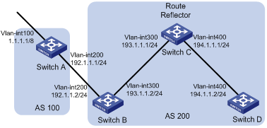
Networking and Configuration Requirements
In the figure above, all the switches run BGP.
l Between Switch A and Switch B is an eBGP connection, between Switch C and Switch B, and between Switch C and Switch D are iBGP connections.
l Switch C is a route reflector with clients Switch B and D.
l Switch D can learn route 1.0.0.0/8 from Switch C.
Applicable Product Matrix
|
Product series |
Software version |
Hardware version |
|
S3610 series Etherenet switches |
Release 5301 Release 5303 |
All versions |
|
S5510 series Etherenet switches |
Release 5301 Release 5303 |
All versions |
|
S5500-EI series Etherenet switches |
Release 2102 |
All versions |
|
S7500E series Etherenet switches |
Release 6100 Release 6300 |
All versions |
Configuration Procedure
1) Configure IP addresses for interfaces (omitted)
2) Configure BGP connections
# Configure Switch A. Enable BGP on it, and assign it router ID 1.1.1.1.
<SwitchA> system-view
[SwitchA] bgp 100
[SwitchA-bgp] router-id 1.1.1.1
[SwitchA-bgp] peer 192.1.1.2 as-number 200
# Inject network 1.0.0.0/8 to the BGP routing table.
[SwitchA-bgp] network 1.0.0.0
[SwitchA-bgp] quit
# Configure Switch B. Enable BGP on it, and assign it router ID 2.2.2.2.
<SwitchB> system-view
[SwitchB] bgp 200
[SwitchB-bgp] router-id 2.2.2.2
[SwitchB-bgp] peer 192.1.1.1 as-number 100
[SwitchB-bgp] peer 193.1.1.1 as-number 200
[SwitchB-bgp] peer 193.1.1.1 next-hop-local
[SwitchB-bgp] quit
# Configure Switch C. Enable BGP on it, and assign it router ID 3.3.3.3.
<SwitchC> system-view
[SwitchC] bgp 200
[SwitchC-bgp] router-id 3.3.3.3
[SwitchC-bgp] peer 193.1.1.2 as-number 200
[SwitchC-bgp] peer 194.1.1.2 as-number 200
[SwitchC-bgp] quit
# Configure Switch D. Enable BGP on it, and assign it router ID 4.4.4.4.
<SwitchD> system-view
[SwitchD] bgp 200
[SwitchD-bgp] router-id 4.4.4.4
[SwitchD-bgp] peer 194.1.1.1 as-number 200
[SwitchD-bgp] quit
Configure the route reflector
# Configure Switch C.
[SwitchC] bgp 200
[SwitchC-bgp] peer 193.1.1.2 reflect-client
[SwitchC-bgp] peer 194.1.1.2 reflect-client
[SwitchC-bgp] quit
Verify the configuration
# Display the BGP routing table on Switch B.
[SwitchB] display bgp routing-table
Total Number of Routes: 1
BGP Local router ID is 2.2.2.2
Status codes: * - valid, > - best, d - damped,
h - history, i - internal, s - suppressed, S - Stale
Origin : i - IGP, e - EGP, ? - incomplete
Network NextHop MED LocPrf PrefVal Path/Ogn
*> 1.0.0.0 192.1.1.1 0 0 100i
# Display the BGP routing table on Switch D.
[SwitchD] display bgp routing-table
Total Number of Routes: 1
BGP Local router ID is 4.4.4.4
Status codes: * - valid, > - best, d - damped,
h - history, i - internal, s - suppressed, S - Stale
Origin : i - IGP, e - EGP, ? - incomplete
Network NextHop MED LocPrf PrefVal Path/Ogn
i 1.0.0.0 193.1.1.2 0 100 0 100i
Switch D learned route 1.0.0.0/8 from Switch C.
Complete Configuration
l Configure Switch A
#
vlan 100
#
vlan 200
#
interface Vlan-interface100
ip address 1.1.1.1 255.0.0.0
#
interface Vlan-interface200
ip address 192.1.1.1 255.255.255.0
#
bgp 100
router-id 1.1.1.1
network 1.0.0.0
undo synchronization
peer 192.1.1.2 as-number 200
#
l Configure Switch B
#
vlan 200
#
vlan 300
#
interface Vlan-interface200
ip address 192.1.1.2 255.255.255.0
#
interface Vlan-interface300
ip address 193.1.1.2 255.255.255.0
#
bgp 200
router-id 2.2.2.2
undo synchronization
peer 192.1.1.1 as-number 100
peer 193.1.1.1 as-number 200
peer 193.1.1.1 next-hop-local
#
l Configure Switch C
#
vlan 300
#
vlan 400
#
interface Vlan-interface300
ip address 193.1.1.1 255.255.255.0
#
interface Vlan-interface400
ip address 194.1.1.1 255.255.255.0
#
bgp 200
router-id 3.3.3.3
undo synchronization
peer 193.1.1.2 as-number 200
peer 194.1.1.2 as-number 200
peer 193.1.1.2 reflect-client
peer 194.1.1.2 reflect-client
#
l Configure Switch D
#
vlan 400
#
interface Vlan-interface400
ip address 194.1.1.2 255.255.255.0
#
bgp 200
router-id 4.4.4.4
undo synchronization
peer 194.1.1.1 as-number 200
#
Configuration Guidelines
l In general, it is not required to make clients of a route reflector fully meshed. The route reflector forwards routing information between clients. If clients are fully meshed, you can disable route reflection between clients to reduce routing costs.
l After route reflection is disabled between clients, routes between a client and a non-client can still be reflected.
l In general, a cluster has only one route reflector, and the router ID is used to identify the cluster. You can configure multiple route reflectors to improve network stability. In this case, you need to specify the same cluster ID for these route reflectors to avoid routing loops.
Configuring BGP Confederation
Confederation is another method to deal with growing IBGP connections in ASs. It splits an AS into multiple sub-ASs. In each sub-AS, IBGP peers are fully meshed, and EBGP connections are established between sub-ASs
From the perspective of a non-confederation speaker, it needs not know sub-ASs in the confederation. The ID of the confederation is the number of the AS.
The deficiency of confederation is: when changing an AS into a confederation, you need to reconfigure your routers, and the topology will be changed.
In large-scale BGP networks, both route reflector and confederation can be used.
Network Diagram
Figure 1-23 Network diagram for BGP path selection configuration
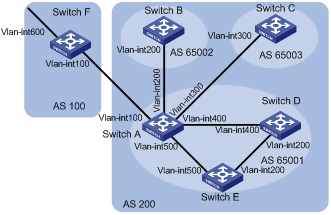
|
Device |
Interface |
IP address |
Device |
Interface |
IP address |
|
Switch A |
Vlan-int100 |
200.1.1.1/24 |
Switch D |
Vlan-int200 |
10.1.5.1/24 |
|
|
Vlan-int200 |
10.1.1.1/24 |
|
Vlan-int400 |
10.1.3.2/24 |
|
|
Vlan-int300 |
10.1.2.1/24 |
Switch E |
Vlan-int200 |
10.1.5.2/24 |
|
|
Vlan-int400 |
10.1.3.1/24 |
|
Vlan-int500 |
10.1.4.2/24 |
|
|
Vlan-int500 |
10.1.4.1/24 |
Switch F |
Vlan-int100 |
200.1.1.2/24 |
|
Switch B |
Vlan-int200 |
10.1.1.2/24 |
|
Vlan-int600 |
9.1.1.1/24 |
|
Switch C |
Vlan-int300 |
10.1.2.2/24 |
|
|
|
Networking and Configuration Requirements
To reduce iBGP connections in AS 200, split it into three sub-ASs, AS65001, AS65002 and AS65003. Switches in AS65001 are fully meshed.
Applicable Product Matrix
|
Product series |
Software version |
Hardware version |
|
S3610 series Etherent switches |
Release 5301 Release 5303 |
All versions |
|
S5510 series Etherent switches |
Release 5301 Release 5303 |
All versions |
|
S5500-EI series Etherent switches |
Release 2102 |
All versions |
|
S7500E series Etherent switches |
Release 6100 Release 6300 |
All versions |
Configuration Procedure
1) Configure IP addresses for interfaces (omitted)
2) Configure BGP confederation
# Configure Switch A.
<SwitchA> system-view
[SwitchA] bgp 65001
[SwitchA-bgp] router-id 1.1.1.1
[SwitchA-bgp] confederation id 200
[SwitchA-bgp] confederation peer-as 65002 65003
[SwitchA-bgp] peer 10.1.1.2 as-number 65002
[SwitchA-bgp] peer 10.1.1.2 next-hop-local
[SwitchA-bgp] peer 10.1.2.2 as-number 65003
[SwitchA-bgp] peer 10.1.2.2 next-hop-local
[SwitchA-bgp] quit
# Configure Switch B.
<SwitchB> system-view
[SwitchB] bgp 65002
[SwitchB-bgp] router-id 2.2.2.2
[SwitchB-bgp] confederation id 200
[SwitchB-bgp] confederation peer-as 65001 65003
[SwitchB-bgp] peer 10.1.1.1 as-number 65001
[SwitchB-bgp] quit
# Configure Switch C.
<SwitchC> system-view
[SwitchC] bgp 65003
[SwitchC-bgp] router-id 3.3.3.3
[SwitchC-bgp] confederation id 200
[SwitchC-bgp] confederation peer-as 65001 65002
[SwitchC-bgp] peer 10.1.2.1 as-number 65001
[SwitchC-bgp] quit
3) Configure iBGP connections in AS65001.
# Configure Switch A.
[SwitchA] bgp 65001
[SwitchA-bgp] peer 10.1.3.2 as-number 65001
[SwitchA-bgp] peer 10.1.3.2 next-hop-local
[SwitchA-bgp] peer 10.1.4.2 as-number 65001
[SwitchA-bgp] peer 10.1.4.2 next-hop-local
[SwitchA-bgp] quit
# Configure Switch D.
<SwitchD> system-view
[SwitchD] bgp 65001
[SwitchD-bgp] router-id 4.4.4.4
[SwitchD-bgp] confederation id 200
[SwitchD-bgp] peer 10.1.3.1 as-number 65001
[SwitchD-bgp] peer 10.1.5.2 as-number 65001
[SwitchD-bgp] quit
# Configure Switch E.
<SwitchE> system-view
[SwitchE] bgp 65001
[SwitchE-bgp] router-id 5.5.5.5
[SwitchE-bgp] confederation id 200
[SwitchE-bgp] peer 10.1.4.1 as-number 65001
[SwitchE-bgp] peer 10.1.5.1 as-number 65001
[SwitchE-bgp] quit
4) Configure the eBGP connection between AS100 and AS200.
# Configure Switch A.
[SwitchA] bgp 65001
[SwitchA-bgp] peer 200.1.1.2 as-number 100
[SwitchA-bgp] quit
# Configure Switch F.
<SwitchF> system-view
[SwitchF] bgp 100
[SwitchF-bgp] router-id 6.6.6.6
[SwitchF-bgp] peer 200.1.1.1 as-number 200
[SwitchF-bgp] network 9.1.1.0 255.255.255.0
[SwitchF-bgp] quit
5) Verify the configuration
# Display the routing table on Switch B.
[SwitchB] display bgp routing-table
Total Number of Routes: 1
BGP Local router ID is 2.2.2.2
Status codes: * - valid, > - best, d - damped,
h - history, i - internal, s - suppressed, S - Stale
Origin : i - IGP, e - EGP, ? - incomplete
Network NextHop MED LocPrf PrefVal Path/Ogn
*>i 9.1.1.0/24 10.1.1.1 0 100 0 (65001) 100i
[SwitchB] display bgp routing-table 9.1.1.0
BGP local router ID : 2.2.2.2
Local AS number : 65002
Paths: 1 available, 1 best
BGP routing table entry information of 9.1.1.0/24:
From : 10.1.1.1 (1.1.1.1)
Relay Nexthop : 0.0.0.0
Original nexthop: 10.1.1.1
AS-path : (65001) 100
Origin : igp
Attribute value : MED 0, localpref 100, pref-val 0, pre 255
State : valid, external-confed, best,
Not advertised to any peers yet
# Display the BGP routing table on Switch D.
[SwitchD] display bgp routing-table
Total Number of Routes: 1
BGP Local router ID is 4.4.4.4
Status codes: * - valid, > - best, d - damped,
h - history, i - internal, s - suppressed, S - Stale
Origin : i - IGP, e - EGP, ? - incomplete
Network NextHop MED LocPrf PrefVal Path/Ogn
*>i 9.1.1.0/24 10.1.3.1 0 100 0 100i
[SwitchD] display bgp routing-table 9.1.1.0
BGP local router ID : 4.4.4.4
Local AS number : 65001
Paths: 1 available, 1 best
BGP routing table entry information of 9.1.1.0/24:
From : 10.1.3.1 (1.1.1.1)
Relay Nexthop : 0.0.0.0
Original nexthop: 10.1.3.1
AS-path : 100
Origin : igp
Attribute value : MED 0, localpref 100, pref-val 0, pre 255
State : valid, internal, best,
Not advertised to any peers yet
Complete Configuration
l Configure Switch A
#
vlan 100
#
vlan 200
#
vlan 300
#
vlan 400
#
vlan 500
#
interface Vlan-interface100
ip address 200.1.1.1 255.255.255.0
#
interface Vlan-interface200
ip address 10.1.1.1 255.255.255.0
#
interface Vlan-interface300
ip address 10.1.2.1 255.255.255.0
#
interface Vlan-interface400
ip address 10.1.3.1 255.255.255.0
#
interface Vlan-interface500
ip address 10.1.4.1 255.255.255.0
#
bgp 65001
router-id 1.1.1.1
confederation id 200
confederation peer-as 65002 65003
undo synchronization
peer 10.1.4.2 as-number 65001
peer 10.1.1.2 as-number 65002
peer 200.1.1.2 as-number 100
peer 10.1.2.2 as-number 65003
peer 10.1.3.2 as-number 65001
peer 10.1.4.2 next-hop-local
peer 10.1.1.2 next-hop-local
peer 10.1.2.2 next-hop-local
peer 10.1.3.2 next-hop-local
#
l Configure Switch B
#
vlan 100
#
interface Vlan-interface100
ip address 10.1.1.2 255.255.255.0
#
bgp 65002
router-id 2.2.2.2
confederation id 200
confederation peer-as 65001 65003
undo synchronization
peer 10.1.1.1 as-number 65001
l Configure Switch C
#
vlan 100
#
interface Vlan-interface100
ip address 10.1.2.2 255.255.255.0
#
bgp 65003
router-id 3.3.3.3
confederation id 200
confederation peer-as 65001 65002
undo synchronization
peer 10.1.2.1 as-number 65001
#
l Configure Switch D
#
vlan 100
#
vlan 200
#
interface Vlan-interface100
ip address 10.1.3.2 255.255.255.0
#
interface Vlan-interface200
ip address 10.1.5.1 255.255.255.0
#
bgp 65001
router-id 4.4.4.4
confederation id 200
undo synchronization
peer 10.1.5.2 as-number 65001
peer 10.1.3.1 as-number 65001
#
l Configure Switch E
#
vlan 100
#
vlan 200
#
interface Vlan-interface100
ip address 10.1.4.2 255.255.255.0
#
interface Vlan-interface200
ip address 10.1.5.2 255.255.255.0
#
bgp 65001
router-id 5.5.5.5
confederation id 200
undo synchronization
peer 10.1.4.1 as-number 65001
peer 10.1.5.1 as-number 65001
#
l Configure Switch F
#
vlan 100
#
vlan 200
#
interface Vlan-interface100
ip address 9.1.1.1 255.255.255.0
#
interface Vlan-interface200
ip address 200.1.1.2 255.255.255.0
#
bgp 100
router-id 6.6.6.6
network 9.1.1.0 255.255.255.0
undo synchronization
peer 200.1.1.1 as-number 200
#
Configuration Guidelines
If the confederation implementation mechanism of other routers is different from the RFC specifications, you can use the confederation nonstandard command to make the confederation compatible with the non-standard routers.
Configuring BGP Path Selection
The current BGP implementation supports the following route selection sequence:
l Discard routes with unreachable NEXT_HOPs first
l Select the route with the highest Preferred_value
l Select the route with the highest LOCAL_PREF
l Select the route originated by the local router
l Select the route with the shortest AS-PATH
l Select IGP, EGP, Incomplete routes in turn
l Select the route with the lowest MED value
l Select routes learned from eBGP, confederation, iBGP in turn
l Select the route with the smallest next hop cost
l Select the route with the shortest CLUSTER_LIST
l Select the route with the smallest ORIGINATOR_ID
l Select the route advertised by the router with the smallest Router ID
Network Diagram
Figure 1-24 Network diagram for route policy application in IPv4 route redistribution
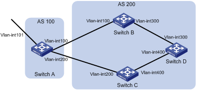
|
Interface |
IP address |
Device |
Interface |
IP address |
|
|
Switch A |
Vlan-int101 |
1.0.0.1/8 |
Switch D |
Vlan-int400 |
195.1.1.1/24 |
|
|
Vlan-int100 |
192.1.1.1/24 |
|
Vlan-int300 |
194.1.1.1/24 |
|
|
Vlan-int200 |
193.1.1.1/24 |
Switch C |
Vlan-int400 |
195.1.1.2/24 |
|
Switch B |
Vlan-int100 |
192.1.1.2/24 |
|
Vlan-int200 |
193.1.1.2/24 |
|
|
Vlan-int300 |
194.1.1.2/24 |
|
|
|
Networking and Configuration Requirements
l In the below above, all switches run BGP. Between Switch A and Switch B, and between Switch A and Switch C are eBGP connections. Between Switch B and Switch D, and between Switch D and Switch C are iBGP connections.
l OSPF is the IGP protocol in AS 200.
l Configure routing policies, making Switch D use the route 1.0.0.0/8 from Switch C as the optimal.
Applicable Product Matrix
|
Product series |
Software version |
Hardware version |
|
S3610 Series Ethernet Switches |
Release 5301 Release 5303 |
All versions |
|
S5510 Series Ethernet Switches |
Release 5301 Release 5303 |
All versions |
|
S5500-EI Series Ethernet Switches |
Release 2102 |
All versions |
|
S7500E Series Ethernet Switches |
Release 6100 Release 6300 |
All versions |
Configuration Procedure
1) Configure IP addresses for interfaces (omitted).
2) Configure OSPF on Switch B, C, and D.
# Configure Switch B.
<SwitchB> system-view
[SwitchB] ospf
[SwitchB-ospf] area 0
[SwitchB-ospf-1-area-0.0.0.0] network 192.1.1.0 0.0.0.255
[SwitchB-ospf-1-area-0.0.0.0] network 194.1.1.0 0.0.0.255
[SwitchB-ospf-1-area-0.0.0.0] quit
[SwitchB-ospf-1] quit
# Configure Switch C.
<SwitchC> system-view
[SwitchC] ospf
[SwitchC-ospf] area 0
[SwitchC-ospf-1-area-0.0.0.0] network 193.1.1.0 0.0.0.255
[SwitchC-ospf-1-area-0.0.0.0] network 195.1.1.0 0.0.0.255
[SwitchC-ospf-1-area-0.0.0.0] quit
[SwitchC-ospf-1] quit
# Configure Switch D.
<SwitchD> system-view
[SwitchD] ospf
[SwitchD-ospf] area 0
[SwitchD-ospf-1-area-0.0.0.0] network 194.1.1.0 0.0.0.255
[SwitchD-ospf-1-area-0.0.0.0] network 195.1.1.0 0.0.0.255
[SwitchD-ospf-1-area-0.0.0.0] quit
[SwitchD-ospf-1] quit
3) Configure BGP connections
# Configure Switch A.
<SwitchA> system-view
[SwitchA] bgp 100
[SwitchA-bgp] peer 192.1.1.2 as-number 200
[SwitchA-bgp] peer 193.1.1.2 as-number 200
# Inject network 1.0.0.0/8 to the BGP routing table on Switch A.
[SwitchA-bgp] network 1.0.0.0 8
[SwitchA-bgp] quit
# Configure Switch B.
[SwitchB] bgp 200
[SwitchB-bgp] peer 192.1.1.1 as-number 100
[SwitchB-bgp] peer 194.1.1.1 as-number 200
[SwitchB-bgp] quit
# Configure Switch C.
[SwitchC] bgp 200
[SwitchC-bgp] peer 193.1.1.1 as-number 100
[SwitchC-bgp] peer 195.1.1.1 as-number 200
[SwitchC-bgp] quit
# Configure Switch D.
[SwitchD] bgp 200
[SwitchD-bgp] peer 194.1.1.2 as-number 200
[SwitchD-bgp] peer 195.1.1.2 as-number 200
[SwitchD-bgp] quit
4) Configure attributes for route 1.0.0.0/8, making Switch D give priority to the route learned from Switch C.
l Configure a higher MED value for the route 1.0.0.0/8 advertised from Switch A to peer 192.1.1.2.
# Define an ACL numbered 2000 to permit route 1.0.0.0/8.
[SwitchA] acl number 2000
[SwitchA-acl-basic-2000] rule permit source 1.0.0.0 0.255.255.255
[SwitchA-acl-basic-2000] quit
# Define two routing policies, apply_med_50, which sets the MED for route 1.0.0.0/8 to 50, and apply_med_100, which sets the MED for route 1.0.0.0/8 to 100.
[SwitchA] route-policy apply_med_50 permit node 10
[SwitchA-route-policy] if-match acl 2000
[SwitchA-route-policy] apply cost 50
[SwitchA-route-policy] quit
[SwitchA] route-policy apply_med_100 permit node 10
[SwitchA-route-policy] if-match acl 2000
[SwitchA-route-policy] apply cost 100
[SwitchA-route-policy] quit
# Apply routing policy apply_med_50 to the route advertised to peer 193.1.1.2 (Switch C), and apply_med_100 to the route advertised to peer 192.1.1.2 (Switch B).
[SwitchA] bgp 100
[SwitchA-bgp] peer 193.1.1.2 route-policy apply_med_50 export
[SwitchA-bgp] peer 192.1.1.2 route-policy apply_med_100 export
[SwitchA-bgp] quit
# Display the BGP routing table on Switch D.
[SwitchD] display bgp routing-table
Total Number of Routes: 2
BGP Local router ID is 194.1.1.1
Status codes: * - valid, > - best, d - damped,
h - history, i - internal, s - suppressed, S - Stale
Origin : i - IGP, e - EGP, ? - incomplete
Network NextHop MED LocPrf PrefVal Path/Ogn
*>i 1.0.0.0 193.1.1.1 50 100 0 100i
* i 192.1.1.1 100 100 0 100i
You can find route 1.0.0.0/8 is the optimal.
l Configure different local preferences on Switch B and C for route 1.0.0.0/8, making Switch D give priority to the route from Switch C.
# Define an ACL numbered 2000 on Router C, permitting route 1.0.0.0/8.
[SwitchC] acl number 2000
[SwitchC-acl-basic-2000] rule permit source 1.0.0.0 0.255.255.255
[SwitchC-acl-basic-2000] quit
# Configure a routing policy named localpref on Switch C, setting the local preference of route 1.0.0.0/8 to 200 (the default is 100).
[SwitchC] route-policy localpref permit node 10
[SwitchC-route-policy] if-match acl 2000
[SwitchC-route-policy] apply local-preference 200
[SwitchC-route-policy] quit
# Apply routing policy localpref to routes from peer 193.1.1.1.
[SwitchC] bgp 200
[SwitchC-bgp] peer 193.1.1.1 route-policy localpref import
[SwitchC-bgp] quit
# Display the routing table on Switch D.
[SwitchD] display bgp routing-table
Total Number of Routes: 2
BGP Local router ID is 194.1.1.1
Status codes: * - valid, > - best, d - damped,
h - history, i - internal, s - suppressed, S - Stale
Origin : i - IGP, e - EGP, ? - incomplete
Network NextHop MED LocPrf PrefVal Path/Ogn
*>i 1.0.0.0 193.1.1.1 0 200 0 100i
* i 192.1.1.1 0 100 0 100i
You can find route 1.0.0.0/8 from Switch D to Switch C is the optimal.
Complete Configuration
l Configure Switch A
#
vlan 100 to 101
#
vlan 200
#
acl number 2000
rule 0 permit source 1.0.0.0 0.255.255.255
#
interface Vlan-interface100
ip address 192.1.1.1 255.255.255.0
#
interface Vlan-interface101
ip address 1.0.0.1 255.0.0.0
#
interface Vlan-interface200
ip address 193.1.1.1 255.255.255.0
#
bgp 100
network 1.0.0.0
undo synchronization
peer 192.1.1.2 as-number 200
peer 193.1.1.2 as-number 200
peer 192.1.1.2 route-policy apply_med_100 export
peer 193.1.1.2 route-policy apply_med_50 export
#
route-policy apply_med_50 permit node 10
if-match acl 2000
apply cost 50
route-policy apply_med_100 permit node 10
if-match acl 2000
apply cost 100
#
l Configure Switch B
#
vlan 100
#
vlan 300
#
interface Vlan-interface100
ip address 192.1.1.2 255.255.255.0
#
interface Vlan-interface300
ip address 194.1.1.2 255.255.255.0
#
bgp 200
undo synchronization
peer 192.1.1.1 as-number 100
peer 194.1.1.1 as-number 200
#
ospf 1
area 0.0.0.0
network 192.1.1.0 0.0.0.255
network 194.1.1.0 0.0.0.255
#
l Configure Switch C
#
vlan 200
#
vlan 400
#
acl number 2000
rule 0 permit source 1.0.0.0 0.255.255.255
#
interface Vlan-interface200
ip address 193.1.1.2 255.255.255.0
#
interface Vlan-interface400
ip address 195.1.1.2 255.255.255.0
#
bgp 200
undo synchronization
peer 193.1.1.1 as-number 100
peer 195.1.1.1 as-number 200
peer 193.1.1.1 route-policy localpref import
#
ospf 1
area 0.0.0.0
network 193.1.1.0 0.0.0.255
network 195.1.1.0 0.0.0.255
#
route-policy localpref permit node 10
if-match acl 2000
apply local-preference 200
#
l Configure Switch D
#
vlan 300
#
vlan 400
#
interface Vlan-interface300
ip address 194.1.1.1 255.255.255.0
#
interface Vlan-interface400
ip address 195.1.1.1 255.255.255.0
#
bgp 200
undo synchronization
peer 194.1.1.2 as-number 200
peer 195.1.1.2 as-number 200
#
ospf 1
area 0.0.0.0
network 194.1.1.0 0.0.0.255
network 195.1.1.0 0.0.0.255
#
Configuration Guidelines
None
Configuring Route Policy Application in IPv4 Route Redistribution
A routing policy is used on the router for route inspection, filtering, attributes modifying when routes are received, advertised, or redistributed.
When distributing or receiving routing information, a router can use a routing policy to filter routing information. For example, a router receives or advertises only routing information that matches the criteria of a routing policy; a routing protocol redistributes routes from another protocol only routes matching the criteria of a routing policy and modifies some attributes of these routes to satisfy its needs using the routing policy.
To implement a routing policy, you need to define a set of match criteria according to attributes in routing information, such as destination address, advertising router’s address and so on. The match criteria can be set beforehand and then apply them to a routing policy for route distribution, reception and redistribution.
Network Diagram
Figure 1-25 Route policy configuration to filter received BGP routes
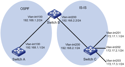
Networking and Configuration Requirements
l As shown in the figure above, Switch B exchanges routing information with Switch A using OSPF, and with Switch C using IS-IS.
l On Switch B, enable route redistribution from IS-IS to OSPF and apply a route policy to set the cost of route 172.17.1.0/24 to 100, and the tag of route 172.17.2.0/24 to 20.
Applicable Product Matrix
|
Product series |
Software version |
Hardware version |
|
S3610 Series Ethernet Switches |
Release 5301 Release 5303 |
All versions |
|
S5510 Series Ethernet Switches |
Release 5301 Release 5303 |
All versions |
|
S5500-EI Series Ethernet Switches |
Release 2102 |
All versions |
|
S7500E Series Ethernet Switches |
Release 6100 Release 6300 |
All versions |
Configuration Procedure
1) Specify IP addresses for interfaces (omitted).
2) Configure IS-IS.
# Configure Switch C.
<SwitchC> system-view
[SwitchC] isis
[SwitchC-isis-1] is-level level-2
[SwitchC-isis-1] network-entity 10.0000.0000.0001.00
[SwitchC-isis-1] quit
[SwitchC] interface vlan-interface 200
[SwitchC-Vlan-interface200] isis enable
[SwitchC-Vlan-interface200] quit
[SwitchC] interface vlan-interface 201
[SwitchC-Vlan-interface201] isis enable
[SwitchC-Vlan-interface201] quit
[SwitchC] interface vlan-interface 202
[SwitchC-Vlan-interface202] isis enable
[SwitchC-Vlan-interface202] quit
[SwitchC] interface vlan-interface 203
[SwitchC-Vlan-interface203] isis enable
[SwitchC-Vlan-interface203] quit
# Configure Switch B.
<SwitchB> system-view
[SwitchB] isis
[SwitchB-isis-1] is-level level-2
[SwitchB-isis-1] network-entity 10.0000.0000.0002.00
[SwitchB-isis-1] quit
[SwitchB] interface vlan-interface 200
[SwitchB-Vlan-interface200] isis enable
[SwitchB-Vlan-interface200] quit
3) Configure OSPF and route redistribution
# Configure OSPF on Switch A.
<SwitchA> system-view
[SwitchA] ospf
[SwitchA-ospf-1] area 0
[SwitchA-ospf-1-area-0.0.0.0] network 192.168.1.0 0.0.0.255
[SwitchA-ospf-1-area-0.0.0.0] quit
[SwitchA-ospf-1] quit
# On Switch B, configure OSPF and enable route redistribution from IS-IS.
[SwitchB] ospf
[SwitchB-ospf-1] area 0
[SwitchB-ospf-1-area-0.0.0.0] network 192.168.1.0 0.0.0.255
[SwitchB-ospf-1-area-0.0.0.0] quit
[SwitchB-ospf-1] import-route isis 1
[SwitchB-ospf-1] quit
# Display the OSPF routing table on Switch A to view redistributed routes.
[SwitchA] display ospf routing
OSPF Process 1 with Router ID 192.168.1.1
Routing Tables
Routing for Network
Destination Cost Type NextHop AdvRouter Area
192.168.1.0/24 1562 Stub 192.168.1.1 192.168.1.1 0.0.0.0
Routing for ASEs
Destination Cost Type Tag NextHop AdvRouter
172.17.1.0/24 1 Type2 1 192.168.1.2 192.168.2.2
172.17.2.0/24 1 Type2 1 192.168.1.2 192.168.2.2
172.17.3.0/24 1 Type2 1 192.168.1.2 192.168.2.2
Total Nets: 4
Intra Area: 1 Inter Area: 0 ASE: 3 NSSA: 0
4) Configure filtering lists
# Configure ACL 2002 to permit route 172.17.2.0/24.
[SwitchB] acl number 2002
[SwitchB-acl-basic-2002] rule permit source 172.17.2.0 0.0.0.255
[SwitchB-acl-basic-2002] quit
# Configure IP prefix list prefix-a to permit route 172.17.1.0/24.
[SwitchB] ip ip-prefix prefix-a index 10 permit 172.17.1.0 24
5) Configure a route policy.
[SwitchB] route-policy isis2ospf permit node 10
[SwitchB-route-policy] if-match ip-prefix prefix-a
[SwitchB-route-policy] apply cost 100
[SwitchB-route-policy] quit
[SwitchB] route-policy isis2ospf permit node 20
[SwitchB-route-policy] if-match acl 2002
[SwitchB-route-policy] apply tag 20
[SwitchB-route-policy] quit
[SwitchB] route-policy isis2ospf permit node 30
[SwitchB-route-policy] quit
6) Apply the route policy to route redistribution.
# On Switch B, apply the route policy when redistributing routes.
[SwitchB] ospf
[SwitchB-ospf-1] import-route isis 1 route-policy isis2ospf
[SwitchB-ospf-1] quit
# Display the OSPF routing table on Switch A. The cost of route 172.17.1.0/24 is 100, the tag of route 172.17.1.0/24 is 20.
[SwitchA] display ospf routing
OSPF Process 1 with Router ID 192.168.1.1
Routing Tables
Routing for Network
Destination Cost Type NextHop AdvRouter Area
192.168.1.0/24 1 Transit 192.168.1.1 192.168.1.1 0.0.0.0
Routing for ASEs
Destination Cost Type Tag NextHop AdvRouter
172.17.1.0/24 100 Type2 1 192.168.1.2 192.168.2.2
172.17.2.0/24 1 Type2 20 192.168.1.2 192.168.2.2
172.17.3.0/24 1 Type2 1 192.168.1.2 192.168.2.2
192.168.2.0/24 1 Type2 1 192.168.1.2 192.168.2.2
Total Nets: 5
Intra Area: 1 Inter Area: 0 ASE: 4 NSSA: 0
Complete Configuration
l Configure Switch A
#
vlan 100
#
interface Vlan-interface100
ip address 192.168.1.1 255.255.255.0
#
ospf 1
area 0.0.0.0
network 192.168.1.0 0.0.0.255
#
l Configure Switch B
#
vlan 100
#
vlan 200
#
isis 1
is-level level-2
network-entity 10.0000.0000.0002.00
#
acl number 2002
rule 0 permit source 172.17.2.0 0.0.0.255
#
interface Vlan-interface100
ip address 192.168.1.2 255.255.255.0
#
interface Vlan-interface200
ip address 192.168.2.2 255.255.255.0
isis enable 1
#
ospf 1
import-route isis 1 route-policy isis2ospf
area 0.0.0.0
network 192.168.1.0 0.0.0.255
#
route-policy isis2ospf permit node 10
if-match ip-prefix prefix-a
apply cost 100
route-policy isis2ospf permit node 20
if-match acl 2002
apply tag 20
route-policy isis2ospf permit node 30
#
ip ip-prefix prefix-a index 10 permit 172.17.1.0 24
#
l Configure Switch C
#
vlan 200 to 203
#
isis 1
is-level level-2
network-entity 10.0000.0000.0001.00
#
interface Vlan-interface200
ip address 192.168.2.1 255.255.255.0
isis enable 1
#
interface Vlan-interface201
ip address 172.17.1.1 255.255.255.0
isis enable 1
#
interface Vlan-interface202
ip address 172.17.2.1 255.255.255.0
isis enable 1
#
interface Vlan-interface203
ip address 172.17.3.1 255.255.255.0
isis enable 1
#
Configuration Guidelines
l If a node has the permit keyword specified, routing information meeting the node’s conditions will be handled using the apply clauses of this node, without needing to match against the next node. If routing information does not meet the node’s conditions, it will go to the next node for a match.
l If a node is specified as deny, the apply clauses of the node will not be executed. When routing information matches all if-match clauses of the node, it can neither pass the node, nor go to the next node. If route information cannot match any if-match clause of the node, it will go to the next node for a match.
l When a routing policy is defined with more than one node, at least one node should be configured with the permit keyword. If the routing policy is used to filter routing information, routing information that does not meet any node’s conditions cannot pass the routing policy. If all nodes of the routing policy are set using the deny keyword, no routing information can pass it.
l The if-match clauses of a route-policy are in logic AND relationship, namely, routing information has to satisfy all if-match clauses before being executed with apply clauses.
l You can specify no or multiple if-match clauses for a routing policy. If no if-match clause is specified, and the routing policy is in permit mode, all routing information can pass the node; if in deny mode, no routing information can pass.
Applying a Route Policy to Filter Received BGP Routes
Network Diagram
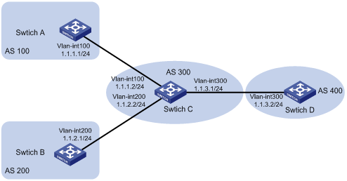
Networking and Configuration Requirements
l All the switches run BGP. Switch C establishes eBGP connections with other switches.
l Configure a route policy on Switch D to reject routes from AS 200.
Applicable Product Matrix
|
Product series |
Software version |
Hardware version |
|
S3610 Series Ethernet Switches |
Release 5301, Release 5303 |
All versions |
|
S5510 Series Ethernet Switches |
Release 5301, Release 5303 |
All versions |
|
S5500-EI Series Ethernet Switches |
Release 2102 |
All versions |
|
S7500E Series Ethernet Switches |
Release 6100, Release 6300 |
All versions |
Configuration Procedure
1) Configure IP addresses for the interfaces (omitted).
2) Configure BGP.
# Configure Switch A.
<SwitchA> system-view
[SwitchA] bgp 100
[SwitchA-bgp] router-id 1.1.1.1
[SwitchA-bgp] peer 1.1.1.2 as-number 300
# Configure Switch B.
<SwitchB> system-view
[SwitchB] bgp 200
[SwitchB-bgp] router-id 2.2.2.2
[SwitchB-bgp] peer 1.1.2.2 as-number 300
# Configure Switch C.
<SwitchC> system-view
[SwitchC] bgp 300
[SwitchC-bgp] router-id 3.3.3.3
[SwitchC-bgp] peer 1.1.1.1 as-number 100
[SwitchC-bgp] peer 1.1.2.1 as-number 200
[SwitchC-bgp] peer 1.1.3.2 as-number 400
# Configure Switch D.
<SwitchD> system-view
[SwitchD] bgp 400
[SwitchD-bgp] router-id 4.4.4.4
[SwitchD-bgp] peer 1.1.3.1 as-number 300
[SwitchD-bgp] quit
# On Switch A, inject routes 4.4.4.4/24, 5.5.5.5/24, and 6.6.6.6/24 to BGP.
[SwitchA-bgp] network 4.4.4.4 24
[SwitchA-bgp] network 5.5.5.5 24
[SwitchA-bgp] network 6.6.6.6 24
# On Switch B, inject routes 7.7.7.7/24, 8.8.8.8/24, and 9.9.9.9/24 to BGP.
[SwitchB-bgp] network 7.7.7.7 24
[SwitchB-bgp] network 8.8.8.8 24
[SwitchB-bgp] network 9.9.9.9 24
# Display the BGP routing table information of Switch D.
[SwitchD-bgp] display bgp routing-table
Total Number of Routes: 6
BGP Local router ID is 4.4.4.4
Status codes: * - valid, > - best, d - damped,
h - history, i - internal, s - suppressed, S - Stale
Origin : i - IGP, e - EGP, ? - incomplete
Network NextHop MED LocPrf PrefVal Path/Ogn
*> 4.4.4.0/24 1.1.3.1 0 300 100i
*> 5.5.5.0/24 1.1.3.1 0 300 100i
*> 6.6.6.0/24 1.1.3.1 0 300 100i
*> 7.7.7.0/24 1.1.3.1 0 300 200i
*> 8.8.8.0/24 1.1.3.1 0 300 200i
*> 9.9.9.0/24 1.1.3.1 0 300 200i
The display above shows that Switch D has learned routes 4.4.4.0/24, 5.5.5.0/24, and 6.6.6.0/24 from AS 100 and 7.7.7.0/24, 8.8.8.0/24, and 9.9.9.0/24 from AS 200.
3) Configure Switch D to reject routes from AS 200.
# Configure AS_PATH list 1 on Switch D.
[SwitchD] ip as-path 1 permit .*200.*
# Configure a route policy named rt1 on Switch D.
[SwitchD] route-policy rt1 deny node 1
[SwitchD] if-match as-path 1
[SwitchD] route-policy rt2 permit node 2
# On Switch D, specify route policy rt1 to filter routes received from peer 1.1.3.1.
[SwitchD] bgp 400
[SwitchD] peer 1.1.3.1 route-policy rt1 import
# Display the BGP routing table information of Switch D.
[SwitchD] display bgp routing-table
Total Number of Routes: 3
BGP Local router ID is 4.4.4.4
Status codes: * - valid, > - best, d - damped,
h - history, i - internal, s - suppressed, S - Stale
Origin : i - IGP, e - EGP, ? - incomplete
Network NextHop MED LocPrf PrefVal Path/Ogn
*> 4.4.4.0/24 1.1.3.1 0 300 100i
*> 5.5.5.0/24 1.1.3.1 0 300 100i
*> 6.6.6.0/24 1.1.3.1 0 300 100i
The display above shows that Switch D has learned only routes 4.4.4.0/24, 5.5.5.0/24, and 6.6.6.0/24 from AS 100.
Complete Configuration
l Configure Switch A.
#
vlan 100
#
interface Vlan-interface100
ip address 1.1.1.1 255.255.255.0
#
bgp 100
router-id 1.1.1.1
network 4.4.4.0 255.255.255.0
network 5.5.5.0 255.255.255.0
network 6.6.6.0 255.255.255.0
undo synchronization
peer 1.1.1.2 as-number 300
#
l Configure Switch B.
#
vlan 200
#
interface Vlan-interface200
ip address 1.1.2.1 255.255.255.0
#
bgp 200
router-id 2.2.2.2
network 7.7.7.0 255.255.255.0
network 8.8.8.0 255.255.255.0
network 9.9.9.0 255.255.255.0
undo synchronization
peer 1.1.2.2 as-number 300
#
l Configure Switch C.
#
vlan 100
#
vlan 200
#
vlan 300
#
interface Vlan-interface100
ip address 1.1.1.2 255.255.255.0
#
interface Vlan-interface200
ip address 1.1.2.2 255.255.255.0
#
interface Vlan-interface300
ip address 1.1.3.1 255.255.255.0
#
bgp 300
router-id 3.3.3.3
undo synchronization
peer 1.1.1.1 as-number 100
peer 1.1.2.1 as-number 200
peer 1.1.3.2 as-number 400
#
l Configure Switch D.
#
vlan 300
#
bgp 400
router-id 4.4.4.4
undo synchronization
peer 1.1.3.1 as-number 300
peer 1.1.3.1 route-policy rt1 import
#
route-policy rt1 deny node 1
if-match as-path 1
route-policy rt2 permit node 2
#
ip as-path 1 permit .*200.*
#
Configuration Guidelines
None