- Table of Contents
-
- H3C Low-End and Mid-Range Ethernet Switches Configuration Examples(V1.01)
- 00-1Cover
- 01-Login Configuration Guide
- 02-VLAN Configuration Guide
- 03-GVRP Configuration Guide
- 04-Voice VLAN Configuration Guide
- 05-IP Addressing and Performance Configuration Guide
- 06-QinQ Configuration Guide
- 07-BPDU Tunnel Configuration Guide
- 08-VLAN Mapping Configuration Guide
- 09-MAC Address Table Management Configuration Guide
- 10-Link Aggregation Configuration Guide
- 11-IP Source Guard Configuration Guide
- 12-DLDP Configuration Guide
- 13-MSTP Configuration Guide
- 14-IPv4 Routing Configuration Guide
- 15-IPv6 Configuration Guide
- 16-IPv6 Routing Configuration Guide
- 17-IPv4 Multicast Configuration Guide
- 18-IPv6 Multicast Configuration Examples
- 19-802.1x Configuration Guide
- 20-AAA Configuration Guide
- 21-MAC Authentication Configuration Guide
- 22-Portal Configuration Guide
- 23-ARP Configuration Guide
- 24-DHCP Configuration Guide
- 25-ACL Configuration Guide
- 26-QoS Configuration Guide
- 27-Port Mirroring Configuration Guide
- 28-Cluster Management Configuration Guide
- 29-SNMP-RMON Configuration Guide
- 30-NTP Configuration Guide
- 31-FTP-TFTP Configuration Guide
- 32-UDP Helper Configuration Guide
- 33-Information Center Configuration Guide
- 34-DNS Configuration Guide
- 35-File System Management Configuration Guide
- 36-Remote Upgrade Configuration Guide
- 37-NQA Configuration Guide
- 38-VRRP Configuration Guide
- 39-SSH Configuration Guide
- 40-Port Security Configuration Guide
- 41-Port Isolation Configuration Guide
- 42-LLDP Configuration Guide
- 43-MCE Configuration Guide
- 44-PoE Configuration Guide
- 45-OAM Configuration Guide
- 46-Connectivity Fault Detection Configuration Guide
- 47-RRPP Configuration Guide
- 48-sFlow Configuration Guide
- 49-SSL-HTTPS Configuration Guide
- 50-PKI Configuration Guide
- 51-Track Configuration Guide
- 52-EPON-OLT Configuration Guide
- 53-Smart Link Configuration Guide
- 54-MPLS Configuration Guide
- Related Documents
-
| Title | Size | Download |
|---|---|---|
| 26-QoS Configuration Guide | 206.55 KB |
Table of Contents
Configuring Rate Limiting and Traffic Policing
Networking and Configuration Requirements
Configuring Priority Marking and Queue Scheduling
Networking and Configuration Requirements
Configuring Priority Mapping and Queue Scheduling
Networking and Configuration Requirements
Configuring Traffic Mirroring and Redirecting Traffic to a Port
Networking and Configuration Requirements
Redirecting Traffic to the Next Hop
Networking and Configuration Requirements
1 QoS Configuration Guide
Configuring Rate Limiting and Traffic Policing
Network Diagram
Figure 1-1 Network diagram for rate limiting and traffic policing configuration

Networking and Configuration Requirements
A company uses a switch (an S5500-EI switch in this example) for interconnection. The network is described as follows:
l Host A with IP address 192.168.1.2 and the server with IP address 192.168.1.1 access the switch through GigabitEthernet 1/0/1.
l Host B with IP address 192.168.2.1 accesses the switch through GigabitEthernet 1/0/2.
Configure rate limiting and traffic policing to satisfy the following requirements:
l Limit the rate of traffic from the switch to the Internet to 640 kbps and drop the exceeding traffic.
l Limit the outgoing traffic rate of Host A to 320 kbps and drop the exceeding traffic.
l Limit the rate of traffic between Host B and the server to 64 kbps and drop the exceeding traffic.
Applicable Product Matrix
|
Product series |
Software version |
Hardware version |
|
S3610 Series Ethernet Switches |
Release 5301, Release 5303 |
All versions |
|
S5510 Series Ethernet Switches |
Release 5301, Release 5303 |
All versions |
|
S5500-SI Series Ethernet Switches |
Release 1207 |
All versions except S5500-20TP-SI |
|
Release 1301 |
S5500-20TP-SI |
|
|
S5500-EI Series Ethernet Switches |
Release 2102 |
All versions |
|
S7500E Series Ethernet Switches |
Release 6100, Release 6300 |
All versions |
Configuration Procedure
1) Configure rate limiting on the switch
# Limit the outgoing traffic rate of GigabitEthernet 1/0/3 to 640 kbps.
<Switch> system-view
[Switch] interface GigabitEthernet 1/0/3
[Switch-GigabitEthernet1/0/3] qos lr outbound cir 640
[Switch-GigabitEthernet1/0/3] quit
2) Configure traffic policing for Host A
# Create basic ACL 2000 to match the packets with the source IP address 192.168.1.2.
[Switch] acl number 2000
[Switch-acl-basic-2000] rule permit source 192.168.1.2 0
[Switch-acl-basic-2000] quit
# Create a class classifier_hostA and reference ACL 2000 in it.
[Switch] traffic classifier classifier_hostA
[Switch-classifier-classifier_hostA] if-match acl 2000
[Switch-classifier-classifier_hostA] quit
# Create a traffic behavior behavior_hostA and configure the action of limiting the traffic rate to 320 kbps for it.
[Switch] traffic behavior behavior_hostA
[Switch-behavior-behavior_hostA] car cir 320
[Switch-behavior-behavior_hostA] quit
# Create a policy policy_hostA and associate the class classifier_hostA with the traffic behavior behavior_hostA in the policy.
[Switch] qos policy policy_hostA
[Switch-qospolicy-policy_hostA] classifier classifier_hostA behavior behavior_hostA
[Switch-qospolicy-policy_hostA] quit
# Apply the policy policy_hostA to the inbound direction of GigabitEthernet 1/0/1.
[Switch] interface GigabitEthernet 1/0/1
[Switch-GigabitEthernet1/0/1] qos apply policy policy_hostA inbound
[Switch-GigabitEthernet1/0/1] quit
3) Configure traffic policing for the traffic between Host B and the server
# Create basic ACL 3001 to match the packets with source IP address 192.168.2.1 and destination IP address 192.168.1.1.
[Switch] acl number 3001
[Switch-acl-adv-3001] rule permit ip source 192.168.2.1 0 destination 192.168.1.1 0
[Switch-acl-adv-3001] quit
# Create basic ACL 3002 to match the packets with source IP address 192.168.1.1 and destination IP address 192.168.2.1.
[Switch] acl number 3002
[Switch-acl-adv-3002] rule permit ip source 192.168.1.1 0 destination 192.168.2.1 0
[Switch-acl-adv-3002] quit
# Create a class classifier_hostB and reference ACL 3001 in it.
[Switch] traffic classifier classifier_hostB
[Switch-classifier-classifier_hostB] if-match acl 3001
[Switch-classifier-classifier_hostB] quit
# Create a class classifier_Server and reference ACL 3002 in it.
[Switch] traffic classifier classifier_Server
[Switch-classifier-classifier_Server] if-match acl 3002
[Switch-classifier-classifier_Server] quit
# Create a traffic behavior behavior_hostB and configure the action of limiting the traffic rate to 64 kbps for it.
[Switch] traffic behavior behavior_hostB
[Switch-behavior-behavior_hostB] car cir 64
[Switch-behavior-behavior_hostB] quit
# Create a traffic behavior behavior_Server and configure the action of limiting the traffic rate to 64 kbps for it.
[Switch] traffic behavior behavior_Server
[Switch-behavior-behavior_Server] car cir 64
[Switch-behavior-behavior_Server] quit
# Create a policy policy_hostB and associate the class classifier_hostB with the traffic behavior behavior_hostB in the policy.
[Switch] qos policy policy_hostB
[Switch-qospolicy-policy_hostB] classifier classifier_hostB behavior behavior_hostB
[Switch-qospolicy-policy_hostB] quit
# Create a policy policy_Server and associate the class classifier_Server with the traffic behavior behavior_Server in the policy.
[Switch] qos policy policy_Server
[Switch-qospolicy-policy_Server] classifier classifier_Server behavior behavior_Server
[Switch-qospolicy-policy_Server] quit
# Apply the policy policy_hostB to the inbound direction of GigabitEthernet 1/0/2 and the policy policy_Server to the outbound direction of GigabitEthernet 1/0/2.
[Switch] interface GigabitEthernet 1/0/2
[Switch-GigabitEthernet1/0/2] qos apply policy policy_hostB inbound
[Switch-GigabitEthernet1/0/2] qos apply policy policy_Server outbound
Complete Configuration
#
traffic classifier classifier_hostA operator and
if-match acl 2000
traffic classifier classifier_hostB operator and
if-match acl 3001
traffic classifier classifier_Server operator and
if-match acl 3002
#
traffic behavior behavior_Server
car cir 64 cbs 4000 ebs 4000 green pass red discard yellow pass
traffic behavior behavior_hostA
car cir 320 cbs 4000 ebs 4000 green pass red discard yellow pass
traffic behavior behavior_hostB
car cir 64 cbs 4000 ebs 4000 green pass red discard yellow pass
#
qos policy policy_hostA
classifier classifier_hostA behavior behavior_hostA
qos policy policy_hostB
classifier classifier_hostB behavior behavior_hostB
qos policy policy_Server
classifier classifier_Server behavior behavior_Server
#
acl number 2000
rule 0 permit source 192.168.1.2 0
#
acl number 3001
rule 0 permit ip source 192.168.2.1 0 destination 192.168.1.1 0
acl number 3002
rule 0 permit ip source 192.168.1.1 0 destination 192.168.2.1 0
#
interface GigabitEthernet1/0/1
qos apply policy policy_hostA inbound
#
interface GigabitEthernet1/0/2
qos apply policy policy_hostB inbound
qos apply policy policy_Server outbound
#
interface GigabitEthernet1/0/3
qos lr outbound cir 640 cbs 40000
#
Configuration Guidelines
Note that:
l You can apply a policy to multiple ports. However, you can apply only one policy in one direction (inbound or outbound) of a port.
l The S3610 and the S5510 series switches do not support rate limiting. On them, you can use the qos gts command to achieve the same effect.
l On the S3610 and the S5510 series switches, you can configure the qos car command on a port or port group to satisfy the traffic policing requirement mentioned above.
l On an S5500-EI switch, whether a policy can be successfully applied to the inbound or outbound direction depends on the actions configured in its traffic behaviors, as shown in Table 1-1.
Table 1-1 Actions that can be applied in the inbound or outbound direction
|
Action |
inbound |
outbound |
|
Traffic accounting |
Supported |
Supported |
|
CAR |
Supported |
Supported |
|
Traffic filtering |
Supported |
Supported |
|
Traffic mirroring |
Supported |
Supported |
|
Tagging outer VLAN tags |
Supported |
Not supported |
|
Traffic redirecting |
Supported |
Not supported |
|
CVLAN re-marking |
Not supported |
Supported |
|
802.1p precedence re-marking |
Supported |
Supported |
|
Drop precedence re-marking |
Supported |
Not supported |
|
DSCP re-marking |
Supported |
Supported |
|
IP precedence re-marking |
Supported |
Supported |
|
Local precedence re-marking |
Supported |
Not supported |
|
SVLAN re-marking |
Supported |
Supported |
![]()
For a QoS policy to be applied successfully on an S5500-EI switch, follow these guidelines when configuring traffic behaviors:
l The nest action can coexist with only the filter action and the remark dot1p action in a traffic behavior. In addition, if the nest action is configured, before applying the policy to a port or port group, make sure that you have enabled basic QinQ on the port/port group.
l If you want to apply the policy to the inbound direction, do not configure the remark service-vlan-id action together with any other actions except filter and remark dot1p in the same traffic behavior.
l If you want to apply the policy to the outbound direction, do not configure the mirror-to action together with any other actions in the same traffic behavior.
l On an S7500E switch, you can apply a QoS policy to a port, to a port group, to a VLAN, or globally. Whether a QoS policy can be applied successfully in the inbound or outbound direction depends on the actions configured in the QoS policy and the type of the board where the QoS policy is to be applied, as shown in Table 1-2. For more information about board types, refer to the installation manual.
Table 1-2 Actions that can be applied in the inbound or outbound direction
|
Board type |
SC board |
SA board |
EA board |
|||
|
Action |
Inbound |
Outbound |
Inbound |
Outbound |
Inbound |
Outbound |
|
Traffic accounting |
Supported |
Supported |
Supported |
Not supported |
Supported |
Not supported |
|
CAR |
Supported |
Supported |
Supported |
Not supported |
Supported |
Not supported |
|
Traffic filtering |
Supported |
Supported |
Supported |
Not supported |
Supported |
Not supported |
|
Traffic mirroring |
Supported |
Supported |
Supported |
Not supported |
Supported |
Not supported |
|
Tagging outer VLAN tags |
Supported |
Not supported |
Supported |
Not supported |
Supported |
Not supported |
|
Traffic redirecting |
Supported |
Not supported |
Supported |
Not supported |
Supported |
Not supported |
|
CVLAN re-marking |
Not supported |
Supported |
Not supported |
Not supported |
Not supported |
Not supported |
|
802.1p precedence re-marking |
Supported |
Supported |
Supported |
Not supported |
Supported |
Not supported |
|
Drop precedence re-marking |
Supported |
Not supported |
Supported |
Not supported |
Supported |
Not supported |
|
DSCP re-marking |
Supported |
Supported |
Supported |
Not supported |
Supported |
Not supported |
|
IP precedence re-marking |
Supported |
Supported |
Supported |
Not supported |
Supported |
Not supported |
|
Local precedence re-marking |
Supported |
Not supported |
Supported |
Not supported |
Supported |
Not supported |
|
SVLAN re-marking |
Supported |
Supported |
Supported |
Not supported |
Supported |
Not supported |
![]()
For a QoS policy to be applied successfully on an S7500E series switch, follow these guidelines:
l A policy configured with the nest, remark customer-vlan-id, or remark service-vlan-id action cannot be applied to a VLAN or globally.
l The nest action can coexist with only the filter action and the remark dot1p action in a traffic behavior. In addition, if the nest action is configured, before applying the policy to a port or port group, make sure that you have enabled basic QinQ on the port/port group.
l If you want to apply the policy to the inbound direction, do not configure the remark service-vlan-id action together with any other actions except filter and remark dot1p in the same traffic behavior.
l If you want to apply the policy to the outbound direction, do not configure the mirror-to action together with any other actions in the same traffic behavior.
l To use the QoS policy for implementing one-to-one VLAN mapping in the outbound direction of a port on an SA or EA board, you must use only the if-match customer-vlan-id command for traffic classification, configure only the remark customer-vlan-id command (or the remark customer-vlan-id and remark dot1p commands) in the traffic behaviors, enable basic QinQ on the port, and then apply the QoS policy to the outbound direction of the port.
Configuring Priority Marking and Queue Scheduling
Network Diagram
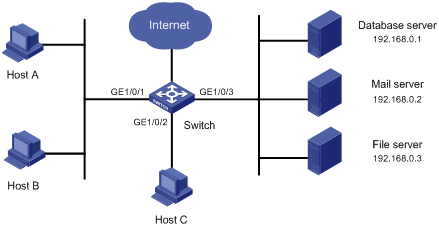
Figure 1-2 Network diagram for priority re-marking and queue scheduling configuration
Networking and Configuration Requirements
A company uses a switch (an S5500-EI switch in this example) for interconnection. As shown in Figure 1-2,
l Host A and Host B are connected to GigabitEthernet 1/0/1 of the switch.
l Host C is connected to GigabitEthernet 1/0/2 of the switch.
l The database server, the mail server, and the file server are connected to GigabitEthernet 1/0/3 of the switch.
Configure priority re-marking and queue scheduling to satisfy the following requirements:
l When Host C accesses the Internet or servers, the switch always processes the traffic from Host C preferentially.
Applicable Product Matrix
|
Product series |
Software version |
Hardware version |
|
S3610 Series Ethernet Switches |
Release 5301, Release 5303 |
All versions |
|
S5510 Series Ethernet Switches |
Release 5301, Release 5303 |
All versions |
|
S5500-SI Series Ethernet Switches |
Release 1207 |
All versions except S5500-20TP-SI |
|
Release 1301 |
S5500-20TP-SI |
|
|
S5500-EI Series Ethernet Switches |
Release 2102 |
All versions |
|
S7500E Series Ethernet Switches |
Release 6100, Release 6300 |
All versions |
Configuration Procedure
1) Configuration for the traffic from Host A and Host B
# Create an advanced ACL 3000 to match the packets with destination IP address 192.168.0.1.
<Switch> system-view
[Switch] acl number 3000
[Switch-acl-adv-3000] rule permit ip destination 192.168.0.1 0
[Switch-acl-adv-3000] quit
# Create an advanced ACL 3001 to match the packets with destination IP address 192.168.0.2.
<Switch> system-view
[Switch] acl number 3001
[Switch-acl-adv-3001] rule permit ip destination 192.168.0.2 0
[Switch-acl-adv-3001] quit
# Create an advanced ACL 3002 to match the packets with destination IP address 192.168.0.3.
<Switch> system-view
[Switch] acl number 3002
[Switch-acl-adv-3002] rule permit ip destination 192.168.0.3 0
[Switch-acl-adv-3002] quit
# Create a class classifier_dbserver and reference ACL 3000 in it.
[Switch] traffic classifier classifier_dbserver
[Switch-classifier-classifier_dbserver] if-match acl 3000
[Switch-classifier-classifier_dbserver] quit
# Create a class classifier_mserver and reference ACL 3001 in it.
[Switch] traffic classifier classifier_mserver
[Switch-classifier-classifier_mserver] if-match acl 3001
[Switch-classifier-classifier_mserver] quit
# Create a class classifier_fserver and reference ACL 3002 in it.
[Switch] traffic classifier classifier_fserver
[Switch-classifier-classifier_fserver] if-match acl 3002
[Switch-classifier-classifier_fserver] quit
# Create a traffic behavior behavior_dbserver and configure the action of setting the local precedence to 4 for it.
[Switch] traffic behavior behavior_dbserver
[Switch-behavior-behavior_dbserver] remark local-precedence 4
[Switch-behavior-behavior_dbserver] quit
# Create a traffic behavior behavior_mserver and configure the action of setting the local precedence to 3 for it.
[Switch] traffic behavior behavior_mserver
[Switch-behavior-behavior_mserver] remark local-precedence 3
[Switch-behavior-behavior_mserver] quit
# Create a traffic behavior behavior_fserver and configure the action of setting the local precedence to 2 for it.
[Switch] traffic behavior behavior_fserver
[Switch-behavior-behavior_fserver] remark local-precedence 2
[Switch-behavior-behavior_fserver] quit
# Create a policy policy_server and associate each class with the corresponding behavior in the policy.
[Switch] qos policy policy_server
[Switch-qospolicy-policy_server] classifier classifier_dbserver behavior behavior_dbserver
[Switch-qospolicy-policy_server] classifier classifier_mserver behavior behavior_mserver
[Switch-qospolicy-policy_server] classifier classifier_fserver behavior behavior_fserver
[Switch-qospolicy-policy_server] quit
# Apply the policy policy_server to the inbound direction of GigabitEthernet 1/0/1.
[Switch] interface GigabitEthernet 1/0/1
[Switch-GigabitEthernet1/0/1] qos apply policy policy_server inbound
[Switch-GigabitEthernet1/0/1] quit
# Enable strict priority (SP) queue scheduling on GigabitEthernet 1/0/3.
[Switch] interface GigabitEthernet 1/0/3
[Switch-GigabitEthernet1/0/3] qos sp
[Switch-GigabitEthernet1/0/3] quit
2) Configuration for the traffic from Host C
# Configure to trust the port priority on GigabitEthernet 1/0/2 and set the port priority of GigabitEthernet 1/0/2 to 5. Note that a port trusts its port priority by default.
[Switch] interface GigabitEthernet 1/0/2
[Switch-GigabitEthernet1/0/2] qos priority 5
Complete Configuration
#
traffic classifier classifier_fserver operator and
if-match acl 3002
traffic classifier classifier_dbserver operator and
if-match acl 3000
traffic classifier classifier_mserver operator and
if-match acl 3001
#
traffic behavior behavior_fserver
remark local-precedence 2
traffic behavior behavior_dbserver
remark local-precedence 4
traffic behavior behavior_mserver
remark local-precedence 3
#
qos policy policy_server
classifier classifier_dbserver behavior behavior_dbserver
classifier classifier_mserver behavior behavior_mserver
classifier classifier_fserver behavior behavior_fserver
#
acl number 3000
rule 0 permit ip destination 192.168.0.1 0
acl number 3001
rule 0 permit ip destination 192.168.0.2 0
acl number 3002
rule 0 permit ip destination 192.168.0.3 0
#
interface GigabitEthernet1/0/1
qos apply policy policy_server inbound
#
interface GigabitEthernet1/0/2
qos priority 5
#
interface GigabitEthernet1/0/3
qos sp
#
Configuration Guidelines
Note that:
l On the S5500-EI series, refer to Table 1-1 for the support for the actions in the inbound and outbound directions.
l On the S7500E series, refer to Table 1-2 for the support for the actions in the inbound and outbound directions.
l On an S5500-EI or S7500E series switch, if a received packet matches both the inbound policy and the outbound policy, the outbound policy applies if the action in the outbound policy conflicts with that in the inbound policy. For example, if the action in the inbound policy is setting the DSCP to 10 for a packet, and the action in the outbound policy is setting the DSCP to 40 for the same packet, the DSCP of the packet is 40 when it leaves the switch.
l Each port of an S5500-SI, S5500-EI, or S7500E series switch provides eight output queues. You can configure part of them to adopt SP queuing and the others to adopt weighted round robin (WRR) queuing as required. By assigning some queues on the port to the SP scheduling group and the others to the WRR scheduling group (that is, group 1), you can implement SP + WRR queue scheduling on the port. In this approach, packets in the SP scheduling group are scheduled preferentially, and only when the SP scheduling group is empty will the packets in the WRR scheduling group be scheduled. Queues in the SP scheduling group are scheduled by the SP queue scheduling algorithm. Queues in the WRR scheduling group are scheduled by WRR.
l Each port of an S3610 or S5510 series switch provides eight output queues. You can configure part of them to adopt SP queuing and the others to adopt WRR queuing as required. By assigning some queues on the port to the SP scheduling group and the others to the WRR scheduling groups, you can implement SP + WRR queue scheduling on the port. The three groups are scheduled in the descending order of their maximum queue IDs, that is, the group with the largest maximum queue ID is scheduled preferentially. For example, you can assign queue 5 through queue 7 to the SP scheduling group, queue 2 through queue 4 to WRR scheduling group 1, and queue 0 and queue 1 to WRR scheduling group 2. In this case, the maximum queue ID is 7 in the SP scheduling group, 4 in WRR scheduling group 1, and 1 in WRR scheduling group 2. Therefore, the switch will schedule the three groups in the order of the SP group, WRR group 1, and WRR group 2. When the previous group is empty, the next group can be scheduled.
l When configuring WRR or the combination of SP and WRR on the port of an S3610 or S5510 series switch, make sure that the IDs of the queues assigned to the same scheduling group are continuous.
l By default, all the output queues on the port of an S5500-SI or S5500-EI series switch adopt the WRR queue scheduling algorithm and the default weight values are 1, 2, 3, 4, 5, 9, 13, and 15 for queue 0 to queue 7.
l By default, all the output queues of the port of an S3610, S5510 or S7500E series switch adopt the SP queue scheduling algorithm.
l On the S3610 and the S5510 series switches, you can configure the qos wred enable command on a port or port group to configure weighted random early detection (WRED).
l Support for the keywords of the remark command varies by device model, as shown in Table 1-3.
Table 1-3 Support for the remark command
|
Product series |
Description |
|
S3610 Series Ethernet Switches |
remark dot1p, remark drop-precedence, remark dscp, remark ip-precedence, remark local-precedence, remark service-vlan-id |
|
S5510 Series Ethernet Switches |
remark dot1p, remark drop-precedence, remark dscp, remark ip-precedence, remark local-precedence, remark service-vlan-id |
|
S5500-SI Series Ethernet Switches |
remark dot1p, remark dscp, remark ip-precedence, remark local-precedence |
|
S5500-EI Series Ethernet Switches |
remark customer-vlan-id, remark dot1p, remark drop-precedence, remark dscp, remark ip-precedence, remark local-precedence, remark service-vlan-id |
|
S7500E Series Ethernet Switches |
remark customer-vlan-id, remark dot1p, remark drop-precedence, remark dscp, remark ip-precedence, remark local-precedence, remark service-vlan-id |
Configuring Priority Mapping and Queue Scheduling
Network Diagram
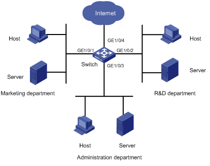
Figure 1-3 Network diagram for priority mapping and queue scheduling configuration
Networking and Configuration Requirements
A company uses a switch (an S5500-EI switch in this example) to interconnect all the departments. As shown in Figure 1-3,
l The marketing department is connected to GigabitEthernet 1/0/1 of the switch.
l The R&D department is connected to GigabitEthernet 1/0/2 of the switch.
l The administration department is connected to GigabitEthernet 1/0/3 of the switch.
l All packets from the devices in the three departments carry no VLAN tag.
Configure priority mapping and queue scheduling to satisfy the following requirements:
l Set the 802.1p priority of packets from the marketing department to 3 and assign these packets to queue 4 through priority mapping.
l Set the 802.1p priority of packets from the R&D department to 4 and assign these packets to queue 3 through priority mapping.
l Set the 802.1p priority of packets from the administration department to 5 and assign these packets to queue 6 through priority mapping.
Applicable Product Matrix
|
Product series |
Software version |
Hardware version |
|
S3610 Series Ethernet Switches |
Release 5301, Release 5303 |
All versions |
|
S5510 Series Ethernet Switches |
Release 5301, Release 5303 |
All versions |
|
S5500-SI Series Ethernet Switches |
Release 1207 |
All versions except S5500-20TP-SI |
|
Release 1301 |
S5500-20TP-SI |
|
|
S5500-EI Series Ethernet Switches |
Release 2102 |
All versions |
|
S7500E Series Ethernet Switches |
Release 6100, Release 6300 |
All versions |
Configuration Procedure
1) Configure port priorities
# Set the priority of GigabitEthernet 1/0/1 to 3.
<Switch> system-view
[Switch] interface GigabitEthernet 1/0/1
[Switch-GigabitEthernet1/0/1] qos priority 3
[Switch-GigabitEthernet1/0/1] quit
# Set the priority of GigabitEthernet 1/0/2 to 4.
[Switch] interface GigabitEthernet 1/0/2
[Switch-GigabitEthernet1/0/2] qos priority 4
[Switch-GigabitEthernet1/0/2] quit
# Set the priority of GigabitEthernet 1/0/3 to 5.
[Switch] interface GigabitEthernet 1/0/3
[Switch-GigabitEthernet1/0/3] qos priority 5
[Switch-GigabitEthernet1/0/3] quit
2) Configure priority mapping tables
# Configure the dot1p-lp mapping table to map 802.1p priority 3, 4, and 5 to local precedence 4, 3, and 6.
[Switch] qos map-table dot1p-lp
[Switch-maptbl-dot1p-lp] import 3 export 4
[Switch-maptbl-dot1p-lp] import 4 export 3
[Switch-maptbl-dot1p-lp] import 5 export 6
[Switch-maptbl-dot1p-lp] quit
3) Configure queue scheduling
# Enable WRR on GigabitEthernet 1/0/4, and set the weight values of queue 3, queue 4, and queue 6 to 5, 10, and 15.
[Switch] interface GigabitEthernet 1/0/4
[Switch-GigabitEthernet1/0/4] qos wrr 3 group 1 weight 5
[Switch-GigabitEthernet1/0/4] qos wrr 4 group 1 weight 10
[Switch-GigabitEthernet1/0/4] qos wrr 6 group 1 weight 15
Complete Configuration
#
qos map-table dot1p-lp
import 3 export 4
import 4 export 3
import 5 export 6
#
interface GigabitEthernet1/0/1
qos priority 3
#
interface GigabitEthernet1/0/2
qos priority 4
#
interface GigabitEthernet1/0/3
qos priority 5
#
interface GigabitEthernet1/0/4
qos wrr 3 group 1 weight 5
qos wrr 4 group 1 weight 10
qos wrr 6 group 1 weight 15
#
Configuration Guidelines
Support for queue scheduling varies by device model. For detailed information, refer to 102650 Configuration Guidelines.
When configuring priority mapping on an S3610 or S5510 series Ethernet switch, note that:
l The switch uses the priority of a port as the local precedence of untagged packets received on the port.
l Table 1-4 shows the default dot1p-lp and dot1p-dp mapping tables provided by the S3610 and the S5510 series.
Table 1-4 The default dot1p-lp and dot1p-dp mapping tables
|
Input value |
dot1p-lp mapping |
dot1p-dp mapping |
|
802.1p priority (dot1p) |
Local precedence (lp) |
Drop precedence (dp) |
|
0 |
2 |
0 |
|
1 |
0 |
0 |
|
2 |
1 |
0 |
|
3 |
3 |
0 |
|
4 |
4 |
0 |
|
5 |
5 |
0 |
|
6 |
6 |
0 |
|
7 |
7 |
0 |
l Table 1-5 shows the default dscp-lp, dscp-dp, dscp-dot1p, and dscp-dscp mapping tables provided by the S3610 and the S5510 series.
Table 1-5 The default dscp-lp, dscp-dp, dscp-dot1p, and dscp-dscp mapping tables
|
Input value |
dscp-lp mapping |
dscp-dp mapping |
dscp-dot1p mapping |
dscp-dscp mapping |
|
DSCP precedence |
Local precedence (lp) |
Drop precedence (dp) |
802.1p priority (dot1p) |
DSCP precedence |
|
0 to 7 |
0 |
0 |
0 |
0 |
|
8 to 15 |
1 |
0 |
1 |
8 |
|
16 to 23 |
2 |
0 |
2 |
16 |
|
24 to 31 |
3 |
0 |
3 |
24 |
|
32 to 39 |
4 |
0 |
4 |
32 |
|
40 to 47 |
5 |
0 |
5 |
40 |
|
48 to 55 |
6 |
0 |
6 |
48 |
|
56 to 63 |
7 |
0 |
7 |
56 |
![]()
l To use the dot1p-lp and dot1p-dp mapping tables to re-mark the local precedence and drop precedence for the packets received on a port, you must configure the port to trust the 802.1p priority of the received packets.
l To use the dscp-lp, dscp-dp, dscp-dot1p, or dscp-dscp mapping table for priority re-marking, you must reference it in the primap action of a traffic behavior.
When configuring priority mapping on the S5500-SI series Ethernet switches, note that:
l The switch uses the priority of a port as the 802.1p priority of the untagged packets received on the port, and then sets the local precedence for these packets based on the dot1p-lp mappings.
l The switch uses the 802.1p priority carried in tagged packets for dot1p-lp mapping to mark these packets with a local precedence.
l Table 1-6 shows the default dot1p-lp mapping table provided on the S5500-SI series.
Table 1-6 The default dot1p-lp mapping table
|
802.1p priority (dot1p) |
Local precedence (lp) |
|
0 |
2 |
|
1 |
0 |
|
2 |
1 |
|
3 |
3 |
|
4 |
4 |
|
5 |
5 |
|
6 |
6 |
|
7 |
7 |
![]()
The dot1p-lp mapping table provided on the S5500-SI series cannot be edited.
When configuring priority mapping on the S5500-EI/S7500E series Ethernet switches, note that:
l The S5500-EI and the S7500E series provide two priority trust modes: trusting the DSCP carried in packets, and trusting the 802.1p priority carried in packets.
l When the DSCP carried in packets is trusted, the carried DSCP is used in dscp-dot1p, dscp-dp, and dscp-dscp mapping to mark the packets with a new 802.1p priority, a drop precedence, and a DSCP. Then the marked 802.1p priority is used in dot1p-lp mapping to mark the packets with a local precedence.
l When the 802.1p priority carried in packets is trusted, if an untagged packet is received on the port, the switch uses the port priority as the 802.1p priority of the packet and uses the 802.1p priority in dot1p-lp mapping and dot1p-dp mapping to mark the packet with a local precedence and a drop precedence; if a tagged packet is received, the switch uses the 802.1p priority carried in the packet in dot1p-lp mapping and dot1p-dp mapping to mark the packet with a local precedence and a drop precedence.
l Table 1-7 and Table 1-8 show the default dot1p-lp, dot1p-dp, dscp-dot1p, dscp-dp, and dscp-dscp mapping tables provided on the S5500-EI/S7500E series.
Table 1-7 The default dot1p-lp and dot1p-dp mapping tables
|
Input value |
dot1p-lp mapping |
dot1p-dp mapping |
|
802.1p priority (dot1p) |
Local precedence (lp) |
Drop precedence (dp) |
|
0 |
2 |
0 |
|
1 |
0 |
0 |
|
2 |
1 |
0 |
|
3 |
3 |
0 |
|
4 |
4 |
0 |
|
5 |
5 |
0 |
|
6 |
6 |
0 |
|
7 |
7 |
0 |
Table 1-8 The default dscp-dp, dscp-dot1p, and dscp-dscp mapping tables
|
Input value |
dscp-dp mapping |
dscp-dot1p mapping |
dscp-dscp mapping |
|
DSCP precedence |
Drop precedence (dp) |
802.1p priority (dot1p) |
DSCP precedence |
|
0 to 7 |
0 |
0 |
0 |
|
8 to 15 |
0 |
1 |
8 |
|
16 to 23 |
0 |
2 |
16 |
|
24 to 31 |
0 |
3 |
24 |
|
32 to 39 |
0 |
4 |
32 |
|
40 to 47 |
0 |
5 |
40 |
|
48 to 55 |
0 |
6 |
48 |
|
56 to 63 |
0 |
7 |
56 |
![]()
In the dot1p-dp mapping table provided on the S5500-EI/S7500E series, no DSCP value can be mapped to drop precedence 1.
Configuring Traffic Mirroring and Redirecting Traffic to a Port
Network Diagram
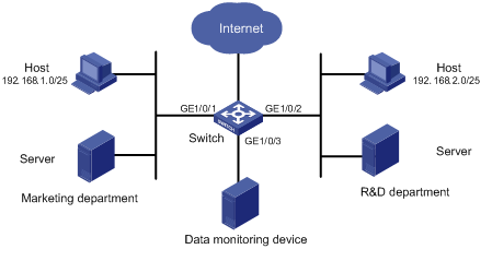
Figure 1-4 Network diagram for traffic redirecting and traffic mirroring configuration
Networking and Configuration Requirements
A company uses a switch (an S5500-EI switch in this example) to interconnect all the departments. As shown in Figure 1-4,
l The marketing department is connected to GigabitEthernet 1/0/1 of the switch. The IP address segment for the hosts of the marketing department is 192.168.1.0/25, and the hosts access the Internet through the Switch.
l The R&D department is connected to GigabitEthernet 1/0/2 of the switch. The IP address segment for the hosts of the R&D department is 192.168.2.0/25, and the hosts access the Internet through the Switch.
l The data monitoring device is connected to GigabitEthernet 1/0/3 of the switch.
Configure traffic redirecting and traffic mirroring to satisfy the following requirements:
l From 8:00 to 18:00 in working days, redirect the HTTP traffic from the Host in the marketing department to the Internet to the data monitoring device.
l From 8:00 to 18:00 in working days, redirect the HTTP traffic from the Host in the R&D department to the Internet to the data monitoring device.
Applicable Product Matrix
|
Product series |
Software version |
Hardware version |
|
S3610 Series Ethernet Switches |
Release 5301, Release 5303 |
All versions |
|
S5510 Series Ethernet Switches |
Release 5301, Release 5303 |
All versions |
|
S5500-SI Series Ethernet Switches |
Release 1207 |
All versions except S5500-20TP-SI |
|
Release 1301 |
S5500-20TP-SI |
|
|
S5500-EI Series Ethernet Switches |
Release 2102 |
All versions |
|
S7500E Series Ethernet Switches |
Release 6100, Release 6300 |
All versions |
Configuration Procedure
1) Define a time range for working days
# Create a time range trname covering the period from 8:00 to 18:00 during working days.
<Switch> system-view
[Switch] time-range trname 8:00 to 18:00 working-day
2) Configure a policy for the traffic of the marketing department
# Create basic ACL 2000 to match the traffic of the hosts in the marketing department during the specified time range.
[Switch] acl number 2000
[Switch-acl-basic-2000] rule permit source 192.168.1.0 0.0.0.127 time-range trname
[Switch-acl-basic-2000] quit
# Create a class classifier_market and reference ACL 2000 in it.
[Switch] traffic classifier classifier_market
[Switch-classifier-classifier_market] if-match acl 2000
[Switch-classifier-classifier_market] quit
# Create a traffic behavior behavior_market and configure the action of mirroring traffic to GigabitEthernet 1/0/3 for the traffic behavior.
[Switch] traffic behavior behavior_market
[Switch-behavior-behavior_market] mirror-to interface GigabitEthernet 1/0/3
[Switch-behavior-behavior_market] quit
# Create a policy policy_market and associate the class classifier_market with the traffic behavior behavior_market in the policy.
[Switch] qos policy policy_market
[Switch-qospolicy-policy_market] classifier classifier_market behavior behavior_market
[Switch-qospolicy-policy_market] quit
3) Configure a policy for the traffic of the R&D department
# Create basic ACL 2001 to match the traffic of the hosts in the R&D department during the specified time range.
[Switch] acl number 2001
[Switch-acl-basic-2001] rule permit source 192.168.2.0 0.0.0.127 time-range trname
[Switch-acl-basic-2001] quit
# Create a class classifier_rd and reference ACL 2001 in it.
[Switch] traffic classifier classifier_rd
[Switch-classifier-classifier_rd] if-match acl 2001
[Switch-classifier-classifier_rd] quit
# Create a traffic behavior behavior_rd and configure the action of redirecting traffic to GigabitEthernet 1/0/3 for the traffic behavior.
[Switch] traffic behavior behavior_rd
[Switch-behavior-behavior_rd] redirect interface GigabitEthernet 1/0/3
[Switch-behavior-behavior_rd] quit
# Create a policy policy_rd and associate the class classifier_rd with the traffic behavior behavior_rd in the policy.
[Switch] qos policy policy_rd
[Switch-qospolicy-policy_rd] classifier classifier_rd behavior behavior_rd
[Switch-qospolicy-policy_rd] quit
4) Apply QoS policies
# Apply the policy policy_market to the inbound direction of GigabitEthernet 1/0/1.
[Switch] interface GigabitEthernet 1/0/1
[Switch-GigabitEthernet1/0/1] qos apply policy policy_market inbound
[Switch-GigabitEthernet1/0/1] quit
# Apply the policy policy_rd to the inbound direction of GigabitEthernet 1/0/2.
[Switch] interface GigabitEthernet 1/0/2
[Switch-GigabitEthernet1/0/2] qos a policy policy_rd inbound
Complete Configuration
#
traffic classifier classifier_market operator and
if-match acl 2000
traffic classifier classifier_rd operator and
if-match acl 2001
#
traffic behavior behavior_market
mirror-to interface GigabitEthernet1/0/3
traffic behavior behavior_rd
redirect interface GigabitEthernet1/0/3
#
qos policy policy_market
classifier classifier_market behavior behavior_market
qos policy policy_rd
classifier classifier_rd behavior behavior_rd
#
time-range trname 08:00 to 18:00 working-day
#
acl number 2000
rule 0 permit source 192.168.1.0 0.0.0.127 time-range trname
acl number 2001
rule 0 permit source 192.168.2.0 0.0.0.127 time-range trname
#
interface GigabitEthernet1/0/1
qos apply policy policy_market inbound
#
interface GigabitEthernet1/0/2
qos apply policy policy_rd inbound
#
Configuration Guidelines
Note that:
l On the S5500-EI series switches, refer to Table 1-1 for the support for the actions in the inbound and outbound directions.
l On the S7500E series switches, refer to Table 1-2 for the support for the actions in the inbound and outbound directions.
l On the S5500-EI/S7500E series, if you want to apply the policy to the outbound direction, do not configure the mirror-to action together with any other actions in the same traffic behavior.
l On the S3610 and the S5510 series, the traffic mirroring destination port should not be the member port of an aggregation group.
l On the S3610 and the S5510 series, if you want to configure both traffic mirroring and local port mirroring, you must ensure that the traffic mirroring destination port and the monitor port for local port mirroring are the same one.
Redirecting Traffic to the Next Hop
Network Diagram
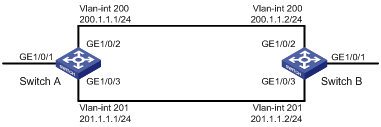
Figure 1-5 Network diagram for redirecting traffic to the next hop
Networking and Configuration Requirements
As shown in Figure 1-5,
l Switch A is dual-linked to Switch B. At the same time, Switch A and Switch B are each connected to other devices.
l GigabitEthernet 1/0/2 of Switch A and GigabitEthernet 1/0/2 of Switch B belong to VLAN 200.
l GigabitEthernet 1/0/3 of Switch A and GigabitEthernet 1/0/3 of Switch B belong to VLAN 201.
l On Switch A and Switch B, the IP address of VLAN interface 200 is 200.1.1.1, and the IP address of VLAN interface 201 is 201.1.1.1.
Configure the action of redirecting traffic to the next hop to implement policy routing as follows:
l On Switch A, packets with source IP address 2.1.1.1 received on GigabitEthernet 1/0/1 are forwarded to 200.1.1.2.
l The other packets received on GigabitEthernet 1/0/1 of Switch A are forwarded based on the routing table.
Applicable Product Matrix
|
Product series |
Software version |
Hardware version |
|
S3610 Series Ethernet Switches |
Release 5301, Release 5303 |
All versions |
|
S5510 Series Ethernet Switches |
Release 5301, Release 5303 |
All versions |
|
S5500-SI Series Ethernet Switches |
Release 1207 |
All versions except S5500-20TP-SI |
|
Release 1301 |
S5500-20TP-SI |
|
|
S5500-EI Series Ethernet Switches |
Release 2102 |
All versions |
|
S7500E Series Ethernet Switches |
Release 6100, Release 6300 |
All versions |
Configuration Procedure
l Configuration on Switch A
# Create basic ACL 2000 to match the packets with source IP address 2.1.1.1.
<Switch> system-view
[Switch] acl number 2000
[Switch-acl-basic-2000] rule permit source 2.1.1.1 0
[Switch-acl-basic-2000] quit
# Create basic ACL 2001 to match the packets with source IP address 2.1.1.2.
[Switch] acl number 2001
[Switch-acl-basic-2001] rule permit source 2.1.1.2 0
[Switch-acl-basic-2001] quit
# Create a class classifier_1 and reference ACL 2000 in it.
[Switch] traffic classifier classifier_1
[Switch-classifier-classifier_1] if-match acl 2000
[Switch-classifier-classifier_1] quit
# Create a traffic behavior behavior_1 and configure the action of redirecting traffic to the IP address 200.1.1.2 for it.
[Switch] traffic behavior behavior_1
[Switch-behavior-behavior_1] redirect next-hop 200.1.1.2
[Switch-behavior-behavior_1] quit
# Create a class classifier_2 and reference ACL 2001 in it.
[Switch] traffic classifier classifier_2
[Switch-classifier-classifier_2] if-match acl 2001
[Switch-classifier-classifier_2] quit
# Create a traffic behavior behavior_2 and configure the action of redirecting traffic to the IP address 200.1.1.2 for it.
[Switch] traffic behavior behavior_2
[Switch-behavior-behavior_2] redirect next-hop 201.1.1.2
[Switch-behavior-behavior_2] quit
# Create a policy policy, associate the class classifier_1 with the traffic behavior behavior_1, and associate the class classifier_2 with the traffic behavior behavior_2 in the policy.
[Switch] qos policy policy
[Switch-qospolicy-policy] classifier classifier_1 behavior behavior_1
[Switch-qospolicy-policy] classifier classifier_2 behavior behavior_2
[Switch-qospolicy-policy] quit
# Apply the policy policy to the inbound direction of GigabitEthernet 1/0/1.
[Switch] interface GigabitEthernet 1/0/1
[Switch-GigabitEthernet1/0/1] qos apply policy policy inbound
Complete Configuration
#
traffic classifier classifier_1 operator and
if-match acl 2000
traffic classifier classifier_2 operator and
if-match acl 2001
#
traffic behavior behavior_1
redirect next-hop 200.1.1.2
traffic behavior behavior_2
redirect next-hop 201.1.1.2
#
qos policy policy
classifier classifier_1 behavior behavior_1
classifier classifier_2 behavior behavior_2
#
acl number 2000
rule 0 permit source 2.1.1.1 0
acl number 2001
rule 0 permit source 2.1.1.2 0
#
interface GigabitEthernet1/0/1
qos apply policy policy inbound
#
Configuration Guidelines
Note that:
l On the S5500-EI series switches, refer to Table 1-1 for the support for the actions in the inbound and outbound directions.
l On the S7500E series switches, refer to Table 1-2 for the support for the actions in the inbound and outbound directions.
l You can configure policy routing as required. Different from the traditional destination-based routing mechanism, policy routing enables you to implement policies (based on the source address and other criteria) that make packets flexibly take different paths.
l Policy routing takes priority over generic routing, that is, packets are forwarded through policy routing preferentially. If no match is found, packets will be forwarded through generic routing.