- Table of Contents
-
- H3C Low-End and Mid-Range Ethernet Switches Configuration Examples(V1.01)
- 00-1Cover
- 01-Login Configuration Guide
- 02-VLAN Configuration Guide
- 03-GVRP Configuration Guide
- 04-Voice VLAN Configuration Guide
- 05-IP Addressing and Performance Configuration Guide
- 06-QinQ Configuration Guide
- 07-BPDU Tunnel Configuration Guide
- 08-VLAN Mapping Configuration Guide
- 09-MAC Address Table Management Configuration Guide
- 10-Link Aggregation Configuration Guide
- 11-IP Source Guard Configuration Guide
- 12-DLDP Configuration Guide
- 13-MSTP Configuration Guide
- 14-IPv4 Routing Configuration Guide
- 15-IPv6 Configuration Guide
- 16-IPv6 Routing Configuration Guide
- 17-IPv4 Multicast Configuration Guide
- 18-IPv6 Multicast Configuration Examples
- 19-802.1x Configuration Guide
- 20-AAA Configuration Guide
- 21-MAC Authentication Configuration Guide
- 22-Portal Configuration Guide
- 23-ARP Configuration Guide
- 24-DHCP Configuration Guide
- 25-ACL Configuration Guide
- 26-QoS Configuration Guide
- 27-Port Mirroring Configuration Guide
- 28-Cluster Management Configuration Guide
- 29-SNMP-RMON Configuration Guide
- 30-NTP Configuration Guide
- 31-FTP-TFTP Configuration Guide
- 32-UDP Helper Configuration Guide
- 33-Information Center Configuration Guide
- 34-DNS Configuration Guide
- 35-File System Management Configuration Guide
- 36-Remote Upgrade Configuration Guide
- 37-NQA Configuration Guide
- 38-VRRP Configuration Guide
- 39-SSH Configuration Guide
- 40-Port Security Configuration Guide
- 41-Port Isolation Configuration Guide
- 42-LLDP Configuration Guide
- 43-MCE Configuration Guide
- 44-PoE Configuration Guide
- 45-OAM Configuration Guide
- 46-Connectivity Fault Detection Configuration Guide
- 47-RRPP Configuration Guide
- 48-sFlow Configuration Guide
- 49-SSL-HTTPS Configuration Guide
- 50-PKI Configuration Guide
- 51-Track Configuration Guide
- 52-EPON-OLT Configuration Guide
- 53-Smart Link Configuration Guide
- 54-MPLS Configuration Guide
- Related Documents
-
| Title | Size | Download |
|---|---|---|
| 34-DNS Configuration Guide | 89.49 KB |
Table of Contents
Configuring Static Domain Name Resolution
Networking and Configuration Requirements
Configuring Dynamic Domain Name Resolution
Networking and Configuration Requirements
Networking and Configuration Requirements
Configuring Static Domain Name Resolution
The static domain name resolution means setting up mappings between domain names and IP addresses. IP addresses of the corresponding domain names can be found in the static domain resolution table when you use applications such as telnet.
Network diagram
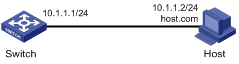
Figure 1-1 Network diagram for static domain name resolution
Networking and Configuration Requirements
Switch uses the static domain name resolution to access Host with IP address 10.1.1.2 through domain name host.com.
Applicable Product Matrix
|
Product series |
Software version |
Hardware version |
|
S3610 Series Ethernet Switches |
Release 5301 Release 5303 |
All versions |
|
S5510 Series Ethernet Switches |
Release 5301 Release 5303 |
All versions |
|
S5500-SI Series Ethernet Switches |
Release 1207 |
All versions except S5500-20TP-SI |
|
Release 1301 |
S5500-20TP-SI |
|
|
S5500-EI Series Ethernet Switches |
Release 2102 |
All versions |
|
S7500E Series Ethernet Switches |
Release 6100 Release 6300 |
All versions |
|
S3500-EA Series Ethernet Switches |
Release 5303 |
All versions |
Configuration procedure
# Configure a mapping between host name host.com and IP address 10.1.1.2.
<Sysname> system-view
[Sysname] ip host host.com 10.1.1.2
# Execute the ping host.com command to verify that Switch can use the static domain name resolution to get the IP address 10.1.1.2 corresponding to host.com.
[Sysname] ping host.com
PING host.com (10.1.1.2):
56 data bytes, press CTRL_C to break
Reply from 10.1.1.2: bytes=56 Sequence=1 ttl=128 time=2 ms
Reply from 10.1.1.2: bytes=56 Sequence=2 ttl=128 time=2 ms
Reply from 10.1.1.2: bytes=56 Sequence=3 ttl=128 time=2 ms
Reply from 10.1.1.2: bytes=56 Sequence=4 ttl=128 time=2 ms
Reply from 10.1.1.2: bytes=56 Sequence=5 ttl=128 time=2 ms
--- host.com ping statistics ---
5 packet(s) transmitted
5 packet(s) received
0.00% packet loss
round-trip min/avg/max = 2/2/2 ms
Complete Configuration
#
ip host host.com 10.1.1.2
#
Configuration Guidelines
Configuring Dynamic Domain Name Resolution
Domain Name System (DNS) is a distributed database used by TCP/IP applications to translate domain names into corresponding IP addresses. With DNS, you can use easy-to-remember domain names in some applications and let the DNS server translate them into correct IP addresses.
Network diagram
Figure 1-2 Network diagram for dynamic domain name resolution
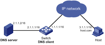
Networking and Configuration Requirements
l The IP address of the DNS server is 2.1.1.2/16 and the name suffix is com.
l Switch serves as a DNS client, and uses the dynamic domain name resolution and the suffix to access the host with the domain name host.com and the IP address 3.1.1.1/16.
Applicable Product Matrix
|
Product series |
Software version |
Hardware version |
|
S3610 Series Ethernet Switches |
Release 5301 Release 5303 |
All versions |
|
S5510 Series Ethernet Switches |
Release 5301 Release 5303 |
All versions |
|
S5500-SI Series Ethernet Switches |
Release 1207 |
All versions except S5500-20TP-SI |
|
Release 1301 |
S5500-20TP-SI |
|
|
S5500-EI Series Ethernet Switches |
Release 2102 |
All versions |
|
S7500E Series Ethernet Switches |
Release 6100 Release 6300 |
All versions |
|
S3500-EA Series Ethernet Switches |
Release 5303 |
All versions |
Configuration procedure
# Enable dynamic domain name resolution.
<Sysname> system-view
[Sysname] dns resolve
# Specify the DNS server 2.1.1.2.
[Sysname] dns server 2.1.1.2
# Configure com as the name suffix.
[Sysname] dns domain com
# Execute the ping host command on the device to verify that the communication between the device and the host is normal and that the corresponding destination IP address is 3.1.1.1.
[Sysname] ping host
Trying DNS resolve, press CTRL_C to break
Trying DNS server (2.1.1.2)
PING host.com (3.1.1.1):
56 data bytes, press CTRL_C to break
Reply from 3.1.1.1: bytes=56 Sequence=1 ttl=126 time=3 ms
Reply from 3.1.1.1: bytes=56 Sequence=2 ttl=126 time=1 ms
Reply from 3.1.1.1: bytes=56 Sequence=3 ttl=126 time=1 ms
Reply from 3.1.1.1: bytes=56 Sequence=4 ttl=126 time=1 ms
Reply from 3.1.1.1: bytes=56 Sequence=5 ttl=126 time=1 ms
--- host.com ping statistics ---
5 packet(s) transmitted
5 packet(s) received
0.00% packet loss
round-trip min/avg/max = 1/1/3 ms
Complete Configuration
#
dns resolve
dns server 2.1.1.2
dns domain com
#
Configuration Guidelines
l Before performing the above configuration, assume that the switch and the host are reachable to each other and the IP addresses of the interfaces are configured.
l The DNS client needs to cooperate with the DNS server to obtain a correct IP address through domain name resolution.
Configuring DNS Proxy
A DNS proxy forwards DNS requests and replies between DNS clients and a DNS server.
A DNS client sends a DNS request to the DNS proxy, which forwards the request to the designated DNS server, and conveys the reply from the DNS server to the client.
The DNS proxy simplifies network management. When the DNS server address is changed, you only need to change the configuration on the DNS proxy instead of on each DNS client.
Network diagram
Figure 1-3 Network diagram for DNS proxy
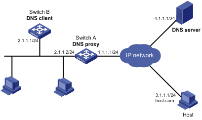
Networking and Configuration Requirements
l Specify Switch A as the DNS server of Switch B (the DNS client).
l Switch A acts as a DNS proxy. The IP address of the real DNS server is 4.1.1.1.
l Switch B implements domain name resolution through Switch A.
Applicable Product Matrix
|
Product series |
Software version |
Hardware version |
|
S5500-SI Series Ethernet Switches |
Release 1207 |
All versions except S5500-20TP-SI |
|
Release 1301 |
S5500-20TP-SI |
|
|
S5500-EI Series Ethernet Switches |
Release 2102 |
All versions |
|
S7500E Series Ethernet Switches |
Release 6100 Release 6300 |
All versions |
Configuration procedure
1) Configure the DNS proxy
# Specify the DNS server 4.1.1.1.
<SwitchA> system-view
[SwitchA] dns server 4.1.1.1
# Enable DNS proxy.
[SwitchA] dns proxy enable
2) Configure the DNS client
# Enable the domain name resolution function.
<SwitchB> system-view
[SwitchB] dns resolve
# Specify the DNS server 2.1.1.2.
[SwitchB] dns server 2.1.1.2
3) Configuration verification
# Execute the ping host.com command on Switch B to verify that the communication between the device and the host is normal and that the corresponding destination IP address is 3.1.1.1.
[SwitchB] ping host.com
Trying DNS resolve, press CTRL_C to break
Trying DNS server (2.1.1.2)
PING host.com (3.1.1.1):
56 data bytes, press CTRL_C to break
Reply from 3.1.1.1: bytes=56 Sequence=1 ttl=126 time=3 ms
Reply from 3.1.1.1: bytes=56 Sequence=2 ttl=126 time=1 ms
Reply from 3.1.1.1: bytes=56 Sequence=3 ttl=126 time=1 ms
Reply from 3.1.1.1: bytes=56 Sequence=4 ttl=126 time=1 ms
Reply from 3.1.1.1: bytes=56 Sequence=5 ttl=126 time=1 ms
--- host.com ping statistics ---
5 packet(s) transmitted
5 packet(s) received
0.00% packet loss
round-trip min/avg/max = 1/1/3 ms
Complete Configuration
l Configure Switch A (DNS proxy)
#
dns proxy enable
dns server 4.1.1.1
#
l Configure Switch B (DNS client)
#
dns resolve
dns server 2.1.1.2
#
Configuration Guidelines
l Before performing the above configuration, make sure that the switch and the host are reachable to each other and the IP addresses of the interfaces are configured.
l The DNS client needs to contact the DNS server to obtain a correct IP address through domain name resolution.