- Table of Contents
-
- H3C Low-End and Mid-Range Ethernet Switches Configuration Examples(V1.01)
- 00-1Cover
- 01-Login Configuration Guide
- 02-VLAN Configuration Guide
- 03-GVRP Configuration Guide
- 04-Voice VLAN Configuration Guide
- 05-IP Addressing and Performance Configuration Guide
- 06-QinQ Configuration Guide
- 07-BPDU Tunnel Configuration Guide
- 08-VLAN Mapping Configuration Guide
- 09-MAC Address Table Management Configuration Guide
- 10-Link Aggregation Configuration Guide
- 11-IP Source Guard Configuration Guide
- 12-DLDP Configuration Guide
- 13-MSTP Configuration Guide
- 14-IPv4 Routing Configuration Guide
- 15-IPv6 Configuration Guide
- 16-IPv6 Routing Configuration Guide
- 17-IPv4 Multicast Configuration Guide
- 18-IPv6 Multicast Configuration Examples
- 19-802.1x Configuration Guide
- 20-AAA Configuration Guide
- 21-MAC Authentication Configuration Guide
- 22-Portal Configuration Guide
- 23-ARP Configuration Guide
- 24-DHCP Configuration Guide
- 25-ACL Configuration Guide
- 26-QoS Configuration Guide
- 27-Port Mirroring Configuration Guide
- 28-Cluster Management Configuration Guide
- 29-SNMP-RMON Configuration Guide
- 30-NTP Configuration Guide
- 31-FTP-TFTP Configuration Guide
- 32-UDP Helper Configuration Guide
- 33-Information Center Configuration Guide
- 34-DNS Configuration Guide
- 35-File System Management Configuration Guide
- 36-Remote Upgrade Configuration Guide
- 37-NQA Configuration Guide
- 38-VRRP Configuration Guide
- 39-SSH Configuration Guide
- 40-Port Security Configuration Guide
- 41-Port Isolation Configuration Guide
- 42-LLDP Configuration Guide
- 43-MCE Configuration Guide
- 44-PoE Configuration Guide
- 45-OAM Configuration Guide
- 46-Connectivity Fault Detection Configuration Guide
- 47-RRPP Configuration Guide
- 48-sFlow Configuration Guide
- 49-SSL-HTTPS Configuration Guide
- 50-PKI Configuration Guide
- 51-Track Configuration Guide
- 52-EPON-OLT Configuration Guide
- 53-Smart Link Configuration Guide
- 54-MPLS Configuration Guide
- Related Documents
-
| Title | Size | Download |
|---|---|---|
| 27-Port Mirroring Configuration Guide | 167.02 KB |
Table of Contents
1 Port Mirroring Configuration Guide
Configuring Local Port Mirroring
Networking and Configuration Requirements
Configuring Remote Port Mirroring (with a Reflector Port)
Networking and Configuration Requirements
Configuring Remote Port Mirroring (with an Egress Port)
Networking and Configuration Requirements
Configuring Local Port Mirroring
Network Diagram
Figure 1-1 Network diagram for local port mirroring configuration
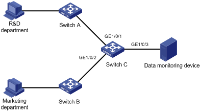
Networking and Configuration Requirements
The departments of a company communicate with each other through switches. The networking environment is described as follows:
l Switch C is an S5500-EI series Ethernet switch.
l The R&D department is connected to Switch C through port GigabitEthernet 1/0/1.
l The marketing department is connected to Switch C through port GigabitEthernet 1/0/2.
l The data monitoring device is connected to Switch C through port GigabitEthernet 1/0/3.
To monitor the bidirectional traffic of the R&D department and the marketing department on the data monitoring device, configure a local port mirroring group on Switch C as follows:
l Configure GigabitEthernet 1/0/1 and GigabitEthernet 1/0/2 as mirroring ports.
l Configure GigabitEthernet 1/0/3 as the monitor port.
Applicable Product Matrix
|
Product series |
Software version |
Hardware version |
|
S3610 Series Ethernet Switches |
Release 5301, Release 5303 |
All versions |
|
S5510 Series Ethernet Switches |
Release 5301, Release 5303 |
All versions |
|
S5500-SI Series Ethernet Switches |
Release 1207 |
All versions except S5500-20TP-SI |
|
Release 1301 |
S5500-20TP-SI |
|
|
S5500-EI Series Ethernet Switches |
Release 2102 |
All versions |
|
S7500E Series Ethernet Switches |
Release 6100, Release 6300 |
All versions |
Configuration Procedure
# Create a local mirroring group.
<SwitchC> system-view
[SwitchC] mirroring-group 1 local
# Configure ports GigabitEthernet 1/0/1 and GigabitEthernet 1/0/2 as mirroring ports and port GigabitEthernet 1/0/3 as the monitor port in the mirroring group.
[SwitchC] mirroring-group 1 mirroring-port GigabitEthernet 1/0/1 GigabitEthernet 1/0/2 both
[SwitchC] mirroring-group 1 monitor-port GigabitEthernet 1/0/3
# Display the configuration of all port mirroring groups.
[SwitchC] display mirroring-group all
mirroring-group 1:
type: local
status: active
mirroring port:
GigabitEthernet1/0/1 both
GigabitEthernet1/0/2 both
monitor port: GigabitEthernet1/0/3
Complete Configuration
#
mirroring-group 1 local
#
interface GigabitEthernet1/0/1
mirroring-group 1 mirroring-port both
#
interface GigabitEthernet1/0/2
mirroring-group 1 mirroring-port both
#
interface GigabitEthernet1/0/3
mirroring-group 1 monitor-port
#
Configuration Guidelines
When configuring local port mirroring, follow these guidelines:
l The packets mirrored to the monitor port may be VLAN tagged depending on your device model.
l Start the configuration with creating a local port mirroring group.
l For the local port mirroring group to take effect, assign a monitor port and at least one mirroring port to the group. These ports cannot be members of any other mirroring group and only one monitor port is allowed.
l To ensure normal operation of port mirroring, make sure that STP, RSTP, and MSTP are disabled on the monitor port.
l Use the monitor port only for port mirroring.
l On an S3610 or S5510 series Ethernet switch, only one local port mirroring group can be created.
l On an S3610 or S5510 series Ethernet switch, the monitor port must not be a link aggregation member port.
Configuring Remote Port Mirroring (with a Reflector Port)
Remote port mirroring is implemented through the cooperation of a remote source mirroring group and a remote destination mirroring group.
0 illustrates the implementation of remote port mirroring with a reflector port:
Figure 1-2 Remote port mirroring implementation (with a reflector port)
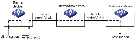
The functions of each device role are as following:
l Source device: The device where the mirroring ports are located. On it, you need to create a remote source mirroring group to hold the mirroring ports. The source device copies the packets passing through the mirroring ports, broadcasts the packets in the remote probe VLAN for remote mirroring through the reflector port, and transmits the packets to the next device, which could be an intermediate device (if any) or the destination device.
l Intermediate device: A device located in between the source device and the destination device. An intermediate device forwards mirrored packets to the next intermediate device (if any) or the destination device. You must ensure that the source device and the destination device can communicate at Layer 2 in the remote probe VLAN.
l Destination device: The device where the monitor port is located. On it, you must create the remote destination mirroring group. When receiving a packet, the destination device compares the VLAN ID carried in the packet with the ID of the probe VLAN configured in the remote destination mirroring group. If they are the same, the device forwards the packet to the monitoring device through the monitor port.
1.1.1 Network Diagram
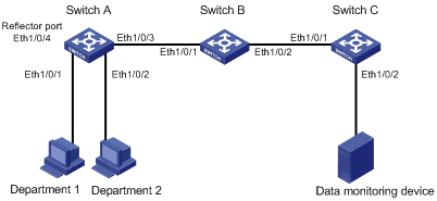
Figure 1-3 Network diagram for remote port mirroring configuration (with a reflector port)
Networking and Configuration Requirements
The departments of a company communicate with each other through switches. The networking environment is as follows:
l Switch A, Switch B, and Switch C are S3610 series Ethernet switches.
l Department 1 is connected to Ethernet 1/0/1 of Switch A.
l Department 2 is connected to Ethernet 1/0/2 of Switch A.
l Ethernet 1/0/3 of Switch A is connected to Ethernet 1/0/1 of Switch B.
l Ethernet 1/0/2 of Switch B is connected to Ethernet 1/0/1 of Switch C.
l Data monitoring device is connected to Ethernet 1/0/2 of Switch C.
The administrator wants to monitor the packets sent by Department 1 and 2.
Use the remote port mirroring function to meet the requirement. Perform the following configuration:
l Use Switch A as the source device, Switch B as the intermediate device, and Switch C as the destination device.
l On Switch A, create a remote source mirroring group, configure VLAN 2 as the remote probe VLAN, ports Ethernet 1/0/1 and Ethernet 1/0/2 as the mirroring ports, and port Ethernet 1/0/4 as the reflector port.
l Configure Ethernet 1/0/3 of Switch A, Ethernet 1/0/1 and Ethernet 1/0/2 of Switch B, and Ethernet 1/0/1 of Switch C as trunk ports, allowing packets of VLAN 2 to pass through.
l On Switch C, create a remote destination mirroring group, configure VLAN 2 as the remote probe VLAN, and configure Ethernet 1/0/2, which is connected with the data monitoring device, as the monitor port.
Applicable Product Matrix
|
Product series |
Software version |
Hardware version |
|
S3610 Series Ethernet Switches |
Release 5301, Release 5303 |
All versions |
|
S5510 Series Ethernet Switches |
Release 5301, Release 5303 |
All versions |
Configuration Procedure
1) Configure Switch A (the source device)
# Create remote source mirroring group 1.
<SwitchA> system-view
[SwitchA] mirroring-group 1 remote-source
# Create VLAN 2.
[SwitchA] vlan 2
[SwitchA-vlan2] quit
# Configure ports Ethernet 1/0/1 and Ethernet 1/0/2 as the mirroring ports, Ethernet 1/0/4 as the reflector port, and VLAN 2 as the remote probe VLAN in the remote source mirroring group.
[SwitchA] mirroring-group 1 remote-probe vlan 2
[SwitchA] mirroring-group 1 mirroring-port Ethernet 1/0/1 Ethernet 1/0/2 inbound
[SwitchA] mirroring-group 1 reflector-port Ethernet 1/0/4
# Configure port Ethernet 1/0/3 as a trunk port, allowing packets of VLAN 2 to pass through.
[SwitchA] interface Ethernet 1/0/3
[SwitchA-Ethernet1/0/3] port link-type trunk
[SwitchA-Ethernet1/0/3] port trunk permit vlan 2
2) Configure Switch B (the intermediate device)
# Configure port Ethernet 1/0/1 as a trunk port, allowing packets of VLAN 2 to pass through.
<SwitchB> system-view
[SwitchB] interface Ethernet 1/0/1
[SwitchB-Ethernet1/0/1] port link-type trunk
[SwitchB-Ethernet1/0/1] port trunk permit vlan 2
[SwitchB-Ethernet1/0/1] quit
# Configure port Ethernet 1/0/2 as a trunk port, allowing packets of VLAN 2 to pass through.
[SwitchB] interface Ethernet 1/0/2
[SwitchB-Ethernet1/0/2] port link-type trunk
[SwitchB-Ethernet1/0/2] port trunk permit vlan 2
3) Configure Switch C (the destination device)
# Configure port Ethernet 1/0/1 as a trunk port, allowing packets of VLAN 2 to pass through.
<SwitchC> system-view
[SwitchC] interface Ethernet 1/0/1
[SwitchC-Ethernet1/0/1] port link-type trunk
[SwitchC-Ethernet1/0/1] port trunk permit vlan 2
[SwitchC-Ethernet1/0/1] quit
# Create remote destination mirroring group 1.
[SwitchC] mirroring-group 1 remote-destination
# Create VLAN 2.
[SwitchC] vlan 2
[SwitchC-vlan2] quit
# Configure port Ethernet 1/0/2 as the monitor port and VLAN 2 as the remote probe VLAN in the remote destination mirroring group.
[SwitchC] mirroring-group 1 remote-probe vlan 2
[SwitchC] mirroring-group 1 monitor-port Ethernet 1/0/2
[SwitchC] interface Ethernet 1/0/2
[SwitchC-Ethernet1/0/2] port access vlan 2
Complete Configuration
Configuration on Switch A:
#
mirroring-group 1 remote-source
mirroring-group 1 remote-probe vlan 2
#
vlan 2
#
interface Ethernet1/0/1
mirroring-group 1 mirroring-port inbound
#
interface Ethernet1/0/2
mirroring-group 1 mirroring-port inbound
#
interface Ethernet1/0/3
port link-type trunk
port trunk permit vlan 1 to 2
#
interface Ethernet1/0/4
mirroring-group 1 reflector-port
#
Configuration on Switch B:
#
interface Ethernet1/0/1
port link-type trunk
port trunk permit vlan 1 to 2
#
interface Ethernet1/0/2
port link-type trunk
port trunk permit vlan 1 to 2
#
Configuration on Switch C:
#
mirroring-group 1 remote-destination
mirroring-group 1 remote-probe vlan 2
#
vlan 2
#
interface Ethernet1/0/1
port link-type trunk
port trunk permit vlan 1 to 2
#
interface Ethernet1/0/2
port access vlan 2
mirroring-group 1 monitor-port
#
Configuration Guidelines
Note the following when configuring the source device:
l The S3610 series and the S5510 series support only one remote source mirroring group.
l All ports in a remote source mirroring group must reside on the same device. A remote source mirroring group can have only one reflector port.
l A reflector port must be an access port and belong to the default VLAN. The port you will configure as a reflector port cannot be a member port in any mirroring group, a link aggregation group member port, or a QinQ-enabled port.
l You can configure a port as a reflector port only when the port is operating with the default duplex mode, port rate, and MDI setting. In addition, you cannot change these settings after the port is configured as a reflector port.
l To ensure normal operation of port mirroring, do not connect a cable to the reflector port, and make sure that STP, MSTP, RSTP, 802.1x, IGMP Snooping, static ARP, and MAC address learning are disabled on the reflector port.
l Only an existing static VLAN can be configured as a remote probe VLAN. To remove the VLAN configured as a remote probe VLAN, you need to remove the remote probe VLAN configuration first. Removing the remote probe VLAN can invalidate the remote source mirroring group.
l Use the remote probe VLAN only for remote port mirroring purpose.
l A VLAN can be the remote probe VLAN of only one remote source mirroring group.
Note the following when configuring the destination device:
l To implement remote port mirroring, you need to configure a remote destination mirroring group on the destination device.
l The port you will configure as a monitor port cannot be a member port of a mirroring group.
l To ensure the normal operation of port mirroring, make sure that STP, RSTP, and MSTP are disabled on the monitor port.
l Use the port configured as the monitor port only for port mirroring purpose.
l Only an existing static VLAN can be configured as a remote probe VLAN. To remove the VLAN configured as a remote probe VLAN, you need to remove the remote probe VLAN configuration first. Removing the remote probe VLAN can invalidate the remote destination mirroring group.
l A VLAN can be the remote probe VLAN of only one remote destination mirroring group.
l Use the remote probe VLAN only for remote port mirroring purpose.
Configuring Remote Port Mirroring (with an Egress Port)
0 illustrates the implementation of remote port mirroring with an egress port:
Figure 1-4 Remote port mirroring implementation (with an egress port)
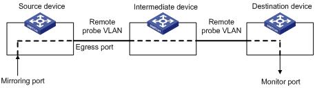
The functions of each device role are as following:
l Source device: The device where the mirroring ports are located. On it, you need to create a remote source mirroring group to hold the mirroring ports. The source device copies the packets passing through the mirroring ports, broadcasts the packets in the remote probe VLAN for remote mirroring through the egress port, and transmits the packets to the next device, which could be an intermediate device (if any) or the destination device.
l Intermediate device: A device located in between the source device and the destination device. An intermediate device forwards mirrored packets to the next intermediate device (if any) or the destination device. You must ensure that the source device and the destination device can communicate at Layer 2 in the remote probe VLAN.
l Destination device: The device where the monitor port is located. On it, you must create the remote destination mirroring group. When receiving a packet, the destination device compares the VLAN ID carried in the packet with the ID of the probe VLAN configured in the remote destination mirroring group. If they are the same, the device forwards the packet to the monitoring device through the monitor port.
1.1.1 Network Diagram
Figure 1-5 Network diagram for remote port mirroring configuration (with an egress port)
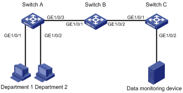
Networking and Configuration Requirements
The departments of a company communicate with each other through switches. The networking environment is as follows:
l Switch A, Switch B, and Switch C are S5500-EI series Ethernet switches.
l Department 1 is connected to GigabitEthernet 1/0/1 of Switch A.
l Department 2 is connected to GigabitEthernet 1/0/2 of Switch A.
l GigabitEthernet 1/0/3 of Switch A is connected to GigabitEthernet 1/0/1 of Switch B.
l GigabitEthernet 1/0/2 of Switch B is connected to GigabitEthernet 1/0/1 of Switch C.
l The data monitoring device is connected to Switch C through GigabitEthernet 1/0/2.
The administrator wants to monitor the packets sent by Department 1 and 2 through the data monitoring device.
Use the remote port mirroring function to meet the requirement. Perform the following configuration:
l Use Switch A as the source device, Switch B as the intermediate device, and Switch C as the destination device.
l On Switch A, create a remote source mirroring group, configure VLAN 2 as the remote probe VLAN, ports GigabitEthernet 1/0/1 and GigabitEthernet 1/0/2 as the mirroring ports, and port GigabitEthernet 1/0/3 as the egress port.
l Configure GigabitEthernet 1/0/3 of Switch A, GigabitEthernet 1/0/1 and GigabitEthernet 1/0/2 of Switch B, and GigabitEthernet 1/0/1 of Switch C as trunk ports, allowing packets of VLAN 2 to pass through.
l On Switch C, create a remote destination mirroring group, configure VLAN 2 as the remote probe VLAN, and configure GigabitEthernet 1/0/2, which is connected with the data monitoring device, as the monitor port.
Applicable Product Matrix
|
Product series |
Software version |
Hardware version |
|
S5500-EI Series Ethernet Switches |
Release 2102 |
All versions |
|
S7500E Series Ethernet Switches |
Release 6100, Release 6300 |
All versions |
Configuration Procedure
1) Configure Switch A (the source device)
# Create remote source mirroring group 1.
<SwitchA> system-view
[SwitchA] mirroring-group 1 remote-source
# Create VLAN 2.
[SwitchA] vlan 2
[SwitchA-vlan2] quit
# Configure ports GigabitEthernet 1/0/1 and GigabitEthernet 1/0/2 as the mirroring ports, and GigabitEthernet 1/0/3 as the egress port in the remote source mirroring group.
[SwitchA] mirroring-group 1 remote-probe vlan 2
[SwitchA] mirroring-group 1 mirroring-port GigabitEthernet 1/0/1 GigabitEthernet 1/0/2 inbound
[SwitchA] mirroring-group 1 monitor-egress GigabitEthernet 1/0/3
# Configure port GigabitEthernet 1/0/3 as a trunk port, allowing packets of VLAN 2 to pass through.
[SwitchA] interface GigabitEthernet 1/0/3
[SwitchA-GigabitEthernet1/0/3] port link-type trunk
[SwitchA-GigabitEthernet1/0/3] port trunk permit vlan 2
2) Configure Switch B (the intermediate device)
# Configure port GigabitEthernet 1/0/1 as a trunk port, allowing packets of VLAN 2 to pass through.
<SwitchB> system-view
[SwitchB] interface GigabitEthernet 1/0/1
[SwitchB-GigabitEthernet1/0/1] port link-type trunk
[SwitchB-GigabitEthernet1/0/1] port trunk permit vlan 2
[SwitchB-GigabitEthernet1/0/1] quit
# Configure port GigabitEthernet 1/0/2 as a trunk port, allowing packets of VLAN 2 to pass through.
[SwitchB] interface GigabitEthernet 1/0/2
[SwitchB-GigabitEthernet1/0/2] port link-type trunk
[SwitchB-GigabitEthernet1/0/2] port trunk permit vlan 2
3) Configure Switch C (the destination device)
# Configure port GigabitEthernet 1/0/1 as a trunk port, allowing packets of VLAN 2 to pass through.
<SwitchC> system-view
[SwitchC] interface GigabitEthernet 1/0/1
[SwitchC-GigabitEthernet1/0/1] port link-type trunk
[SwitchC-GigabitEthernet1/0/1] port trunk permit vlan 2
[SwitchC-GigabitEthernet1/0/1] quit
# Create remote destination mirroring group 1.
[SwitchC] mirroring-group 1 remote-destination
# Create VLAN 2.
[SwitchC] vlan 2
[SwitchC-vlan2] quit
# Configure port GigabitEthernet 1/0/2 as the monitor port and VLAN 2 as the remote probe VLAN in the remote destination mirroring group.
[SwitchC] mirroring-group 1 remote-probe vlan 2
[SwitchC] mirroring-group 1 monitor-port GigabitEthernet 1/0/2
[SwitchC] interface GigabitEthernet 1/0/2
[SwitchC-GigabitEthernet1/0/2] port access vlan 2
Complete Configuration
Configuration on Switch A:
#
mirroring-group 1 remote-source
mirroring-group 1 remote-probe vlan 2
#
vlan 2
#
interface GigabitEthernet1/0/1
mirroring-group 1 mirroring-port inbound
#
interface GigabitEthernet1/0/2
mirroring-group 1 mirroring-port inbound
#
interface GigabitEthernet1/0/3
port link-type trunk
port trunk permit vlan 1 to 2
mirroring-group 1 monitor-egress
#
Configuration on Switch B:
#
interface GigabitEthernet1/0/1
port link-type trunk
port trunk permit vlan 1 to 2
#
interface GigabitEthernet1/0/2
port link-type trunk
port trunk permit vlan 1 to 2
#
Configuration on Switch C:
#
mirroring-group 1 remote-destination
mirroring-group 1 remote-probe vlan 2
#
vlan 2
#
interface GigabitEthernet1/0/1
port link-type trunk
port trunk permit vlan 1 to 2
#
interface GigabitEthernet1/0/2
port access vlan 2
mirroring-group 1 monitor-port
#
Configuration Guidelines
Note the following when configuring the source device:
l To implement remote port mirroring, you need to configure a remote source mirroring group on the source device.
l All ports in a remote source mirroring group must reside on the same device. A remote source mirroring group can have only one egress port.
l The port you will configure as an egress port cannot be a member port of any mirroring group.
l To ensure normal operation of port mirroring, do not configure STP, MSTP, RSTP, 802.1x, IGMP Snooping, QinQ, static ARP, and MAC address learning on the egress port.
l Only an existing static VLAN can be configured as a remote probe VLAN. To remove the VLAN configured as a remote probe VLAN, you need to remove the remote probe VLAN configuration first. Removing the probe VLAN can invalidate the remote destination mirroring group.
l Use the remote probe VLAN only for remote port mirroring purpose.
l A VLAN can be the remote probe VLAN of only one remote source mirroring group.
Note the following when configuring the destination device:
l To implement remote port mirroring, you need to configure a remote destination mirroring group on the destination device.
l The port you will configure as a monitor port cannot be a member port of a mirroring group.
l To ensure normal operation of port mirroring, make sure that STP, RSTP, and MSTP are disabled on the monitor port.
l Use the monitor port only for port mirroring.
l Only an existing static VLAN can be configured as a remote probe VLAN. To remove the VLAN configured as a remote probe VLAN, you need to remove the remote probe VLAN configuration first. Removing the remote probe VLAN can invalidate the remote destination mirroring group.
l Use the remote probe VLAN only for remote port mirroring purpose.
l A VLAN can be the remote probe VLAN of only one remote destination mirroring group.