- Table of Contents
-
- H3C Low-End and Mid-Range Ethernet Switches Configuration Examples(V1.01)
- 00-1Cover
- 01-Login Configuration Guide
- 02-VLAN Configuration Guide
- 03-GVRP Configuration Guide
- 04-Voice VLAN Configuration Guide
- 05-IP Addressing and Performance Configuration Guide
- 06-QinQ Configuration Guide
- 07-BPDU Tunnel Configuration Guide
- 08-VLAN Mapping Configuration Guide
- 09-MAC Address Table Management Configuration Guide
- 10-Link Aggregation Configuration Guide
- 11-IP Source Guard Configuration Guide
- 12-DLDP Configuration Guide
- 13-MSTP Configuration Guide
- 14-IPv4 Routing Configuration Guide
- 15-IPv6 Configuration Guide
- 16-IPv6 Routing Configuration Guide
- 17-IPv4 Multicast Configuration Guide
- 18-IPv6 Multicast Configuration Examples
- 19-802.1x Configuration Guide
- 20-AAA Configuration Guide
- 21-MAC Authentication Configuration Guide
- 22-Portal Configuration Guide
- 23-ARP Configuration Guide
- 24-DHCP Configuration Guide
- 25-ACL Configuration Guide
- 26-QoS Configuration Guide
- 27-Port Mirroring Configuration Guide
- 28-Cluster Management Configuration Guide
- 29-SNMP-RMON Configuration Guide
- 30-NTP Configuration Guide
- 31-FTP-TFTP Configuration Guide
- 32-UDP Helper Configuration Guide
- 33-Information Center Configuration Guide
- 34-DNS Configuration Guide
- 35-File System Management Configuration Guide
- 36-Remote Upgrade Configuration Guide
- 37-NQA Configuration Guide
- 38-VRRP Configuration Guide
- 39-SSH Configuration Guide
- 40-Port Security Configuration Guide
- 41-Port Isolation Configuration Guide
- 42-LLDP Configuration Guide
- 43-MCE Configuration Guide
- 44-PoE Configuration Guide
- 45-OAM Configuration Guide
- 46-Connectivity Fault Detection Configuration Guide
- 47-RRPP Configuration Guide
- 48-sFlow Configuration Guide
- 49-SSL-HTTPS Configuration Guide
- 50-PKI Configuration Guide
- 51-Track Configuration Guide
- 52-EPON-OLT Configuration Guide
- 53-Smart Link Configuration Guide
- 54-MPLS Configuration Guide
- Related Documents
-
| Title | Size | Download |
|---|---|---|
| 29-SNMP-RMON Configuration Guide | 98.38 KB |
Configuring SNMPv2c to Monitor and Manage a Switch
Networking and Configuration Requirements
Configuring SNMPv3 to Monitor and Manage a Switch
Networking and Configuration Requirements
Networking and Configuration Requirements
Networking and Configuration Requirements
SNMP Overview
Simple Network Management Protocol (SNMP) offers a framework to monitor network devices through TCP/IP protocol suite. It provides a set of basic operations in monitoring and maintaining the Internet and has the following characteristics:
l Automatic network management: SNMP enables network administrators to search and modify information, find and diagnose network problems, plan for network growth, and generate reports on network nodes.
l SNMP shields the physical differences between various devices and thus realizes automatic management of products from different manufacturers. Offering only the basic set of functions, SNMP makes the management tasks independent of both the physical features of the managed devices and the underlying networking technology. Thus, SNMP achieves effective management of devices from different manufacturers, especially in small, high-speed and low cost network environments.
Configuring SNMPv2c to Monitor and Manage a Switch
Network Diagram
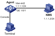
Figure 1-1 Network diagram for configuring SNMPv2c to monitor and manage a switch
Networking and Configuration Requirements
l The Network Management Station (NMS) connects to the agent, a switch, through an Ethernet.
l The IP address of the NMS is 1.1.1.2/24.
l The IP address of VLAN interface on the switch is 1.1.1.1/24.
l NMS monitors and manages Agent using SNMPv2c. Agent reports errors or faults to the NMS.
Applicable Product Matrix
|
Product series |
Software version |
Hardware version |
|
S3610 Series Ethernet Switches |
Release 5301, Release 5303 |
All versions |
|
S5510 Series Ethernet Switches |
Release 5301, Release 5303 |
All versions |
|
S5500-SI Series Ethernet Switches |
Release 1207 |
All versions except S5500-20TP-SI |
|
Release 1301 |
S5500-20TP-SI |
|
|
S5500-EI Series Ethernet Switches |
Release 2102 |
All versions |
|
S7500E Series Ethernet Switches |
Release 6100, Release 6300 |
All versions |
|
S3500-EA Series Ethernet Switches |
Release 5303 |
All versions |
Configuration Procedure
l Configure Agent
# Configure the SNMP basic information, including version and community name.
<Sysname> system-view
[Sysname] snmp-agent sys-info version v2c
[Sysname] snmp-agent community read public
[Sysname] snmp-agent community write private
# Configure VLAN-interface 2 (with the IP address of 1.1.1.1/24). Add the port GigabitEthernet 1/0/1 to VLAN 2.
[Sysname] vlan 2
[Sysname-vlan2] port GigabitEthernet 1/0/1
[Sysname-vlan2] quit
[Sysname] interface vlan-interface 2
[Sysname-Vlan-interface2] ip address 1.1.1.1 255.255.255.0
[Sysname-Vlan-interface2] quit
# Configure the contact person and physical location information of the switch.
[Sysname] snmp-agent sys-info version all
[Sysname] snmp-agent sys-info contact Mr.Chen-Tel:5651
[Sysname] snmp-agent sys-info location telephone-closet,3rd-floor
# Enable the sending of traps to the NMS with an IP address of 1.1.1.2/24, using public as the community name.
[Sysname] snmp-agent trap enable
[Sysname] snmp-agent target-host trap address udp-domain 1.1.1.2 udp-port 5000 params securityname public
l Configure SNMP NMS (refer to NMS manuals for detailed configurations)
#Select SNMPv2c; configure public as the read only community name, private as the read and write community name; specify 161 as the SNMP port number.
# In order to receive traps sent from Agent, set the number of inbound port for traps on the NMS to 5000, which is the same with that configured using the command line on Agent.
# Upon the above configurations, the NMS can monitor and manage the switch remotely; and the switch will send traps to the NMS in case of failures or errors.
Complete Configuration
#
interface Vlan-interface2
ip address 1.1.1.1 255.255.255.0
#
interface GigabitEthernet1/0/1
port access vlan 2
#
snmp-agent
snmp-agent local-engineid 800063A20300E0FC123456
snmp-agent community read public
snmp-agent community write private
snmp-agent sys-info contact Mr.Chen-Tel:5651
snmp-agent sys-info location telephone-closet,2rd-floor
snmp-agent sys-info version all
snmp-agent target-host trap address udp-domain 1.1.1.2 udp-port 5000 params securityname public
#
Configuration Guidelines
Follow these guidelines when configuring SNMPv2c to monitor and manage a switch:
1) The user can inquire and configure the device through the NMS (like Quidview), and refer to NMS manuals for detailed configurations.
2) The configurations on the agent and the NMS must match.
Configuring SNMPv3 to Monitor and Manage a Switch
Network Diagram
Figure 1-2 Network diagram for configuring SNMPv3 to monitor and manage a switch
Networking and Configuration Requirements
l The NMS connects to the agent, a switch, through an Ethernet.
l The IP address of the NMS is 1.1.1.2/24.
l The IP address of the VLAN interface on the switch is 1.1.1.1/24.
l NMS monitors and manages Agent using SNMPv3. Agent reports errors or faults to the NMS. The inbound port for traps on the NMS is 5000.
Applicable Product Matrix
|
Product series |
Software version |
Hardware version |
|
S3610 Series Ethernet Switches |
Release 5301, Release 5303 |
All versions |
|
S5510 Series Ethernet Switches |
Release 5301, Release 5303 |
All versions |
|
S5500-SI Series Ethernet Switches |
Release 1207 |
All versions except S5500-20TP-SI |
|
Release 1301 |
S5500-20TP-SI |
|
|
S5500-EI Series Ethernet Switches |
Release 2102 |
All versions |
|
S7500E Series Ethernet Switches |
Release 6100, Release 6300 |
All versions |
|
S3500-EA Series Ethernet Switches |
Release 5303 |
All versions |
Configuration Procedure
1) Configure Agent
# Configure the access right.
<Sysname> system-view
[Sysname] undo snmp-agent mib-view ViewDefault
[Sysname] snmp-agent mib-view included test interfaces
[Sysname] snmp-agent group v3 managev3group read-view test write-view test
[Sysname] snmp-agent usm-user v3 managev3user managev3group
# Configure the contact person and physical location information of the switch.
[Sysname] snmp-agent sys-info contact Mr.Chen-Tel:5651
[Sysname] snmp-agent sys-info location telephone-closet,2rd-floor
# Configure VLAN-interface 2 (with the IP address of 1.1.1.1/24). Add the port GigabitEthernet 1/0/1 to VLAN 2.
[Sysname] vlan 2
[Sysname-vlan2] port GigabitEthernet 1/0/1
[Sysname-vlan2] quit
[Sysname] interface vlan-interface 2
[Sysname-Vlan-interface2] ip address 1.1.1.1 255.255.255.0
[Sysname-Vlan-interface2] quit
# Configure the IP address of the VLAN-interface 2 as the source address of traps.
[Sysname] snmp-agent trap source Vlan-interface 2
# Enable sending of traps to the NMS with an IP address of 1.1.1.2/24, using public as the community name.
[Sysname] snmp-agent trap enable
[Sysname] snmp-agent target-host trap address udp-domain 1.1.1.2 udp-port 5000 params securityname public
2) Configure NMS
SNMPv3 uses authentication and privacy security model. In NMS, the user needs to specify username and security level, and based on that level, configure the authentication mode, authentication password, privacy mode, and privacy password. In addition, the timeout time and number of retries should also be configured. The user can inquire and configure the device through NMS, and refer to NMS manuals for detailed configurations.
Complete Configuration
#
interface Vlan-interface2
ip address 1.1.1.1 255.255.255.0
#
interface GigabitEthernet1/0/1
port access vlan 2
#
snmp-agent
snmp-agent local-engineid 800063A20300E0FC123456
snmp-agent sys-info contact Mr.Chen-Tel:5651
snmp-agent sys-info location telephone-closet,2rd-floor
snmp-agent sys-info version v3
snmp-agent group v3 managev3group read-view test write-view test
snmp-agent target-host trap address udp-domain 1.1.1.2 udp-port 5000 params securityname public
snmp-agent mib-view included test interfaces
snmp-agent usm-user v3 managev3user managev3group
snmp-agent trap source Vlan-interface2
Configuration Guidelines
Follow these guidelines when configuring SNMPv3 to monitor and manage a switch:
1) The user can inquire and configure the device through the NMS, and refer to NMS manuals for detailed configurations.
2) The configurations on the agent and the NMS must match.
Configuring SNMP Logging
Network Diagram
Figure 1-3 Network diagram for SNMP logging
Networking and Configuration Requirements
l The NMS connects to Agent, a switch, through an Ethernet.
l The IP address of the NMS is 1.1.1.2/2.
l The IP address of the VLAN interface on the switch is 1.1.1.1/24.
l Configure to output the logs of Get and Set operations of NMS on Agent to the terminal through the channel Console.
Applicable Product Matrix
|
Product series |
Software version |
Hardware version |
|
S3610 Series Ethernet Switches |
Release 5301, Release 5303 |
All versions |
|
S5510 Series Ethernet Switches |
Release 5301, Release 5303 |
All versions |
|
S5500-SI Series Ethernet Switches |
Release 1207 |
All versions except S5500-20TP-SI |
|
Release 1301 |
S5500-20TP-SI |
|
|
S5500-EI Series Ethernet Switches |
Release 2102 |
All versions |
|
S7500E Series Ethernet Switches |
Release 6100, Release 6300 |
All versions |
|
S3500-EA Series Ethernet Switches |
Release 5303 |
All versions |
Configuration Procedure
l Configure Agent
# Configure the SNMP basic information, including version and community name.
<Sysname> system-view
[Sysname] snmp-agent sys-info version all
[Sysname] snmp-agent community read public
[Sysname] snmp-agent community write private
# Configure VLAN-interface 2 (with the IP address of 1.1.1.1/24). Add the port GigabitEthernet 1/0/1 to VLAN 2.
[Sysname] vlan 2
[Sysname-vlan2] port GigabitEthernet 1/0/1
[Sysname-vlan2] quit
[Sysname] interface vlan-interface 2
[Sysname-Vlan-interface2] ip address 1.1.1.1 255.255.255.0
[Sysname-Vlan-interface2] quit
# Enable logging display on the terminal. (Optional. This function is enabled by default.)
<Sysname> terminal monitor
<Sysname> terminal logging
# Enable the information center to output the system information with the severity level equal to or higher than informational to the console port.
<Sysname> system-view
[Sysname] info-center source snmp channel console log level informational
# Enable SNMP logging on Agent to log the Get and Set operations of NMS.
[Sysname] snmp-agent log get-operation
[Sysname] snmp-agent log set-operation
l The following log information is displayed on the terminal when NMS performs the Get operation on Agent.
%Sep 9 02:49:40:566 2007 Sysname SNMP/6/GET:
seqNO = <10> srcIP = <1.1.1.2> op = <get> node = <sysName(1.3.6.1.2.1.1.5.0)> value=<>
l The following log information is displayed on the terminal when NMS performs the SET operation on Agent.
%Sep 9 02:59:42:576 2007 Sysname SNMP/6/SET:
seqNO = <11> srcIP = <1.1.1.2> op = <set> errorIndex = <0> errorStatus =<noError> node = <sysName(1.3.6.1.2.1.1.5.0)> value = <Sysname>
Complete Configuration
#
info-center source SNMP channel 0
#
interface Vlan-interface2
ip address 1.1.1.1 255.255.255.0
#
interface GigabitEthernet1/0/1
port access vlan 2
#
snmp-agent
snmp-agent local-engineid 800063A20300E0FC123456
snmp-agent community read public
snmp-agent community write private
snmp-agent log all
snmp-agent sys-info version all
Configuration Guidelines
Follow these guidelines when configuring SNMP logging:
1) The system information of the information center can be output to the terminal or to the log buffer. In this example, SNMP log is output to the terminal. For configuration of SNMP log output to other destinations, see the Information Center section in the Operation Manual of your product.
2) Successful output of logs to the terminal requires the Get and Set operations of NMS on Agent.
3) Logs occupy storage space of the device, thus affecting the performance of the device. Therefore, it is recommended to disable SNMP logging.
RMON Overview
Remote Monitoring (RMON) is implemented based on SNMP and is fully compatible with the existing SNMP framework without the need of any modification on SNMP.
RMON provides an efficient means of monitoring subnets and allows SNMP to monitor remote network devices in a more proactive and effective way. It reduces traffic between NMS and agent, facilitating large network management.
Configuring RMON
Network Diagram
Figure 2-1 Network diagram for RMON
Networking and Configuration Requirements
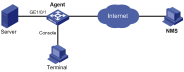
Agent is connected to a configuration terminal through its console port and to a remote NMS across the Internet.
Create an entry in the RMON Ethernet statistics table to gather statistics on GigabitEthernet 1/0/1, and logging is enabled after received bytes exceed the specified threshold.
Applicable Product Matrix
|
Product series |
Software version |
Hardware version |
|
S3610 Series Ethernet Switches |
Release 5301, Release 5303 |
All versions |
|
S5510 Series Ethernet Switches |
Release 5301, Release 5303 |
All versions |
|
S5500-SI Series Ethernet Switches |
Release 1207 |
All versions except S5500-20TP-SI |
|
Release 1301 |
S5500-20TP-SI |
|
|
S5500-EI Series Ethernet Switches |
Release 2102 |
All versions |
|
S7500E Series Ethernet Switches |
Release 6100, Release 6300 |
All versions |
|
S3500-EA Series Ethernet Switches |
Release 5303 |
All versions |
Configuration Procedure
# Configure RMON to gather statistics for interface GigabitEthernet 1/0/1.
<Sysname> system-view
[Sysname] interface GigabitEthernet 1/0/1
[Sysname-GigabitEthernet1/0/1] rmon statistics 1 owner user1-rmon
[Sysname-GigabitEthernet1/0/1] return
# Create an event to start logging after the event is triggered.
<Sysname> system-view
[Sysname] rmon event 1 log owner 1-rmon
# Configure an alarm group to sample received bytes on GigabitEthernet 1/0/1. When the received bytes exceed the upper limit or fall below the lower limit, logging is enabled.
[Sysname] rmon alarm 1 1.3.6.1.2.1.16.1.1.1.4.1 10 delta rising-threshold 1000 1 falling-threshold 100 1 owner 1-rmon
![]()
The node 1.3.6.1.2.1.16.1.1.1.4.1 indicates the statistics of received bytes for RMON statistics group 1, that is, the number of received bytes on GigabitEthernet 1/0/1.
Complete Configuration
#
interface GigabitEthernet1/0/1
rmon statistics 1 owner user1-rmon
#
rmon event 1 description null log owner 1-rmon
rmon alarm 1 1.3.6.1.2.1.16.1.1.1.4.1 10 delta rising-threshold 1000 1 falling-threshold 100 1 owner 1-rmon
Configuration Guidelines
N/A