- Table of Contents
-
- H3C Low-End and Mid-Range Ethernet Switches Configuration Examples(V1.01)
- 00-1Cover
- 01-Login Configuration Guide
- 02-VLAN Configuration Guide
- 03-GVRP Configuration Guide
- 04-Voice VLAN Configuration Guide
- 05-IP Addressing and Performance Configuration Guide
- 06-QinQ Configuration Guide
- 07-BPDU Tunnel Configuration Guide
- 08-VLAN Mapping Configuration Guide
- 09-MAC Address Table Management Configuration Guide
- 10-Link Aggregation Configuration Guide
- 11-IP Source Guard Configuration Guide
- 12-DLDP Configuration Guide
- 13-MSTP Configuration Guide
- 14-IPv4 Routing Configuration Guide
- 15-IPv6 Configuration Guide
- 16-IPv6 Routing Configuration Guide
- 17-IPv4 Multicast Configuration Guide
- 18-IPv6 Multicast Configuration Examples
- 19-802.1x Configuration Guide
- 20-AAA Configuration Guide
- 21-MAC Authentication Configuration Guide
- 22-Portal Configuration Guide
- 23-ARP Configuration Guide
- 24-DHCP Configuration Guide
- 25-ACL Configuration Guide
- 26-QoS Configuration Guide
- 27-Port Mirroring Configuration Guide
- 28-Cluster Management Configuration Guide
- 29-SNMP-RMON Configuration Guide
- 30-NTP Configuration Guide
- 31-FTP-TFTP Configuration Guide
- 32-UDP Helper Configuration Guide
- 33-Information Center Configuration Guide
- 34-DNS Configuration Guide
- 35-File System Management Configuration Guide
- 36-Remote Upgrade Configuration Guide
- 37-NQA Configuration Guide
- 38-VRRP Configuration Guide
- 39-SSH Configuration Guide
- 40-Port Security Configuration Guide
- 41-Port Isolation Configuration Guide
- 42-LLDP Configuration Guide
- 43-MCE Configuration Guide
- 44-PoE Configuration Guide
- 45-OAM Configuration Guide
- 46-Connectivity Fault Detection Configuration Guide
- 47-RRPP Configuration Guide
- 48-sFlow Configuration Guide
- 49-SSL-HTTPS Configuration Guide
- 50-PKI Configuration Guide
- 51-Track Configuration Guide
- 52-EPON-OLT Configuration Guide
- 53-Smart Link Configuration Guide
- 54-MPLS Configuration Guide
- Related Documents
-
| Title | Size | Download |
|---|---|---|
| 11-IP Source Guard Configuration Guide | 78.54 KB |
1 IP Source Guard Configuration Guide
Configuring Static Binding Entries
Network and Configuration Requirements
Networking and Configuration Requirements
IP Source Guard Overview
With the binding function of IP Source Guard, the device can filter packets forwarded by a port, preventing packets with illegal IP addresses or MAC addresses from traveling through the port. After receiving a packet, the port looks up the IP Source Guard binding entries and compares the key attributes of the packet against those in the binding entries. If a match is found, the port forwards the packet; otherwise, the port discards the packet.
IP Source Guard supports source IP address and source MAC address as the key attributes, and also supports the combinations (hereinafter referred to as binding entry) of port with source IP address, source MAC address, and source IP address plus source MAC address.
There are two binding methods: static binding and dynamic binding. Static binding means that binding entries are configured manually, and dynamic binding means that binding entries are generated by DHCP Snooping automatically. Besides, a binding entry is effective to only one port. That is, a binding entry for a port limits only the port, instead of other ports.
Configuring Static Binding Entries
Network Diagram
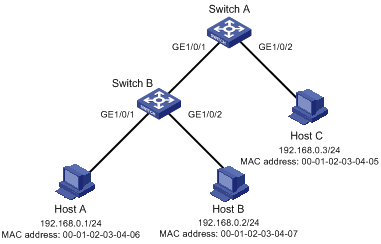
Figure 1-1 Network diagram for configuring static binding entries
Network and Configuration Requirements
As shown in Figure 1-1, Host A and Host B are connected to ports GigabitEthernet 1/0/1 and GigabitEthernet 1/0/2 of Switch B respectively, Host C is connected to port GigabitEthernet 1/0/2 of Switch A, and Switch B is connected to port GigabitEthernet 1/0/1 of Switch A.
Configure static binding entries on Switch A and Switch B to meet the following requirements:
l On port GigabitEthernet 1/0/2 of Switch A, only IP packets from Host C can pass.
l On port GigabitEthernet 1/0/1 of Switch A, only IP packets from Host A can pass.
l On port GigabitEthernet 1/0/1 of Switch B, only IP packets from Host A can pass.
l On port GigabitEthernet 1/0/2 of Switch B, only IP packets from Host B can pass.
Applicable Product Matrix
|
Software version |
Hardware version |
|
|
S3610 Series Ethernet Switches |
Release 5301 Release 5303 |
All versions |
|
S5510 Series Ethernet Switches |
Release 5301 Release 5303 |
All versions |
|
S5500-EI Series Ethernet Switches |
Release 2102 |
All versions |
|
S7500E Series Ethernet Switches |
Release 6100 Release 6300 |
All versions |
|
S3500-EA Series Ethernet Switches |
Release 5303 |
All versions |
Configuration Procedure
1) Configure Switch A
# Configure the IP addresses of the interfaces (omitted).
# Configure port GigabitEthernet 1/0/2 of Switch A to allow only IP packets with the source MAC address of 00-01-02-03-04-05 and the source IP address of 192.168.0.3 to pass.
<SwitchA> system-view
[SwitchA] interface gigabitethernet 1/0/2
[SwitchA-GigabitEthernet1/0/2] user-bind ip-address 192.168.0.3 mac-address 0001-0203-0405
[SwitchA-GigabitEthernet1/0/2] quit
# Configure port GigabitEthernet 1/0/1 of Switch A to allow only IP packets with the source MAC address of 00-01-02-03-04-06 and the source IP address of 192.168.0.1 to pass.
[SwitchA] interface gigabitethernet 1/0/1
[SwitchA-GigabitEthernet1/0/1] user-bind ip-address 192.168.0.1 mac-address 0001-0203-0406
# Configure the IP addresses of the interfaces (omitted).
# Configure port GigabitEthernet 1/0/1 of Switch B to allow only IP packets with the source MAC address of 00-01-02-03-04-06 and the source IP address of 192.168.0.1 to pass.
<SwitchB> system-view
[SwitchB] interface gigabitethernet 1/0/1
[SwitchB-GigabitEthernet1/0/1] user-bind ip-address 192.168.0.1 mac-address 0001-0203-0406
[SwitchA-GigabitEthernet1/0/1] quit
# Configure port GigabitEthernet 1/0/2 of Switch B to allow only IP packets with the source MAC address of 00-01-02-03-04-07 and the source IP address of 192.168.0.2 to pass.
[SwitchB] interface gigabitethernet 1/0/2
[SwitchB-GigabitEthernet1/0/2] user-bind ip-address 192.168.0.2 mac-address 0001-0203-0407
Complete Configuration
l SwitchA
#
interface GigabitEthernet1/0/2
user-bind ip-address 192.168.0.3 mac-address 0001-0203-0405
#
interface GigabitEthernet1/0/1
user-bind ip-address 192.168.0.1 mac-address 0001-0203-0406
l SwitchB
#
interface GigabitEthernet1/0/1
user-bind ip-address 192.168.0.1 mac-address 0001-0203-0406
#
interface GigabitEthernet1/0/2
user-bind ip-address 192.168.0.2 mac-address 0001-0203-0407
Configuration Guidelines
None
Configuring Dynamic Binding
Network Diagram
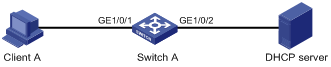
Figure 1-2 Network diagram for configuring dynamic binding
Networking and Configuration Requirements
Switch A connects to Client A and the DHCP server through ports GigabitEthernet 1/0/1 and GigabitEthernet 1/0/2 respectively. DHCP snooping is enabled on Switch A.
Detailed requirements are as follows:
l Client A (with the MAC address of 00-01-02-03-04-06) obtains an IP address through the DHCP server.
l On Switch A, create a DHCP snooping entry for Client A.
l On port GigabitEthernet 1/0/1 of Switch A, enable dynamic binding to prevent packets with forged IP addresses to attack the server.
Applicable Product Matrix
|
Product series |
Software version |
Hardware version |
|
S3610 Series Ethernet Switches |
Release 5301 Release 5303 |
All versions |
|
S5510 Series Ethernet Switches |
Release 5301 Release 5303 |
All versions |
|
S5500-EI Series Ethernet Switches |
Release 2102 |
All versions |
|
S7500E Series Ethernet Switches |
Release 6100 Release 6300 |
All versions |
|
S3500-EA Series Ethernet Switches |
Release 5303 |
All versions |
Configuration Procedure
1) Configure Switch A
# Configure dynamic binding on port GigabitEthernet 1/0/1.
<SwitchA> system-view
[SwitchA] interface GigabitEthernet1/0/1
[SwitchA-GigabitEthernet1/0/1] ip check source ip-address mac-address
[SwitchA-GigabitEthernet1/0/1] quit
# Enable DHCP snooping.
[SwitchA] dhcp-snooping
# Configure the port connecting to the DHCP server (GigabitEthernet 1/0/2) as a trusted port.
[SwitchA] interface GigabitEthernet1/0/2
[SwitchA-GigabitEthernet1/0/2] dhcp-snooping trust
[SwitchA-GigabitEthernet1/0/2] return
2) Verify the configuration
# Display the dynamic binding entries that port GigabitEthernet 1/0/1 has obtained from DHCP snooping.
<SwitchA> display ip check source
The following user address bindings have been configured:
MAC IP Vlan Port Status
0001-0203-0406 192.168.0.1 1 GigabitEthernet1/0/1 DHCP-SNP
-----------------1 binding entries queried, 1 listed------------------
# Display the dynamic DHCP snooping entries to check whether they are consistent with the dynamic binding entries that port GigabitEthernet 1/0/1 has obtained.
<SwitchA> display dhcp-snooping
DHCP Snooping is enabled.
The client binding table for all untrusted ports.
Type : D--Dynamic , S--Static
Type IP Address MAC Address Lease VLAN Interface
==== =============== ============== ============ ==== =================
D 192.168.0.1 0001-0203-0406 86335 1 GigabitEthernet1/0/1
As you see, after being configured with the dynamic binding function, port GigabitEthernet 1/0/1 has obtained the dynamic entries generated by DHCP snooping.
Complete Configuration
#
dhcp-snooping
#
interface GigabitEthernet1/0/1
ip check source ip-address mac-address
#
interface GigabitEthernet1/0/2
dhcp-snooping trust
Configuration Guidelines
1) Enabling IP source guard on a port is mutually exclusive with adding the port to an aggregation group.
2) If you configure both a QoS policy and the IP source guard feature on a port, the system will adopt the flow behaviors defined in the QoS policy.