- Table of Contents
-
- H3C Low-End and Mid-Range Ethernet Switches Configuration Examples(V1.01)
- 00-1Cover
- 01-Login Configuration Guide
- 02-VLAN Configuration Guide
- 03-GVRP Configuration Guide
- 04-Voice VLAN Configuration Guide
- 05-IP Addressing and Performance Configuration Guide
- 06-QinQ Configuration Guide
- 07-BPDU Tunnel Configuration Guide
- 08-VLAN Mapping Configuration Guide
- 09-MAC Address Table Management Configuration Guide
- 10-Link Aggregation Configuration Guide
- 11-IP Source Guard Configuration Guide
- 12-DLDP Configuration Guide
- 13-MSTP Configuration Guide
- 14-IPv4 Routing Configuration Guide
- 15-IPv6 Configuration Guide
- 16-IPv6 Routing Configuration Guide
- 17-IPv4 Multicast Configuration Guide
- 18-IPv6 Multicast Configuration Examples
- 19-802.1x Configuration Guide
- 20-AAA Configuration Guide
- 21-MAC Authentication Configuration Guide
- 22-Portal Configuration Guide
- 23-ARP Configuration Guide
- 24-DHCP Configuration Guide
- 25-ACL Configuration Guide
- 26-QoS Configuration Guide
- 27-Port Mirroring Configuration Guide
- 28-Cluster Management Configuration Guide
- 29-SNMP-RMON Configuration Guide
- 30-NTP Configuration Guide
- 31-FTP-TFTP Configuration Guide
- 32-UDP Helper Configuration Guide
- 33-Information Center Configuration Guide
- 34-DNS Configuration Guide
- 35-File System Management Configuration Guide
- 36-Remote Upgrade Configuration Guide
- 37-NQA Configuration Guide
- 38-VRRP Configuration Guide
- 39-SSH Configuration Guide
- 40-Port Security Configuration Guide
- 41-Port Isolation Configuration Guide
- 42-LLDP Configuration Guide
- 43-MCE Configuration Guide
- 44-PoE Configuration Guide
- 45-OAM Configuration Guide
- 46-Connectivity Fault Detection Configuration Guide
- 47-RRPP Configuration Guide
- 48-sFlow Configuration Guide
- 49-SSL-HTTPS Configuration Guide
- 50-PKI Configuration Guide
- 51-Track Configuration Guide
- 52-EPON-OLT Configuration Guide
- 53-Smart Link Configuration Guide
- 54-MPLS Configuration Guide
- Related Documents
-
| Title | Size | Download |
|---|---|---|
| 28-Cluster Management Configuration Guide | 85.67 KB |
Table of Contents
1 Cluster Management Configuration Guide
Configuring Cluster Management
Networking and Configuration Requirements
Configuring Cluster Management
Cluster management is implemented through Huawei Group Management Protocol version 2 (HGMPv2). By employing HGMPv2, a network administrator can manage multiple switches using the public IP address of one switch in a cluster. The switch that is configured with a public address and performs the management function is known as the management device; and other managed switches are called member devices, which are managed and maintained by the management device. The management device and member devices together form a cluster.
In a complex network environment, a network administrator uses HGMP to manage switches inside the network remotely, which is timesaving and easy to operate.
The network administrator can manage member devices through the management device only by performing the following operations:
l Create a cluster on the management device
l Enable Neighbor Discovery Protocol (NDP) and Neighbor Topology Discovery Protocol (NTDP) on member switches
l Enable HGMP
Network Diagram
Figure 1-1 Network diagram for HGMP
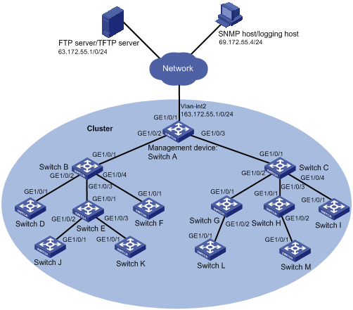
Networking and Configuration Requirements
l 13 switches form a cluster
l Switch A serves as the management device, and the other switches are the member devices
l The management VLAN of the cluster is VLAN 10
l The IP address of the management switch is 163.172.55.1
l The IP address of the TFTP server is 63.172.55.1
l The IP address of the SNMP network management (NM) host is 69.172.55.4
l All the devices in the cluster use the same FTP server and SNMP host.
Management device:
l Port GigabitEthernet 1/0/1 belongs to VLAN 2, whose interface IP address is 163.172.55.1
l The management device connects to two member devices through ports GigabitEthernet 1/0/2 and GigabitEthernet 1/0/3 respectively.
Member devices:
l Switch B (member device) connects with Switch D, E and F through ports GigabitEthernet 1/0/2, GigabitEthernet 1/0/3 and GigabitEthernet 1/0/4 respectively
l Switch C (member device) connects with Switch G, H and I through ports GigabitEthernet 1/0/2, GigabitEthernet 1/0/3 and GigabitEthernet 1/0/4 respectively.
l Switch E (member device) connects with Switches J and K through ports GigabitEthernet 1/0/2 and GigabitEthernet 1/0/3 respectively
![]()
l Switches A, B and C are usually low-end Ethernet switches, like S5500-SI series, and S5500-EI series.
l Switches D, E and F are usually low-end Ethernet switches, like S3610 series, and S5500 series.
Applicable Product Matrix
|
Product series |
Software version |
Hardware version |
|
S3610 Series Ethernet Switches |
Release 5301, Release 5303 |
All versions |
|
S5510 Series Ethernet Switches |
Release 5301, Release 5303 |
All versions |
|
S5500-SI Series Ethernet Switches |
Release 1207 |
All versions except S5500-20TP-SI |
|
Release 1301 |
S5500-20TP-SI |
|
|
S5500-EI Series Ethernet Switches |
Release 2102 |
All versions |
Configuration Procedure
1) Configure a member device (taking Switch B as an example)
# Enable NDP and NTDP on Switch B
<Sysname> system-view
[Sysname] ndp enable
[Sysname] ntdp enable
# Enable NDP and NTDP for ports GigabitEthernet 1/0/1, GigabitEthernet 1/0/2, GigabitEthernet 1/0/3, and GigabitEthernet 1/0/4.
[Sysname] interface GigabitEthernet 1/0/1
[Sysname-GigabitEthernet1/0/1] ndp enable
[Sysname-GigabitEthernet1/0/1] ntdp enable
[Sysname-GigabitEthernet1/0/1] quit
[Sysname] interface GigabitEthernet 1/0/2
[Sysname-GigabitEthernet1/0/2] ndp enable
[Sysname-GigabitEthernet1/0/2] ntdp enable
[Sysname-GigabitEthernet1/0/2] quit
[Sysname] interface GigabitEthernet 1/0/3
[Sysname-GigabitEthernet1/0/3] ndp enable
[Sysname-GigabitEthernet1/0/3] ntdp enable
[Sysname-GigabitEthernet1/0/3] quit
[Sysname] interface GigabitEthernet 1/0/4
[Sysname-GigabitEthernet1/0/4] ndp enable
[Sysname-GigabitEthernet1/0/4] ntdp enable
[Sysname-GigabitEthernet1/0/4] quit
![]()
l NDP and NTDP functions should be enabled for member switch ports connecting with the devices in the cluster.
l The management device may collect topology information of a device that does not need to join the cluster and add this device into the cluster. To avoid this, you are recommended to disable NDP on the port which connects with this device.
l The management device may collect topology information of a device that does not need to join the cluster and add this device into the cluster. To avoid this, you are recommended to disable NTDP on the port which connects with this device.
2) Configure the management device
# Enable the cluster function.
[Sysname] cluster enable
# Disable NDP on the uplink port GigabitEthernet 1/0/1.
<Sysname> system-view
[Sysname] ndp enable
[Sysname] undo ndp enable intferface GigabitEthernet 1/0/1
# Enable NDP for ports GigabitEthernet 1/0/2 and GigabitEthernet 1/0/3.
[Sysname] interface GigabitEthernet 1/0/2
[Sysname-GigabitEthernet1/0/2] ndp enable
[Sysname-GigabitEthernet1/0/2] quit
[Sysname] interface GigabitEthernet 1/0/3
[Sysname-GigabitEthernet1/0/3] ndp enable
[Sysname-GigabitEthernet1/0/3] quit
# Set the period for the receiving device to keep NDP packets to 300 seconds.
[Sysname] ndp timer aging 300
# Set the interval to send NDP packets to 100 seconds.
[Sysname] ndp timer hello 100
# Enable NTDP on the device and for ports GigabitEthernet 1/0/2 and GigabitEthernet 1/0/3.
[Sysname] ntdp enable
[Sysname] interface GigabitEthernet 1/0/2
[Sysname-GigabitEthernet1/0/2] ntdp enable
[Sysname-GigabitEthernet1/0/2] quit
[Sysname] interface GigabitEthernet 1/0/3
[Sysname-GigabitEthernet1/0/3] ntdp enable
[Sysname-GigabitEthernet1/0/3] quit
# Configure the hop count to collect topology as 2.
[Sysname] ntdp hop 2
# Configure the delay time for topology-collection request packets to be forwarded on member devices as 180 ms.
[Sysname] ntdp timer hop-delay 180
# Configure the delay time for topology-collection request packets to be forwarded through the ports of member devices as 20 ms.
[Sysname] ntdp timer port-delay 20
# Configure the interval to collect topology information as 3 minutes.
[Sysname] ntdp timer 3
# Configure the management VLAN of the cluster as VLAN 10.
[Switch] vlan 10
[Switch-vlan10] quit
[Switch] management-vlan 10
# Configure the port connecting the management device to candidate devices as a trunk port and allow packets from the management VLAN to pass.
[Switch] interface GigabitEthernet 1/0/1
[Switch-GigabitEthernet1/0/1] port link-type trunk
[Switch-GigabitEthernet1/0/1] port trunk permit vlan 10
[Switch-GigabitEthernet1/0/1] quit
[Switch] interface GigabitEthernet 1/0/3
[Switch-GigabitEthernet1/0/3] port link-type trunk
[Switch-GigabitEthernet1/0/3] port trunk permit vlan 10
[Switch-GigabitEthernet1/0/3] quit
# Enable the cluster function.
[Sysname] cluster enable
# Enter cluster view.
[Sysname] cluster
[Sysname-cluster]
# Configure an IP address pool for the cluster. The IP address pool contains 14 IP addresses, starting from 172.16.0.1.
[Sysname-cluster] ip-pool 172.16.0.1 255.255.255.240
# Specify a name for the cluster and create the cluster.
[Sysname-cluster] build aaa
[aaa_0.Sysname-cluster]
# Enable mangement VLAN auto-negotiation.
[aabbcc_0.Sysname-cluster] management-vlan synchronization enable
# Set the holdtime of the member device information to 100 seconds.
[aaa_0.Sysname-cluster] holdtime 100
# Set the interval to send handshake packets to 10 seconds.
[aaa_0.Sysname-cluster] timer 10
# Configure the FTP Server, TFTP Server and SNMP host for the cluster.
[aaa_0.Sysname-cluster] tftp-server 63.172.55.1
[aaa_0.Sysname-cluster] snmp-host 69.172.55.4
3) Operations on the cluster members
Perform the following operations after the management device adds the connected device into the cluster.
# The member device downloads the file aaa.txt from the TFTP server of the cluster.
<aaa_1.Sysname> tftp cluster get aaa.txt
# The member device uploads the file bbb.txt to the TFTP server of the cluster.
<aaa_1.Sysname> tftp cluster put bbb.txt
Complete Configuration
Configuration on switch A
#
ntdp hop 2
ntdp timer port-delay 20
ntdp timer hop-delay 180
ntdp timer 3
#
ndp timer hello 100
ndp timer aging 300
#
cluster
ip-pool 172.16.0.1 255.255.255.248
build aaa
holdtime 100
tftp-server 63.172.55.1
snmp-host 69.172.55.4 community-string read public write private
#
Configuration Guidelines
Follow these guidelines when configuring cluster management:
l Upon completion of the above configurations, you can execute the cluster switch-to { member-number | mac-address H-H-H } command on the management device to switch to the operation interface of a member device to maintain and manage it. You can then execute the cluster switch-to administrator command to return to the operation interface of the management device.
l You can also reboot a member device by executing the reboot member { member-number | mac-address H-H-H } [ eraseflash ] command on the management device.
l You can also receive at the SNMP host the logs and SNMP traps of all the member devices.
l The switches cannot act as a TFTP server.
l The management VLAN of a cluster defaults to 1. For security purpose, you are recommended to isolate management packets from other packets and configure another VLAN as the management VLAN for a cluster.
l If the port of an access NM device (including FTP/TFTP server, NM host and log host) does not allow the packets from the management VLAN to pass, the NM device cannot manage the devices in a cluster through the management device. In this case, on the management device, you need to configure the VLAN interface of the access NM device (including FTP/TFTP server, NM host and log host) as the NM interface.
l You are recommended to set the timers to their default values.
l After you execute the display cluster current-topology command, the device connecting with a blacklist device will not be displayed.