- Table of Contents
-
- H3C Low-End and Mid-Range Ethernet Switches Configuration Examples(V1.01)
- 00-1Cover
- 01-Login Configuration Guide
- 02-VLAN Configuration Guide
- 03-GVRP Configuration Guide
- 04-Voice VLAN Configuration Guide
- 05-IP Addressing and Performance Configuration Guide
- 06-QinQ Configuration Guide
- 07-BPDU Tunnel Configuration Guide
- 08-VLAN Mapping Configuration Guide
- 09-MAC Address Table Management Configuration Guide
- 10-Link Aggregation Configuration Guide
- 11-IP Source Guard Configuration Guide
- 12-DLDP Configuration Guide
- 13-MSTP Configuration Guide
- 14-IPv4 Routing Configuration Guide
- 15-IPv6 Configuration Guide
- 16-IPv6 Routing Configuration Guide
- 17-IPv4 Multicast Configuration Guide
- 18-IPv6 Multicast Configuration Examples
- 19-802.1x Configuration Guide
- 20-AAA Configuration Guide
- 21-MAC Authentication Configuration Guide
- 22-Portal Configuration Guide
- 23-ARP Configuration Guide
- 24-DHCP Configuration Guide
- 25-ACL Configuration Guide
- 26-QoS Configuration Guide
- 27-Port Mirroring Configuration Guide
- 28-Cluster Management Configuration Guide
- 29-SNMP-RMON Configuration Guide
- 30-NTP Configuration Guide
- 31-FTP-TFTP Configuration Guide
- 32-UDP Helper Configuration Guide
- 33-Information Center Configuration Guide
- 34-DNS Configuration Guide
- 35-File System Management Configuration Guide
- 36-Remote Upgrade Configuration Guide
- 37-NQA Configuration Guide
- 38-VRRP Configuration Guide
- 39-SSH Configuration Guide
- 40-Port Security Configuration Guide
- 41-Port Isolation Configuration Guide
- 42-LLDP Configuration Guide
- 43-MCE Configuration Guide
- 44-PoE Configuration Guide
- 45-OAM Configuration Guide
- 46-Connectivity Fault Detection Configuration Guide
- 47-RRPP Configuration Guide
- 48-sFlow Configuration Guide
- 49-SSL-HTTPS Configuration Guide
- 50-PKI Configuration Guide
- 51-Track Configuration Guide
- 52-EPON-OLT Configuration Guide
- 53-Smart Link Configuration Guide
- 54-MPLS Configuration Guide
- Related Documents
-
| Title | Size | Download |
|---|---|---|
| 43-MCE Configuration Guide | 248.2 KB |
Table of Contents
Configuring MCE (Redistributing VPN Routes by OSPF/RIP/IS-IS)
Networking and Configuration Requirements
Configuring MCE (Redistributing VPN Routes by BGP)
Networking and Configuration Requirements
Configuring MCE (Redistributing VPN Routes by OSPF/RIP/IS-IS)
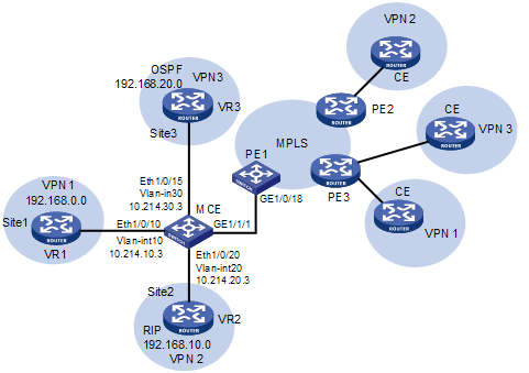
Network Diagram
Figure 1-1 Network diagram for MCE configuration (redistributing VPN routes by OSPF/RIP/IS-IS)
Networking and Configuration Requirements
l Site 1 runs no routing protocol; Site 2 runs RIP; Site 3 runs OSPF.
l It is required that the MCE device isolate routes between VPNs and advertise all the VPN routes to the PE device using OSPF.
l The procedure of configuring the advertising of VPN routes to the PE device using RIP or IS-IS are different from that of configuring the advertising of VPN routes to the PE device using OSPF in only the configurations described in Perform routing configuration between MCE and PE 1.
Applicable Product Matrix
|
Product series |
Software version |
Hardware version |
|
S3610 Series Ethernet Switches |
Release 5301, Release 5303 |
All versions |
|
S5510 Series Ethernet Switches |
Release 5301, Release 5303 |
All versions |
|
S7500E Series Ethernet Switches |
Release 6100 |
LSQ1SRP1CB SRPU(s), or exclusively EA series LPUs |
|
Release 6300 |
All versions |
Configuration Procedure
![]()
l To distinguish devices, assume that the system name of the MCE device is MCE, the name of the egress router of VPN 1, VPN 2 and VPN 3 is VR1, VR2, and VR3 respectively, and the system name of the PE 1 is PE1.
l This example assumes that VR 1, VR 2, VR 3, and PE 1 are all H3C devices. For configuration commands on devices of other vendors, refer to the relevant user manuals.
1) Configure VPN instances on MCE, and associate the VPN instances with interfaces.
# Configure the MCE device to work in MCE mode and reboot the device.
<MCE> system-view
[MCE] switch-mode mce
[MCE] quit
<MCE> reboot
![]()
When configuring MCE for an S7500E series switch, you do not need to configure the switch-mode mce command and reboot the device.
<MCE> system-view
[MCE] ip vpn-instance vpn1
[MCE-vpn-instance-vpn1] route-distinguisher 10:1
[MCE-vpn-instance-vpn1] quit
[MCE] ip vpn-instance vpn2
[MCE-vpn-instance-vpn2] route-distinguisher 20:1
[MCE-vpn-instance-vpn2] quit
[MCE] ip vpn-instance vpn3
[MCE-vpn-instance-vpn3] route-distinguisher 30:1
# Create VLAN 10, add port Ethernet 1/0/10 to VLAN 10, and create VLAN-interface 10.
[MCE-vpn-instance-vpn3] quit
[MCE] vlan 10
[MCE-vlan10] port Ethernet 1/0/10
[MCE-vlan10] quit
[MCE] interface Vlan-interface 10
# Bind VLAN-interface 10 to instance VPN 1, and assign IP address 10.214.10.3/24 to VLAN-interface 10.
[MCE-Vlan-interface10] ip binding vpn-instance vpn1
[MCE-Vlan-interface10] ip address 10.214.10.3 24
[MCE-Vlan-interface10] quit
# Create VLAN 20, add port Ethernet 1/0/20 to VLAN 20, and then create VLAN-interface 20, bind VLAN-interface 20 to instance VPN 2, and assign IP address 10.214.20.3/24 to VLAN-interface 20.
[MCE] vlan 20
[MCE-vlan20] port Ethernet 1/0/20
[MCE-vlan20] quit
[MCE] interface Vlan-interface 20
[MCE-Vlan-interface20] ip binding vpn-instance vpn2
[MCE-Vlan-interface20] ip address 10.214.20.3 24
[MCE-Vlan-interface20] quit
# Create VLAN 30, add port Ethernet 1/0/15 to VLAN 30, and then create VLAN-interface 30, bind VLAN-interface 30 to instance VPN 3, and assign IP address 10.214.30.3/24 to VLAN-interface 30.
[MCE] vlan 30
[MCE-vlan30] port Ethernet 1/0/15
[MCE-vlan30] quit
[MCE] interface Vlan-interface 30
[MCE-Vlan-interface30] ip binding vpn-instance vpn3
[MCE-Vlan-interface30] ip address 10.214.30.3 24
[MCE-Vlan-interface30] quit
2) Perform routing configuration between MCE and Site 1
![]()
As Site 1 is directly connected to MCE and runs no routing protocol, you can configure a static route between them.
l Configuration on VR 1
# Create a VLAN, add the port connecting to MCE to the VLAN, create a VLAN-interface, and then assign IP address 10.214.10.2/24 to the interface. In addition, assign IP address 192.168.0.1/24 to the interface connecting to Site 1. The detailed configuration steps are similar to those for MCE and are therefore omitted.
# Configure a default route, specifying the next hop address as 10.214.10.3.
<VR1> system-view
[VR1] ip route-static 0.0.0.0 0.0.0.0 10.214.10.3
l Configuration on MCE
# Define a static route to network segment 192.168.0.0, specifying the next hop address as 10.214.10.2 and binding the route to instance VPN 1.
[MCE-Vlan-interface20] quit
[MCE] ip route-static vpn-instance vpn1 192.168.0.0 16 10.214.10.2
# Display the routing information of instance VPN 1.
[MCE] display ip routing-table vpn-instance vpn1
Routing Tables: vpn1
Destinations : 5 Routes : 5
Destination/Mask Proto Pre Cost NextHop Interface
127.0.0.0/8 Direct 0 0 127.0.0.1 InLoop0
127.0.0.1/32 Direct 0 0 127.0.0.1 InLoop0
10.214.10.0/24 Direct 0 0 10.214.10.3 Vlan10
10.214.10.3/32 Direct 0 0 127.0.0.1 InLoop0
192.168.0.0/16 Static 60 0 10.214.10.2 Vlan10
As shown in the output information above, a static route has been installed for Site 1.
3) Perform routing configuration between MCE and Site 2
l Configuration on VR 2
# Assign IP address 10.214.20.2/24 to the interface connecting to MCE. (Omitted)
# Configure RIP and advertise network segments 192.168.10.0 and 10.214.20.0.
<VR2> system-view
[VR2] rip 20
[VR2-rip-20] network 192.168.10.0
[VR2-rip-20] network 10.0.0.0
l Configuration on MCE
![]()
As Site 2 runs RIP, you can configure RIP on MCE, so that MCE can update the routing information of the VPN instance for Site 2 automatically.
# Create RIP process 20 and bind it to instance VPN 2.
[MCE] rip 20 vpn-instance vpn2
# Advertise the network segment 10.214.10.0, disable automatic route summarization, and redistribute the routing information of OSPF process 20. Note that, when the routing protocol between the MCE and the PE is RIP or IS-IS, you need to change the ospf keyword in the import-route command to rip or isis.
[MCE-rip-20] network 10.0.0.0
[MCE-rip-20] undo summary
[MCE-rip-20] import-route ospf
# Display the routing information of instance VPN 2.
[MCE-rip-20] display ip routing-table vpn-instance vpn2
Routing Tables: vpn2
Destinations : 5 Routes : 5
Destination/Mask Proto Pre Cost NextHop Interface
127.0.0.0/8 Direct 0 0 127.0.0.1 InLoop0
127.0.0.1/32 Direct 0 0 127.0.0.1 InLoop0
10.214.20.0/24 Direct 0 0 10.214.20.3 Vlan20
10.214.20.3/32 Direct 0 0 127.0.0.1 InLoop0
192.168.10.0/24 RIP 100 1 10.214.20.2 Vlan20
As shown in the output information above, MCE has learnt a private route of Site 2 through RIP, which is maintained in a routing table different from that of Site 1. This achieves the isolation of routes of different VPNs.
4) Perform routing configuration between MCE and Site 3
l Configuration on VR 3
# Assign IP address 10.214.30.2/24 to the interface connecting to MCE. (Omitted)
# Create OSPF process 30 and advertise network segments 192.168.20.0 and 10.214.30.0.
<VR3> system-view
[VR3] ospf 30
[VR3-ospf-30] area 0
[VR3-ospf-30-area-0.0.0.0] network 192.168.20.0 0.0.0.255
[VR3-ospf-30-area-0.0.0.0] network 10.214.30.0 0.0.0.255
l Configuration on MCE
![]()
As Site 3 runs OSPF, you can configure OSPF on MCE, so that MCE can update the routing computation of VPN instance for Site 3 automatically.
# Configure interface Loopback 0 on MCE to specify the router ID for MCE. Assign IP address 101.101.10.1 to the interface. (Omitted)
# Create OSPF process 30, binding it to instance VPN 3, configure OSPF multi-instance (not required when only one OSPF process exists on the MCE), and advertise network segment 10.214.30.0. Note that, when RIP or IS-IS is used as the routing protocol between MCE and PE, you need not configure OSPF multi-instance.
<MCE> system-view
[MCE] ospf 30 router id 101.101.10.1 vpn-instance vpn3
[MCE-ospf-30] vpn-instance-capability simple
[MCE-ospf-30] area 0
[MCE-ospf-30-area-0.0.0.0] network 10.214.30.0 0.0.0.255
# Display the routing information of instance VPN 3.
[MCE-ospf-30-area-0.0.0.0] display ip routing-table vpn-instance vpn3
Routing Tables: vpn3
Destinations : 5 Routes : 5
Destination/Mask Proto Pre Cost NextHop Interface
10.214.30.0/24 Direct 0 0 10.214.30.3 Vlan30
10.214.30.3/32 Direct 0 0 127.0.0.1 InLoop0
127.0.0.0/8 Direct 0 0 127.0.0.1 InLoop0
127.0.0.1/32 Direct 0 0 127.0.0.1 InLoop0
192.168.20.0/24 OSPF 10 2 10.214.30.2 Vlan30
As shown in the above output, MCE has learnt a private route of Site 3 through OSPF.
5) Perform routing configuration between MCE and PE 1
l Configuration on MCE
# Configure port GigabitEthernet 1/1/1 of MCE as a trunk port and specify it to permit tagged packets of VLAN 10, VLAN 20, and VLAN 30.
[MCE] interface GigabitEthernet 1/1/1
[MCE-GigabitEthernet1/1/1] port link-type trunk
[MCE-GigabitEthernet1/1/1] port trunk permit vlan 10 20 30
# Create OSPF process 10, binding the process to instance VPN 1, and set the OSPF domain ID to 10. Advertise the network segment 10.214.10.0 within Area 0, and redistribute static routes of VPN 1.
[MCE-GigabitEthernet1/1/1] quit
[MCE] ospf 10 router-id 101.101.10.1 vpn-instance vpn1
[MCE-ospf-10] domain-id 10
[MCE-ospf-10] area 0
[MCE-ospf-10-area-0.0.0.0] network 10.214.10.0 0.0.0.255
[MCE-ospf-10-area-0.0.0.0] quit
[MCE-ospf-10] import-route static
[MCE-ospf-10] quit
# Create OSPF process 20, binding the process to instance VPN 2, and set the OSPF domain ID to 20. Advertise the network segment 10.214.20.0 within Area 0, and redistribute static routes of VPN 2.
[MCE] ospf 20 router-id 101.101.10.1 vpn-instance vpn2
[MCE-ospf-20] domain-id 20
[MCE-ospf-20] area 0
[MCE-ospf-20-area-0.0.0.0] network 10.214.20.0 0.0.0.255
[MCE-ospf-20-area-0.0.0.0] quit
[MCE-ospf-20] import-route rip
# Create OSPF process 30, binding the process to instance VPN 3, and set the OSPF domain ID to 30. Advertise the network segment 10.214.30.0 within Area 0
[MCE] ospf 30 router-id 101.101.10.1 vpn-instance vpn3
[MCE-ospf-30] domain-id 30
[MCE-ospf-30] area 0
[MCE-ospf-30-area-0.0.0.0] network 10.214.30.0 0.0.0.255
[MCE-ospf-30-area-0.0.0.0] quit
l Configuration on PE 1
# Configure GigabitEthernet 1/0/18 of PE 1 as a trunk port and configure it to allow tagged packets of VLAN 10, VLAN 20 and VLAN 30.
<PE> system-view
[PE] interface GigabitEthernet 1/0/18
[PE-GigabitEthernet1/0/18] port link-type trunk
[PE-GigabitEthernet1/0/18] port trunk permit vlan 10 20 30
# Configure interface VLAN-interface 10, VLAN-interface 20 and VLAN-interface 30, assign IP addresses 10.214.10.4, 10.214.20.4 and 10.214.30.4 to them respectively, and bind them to instances VPN 1, VPN 2, and VPN 3 respectively. (Omitted)
# Configure Loopback 0 on PE 1 to specify the router ID for PE 1. The IP address for Loopback 0 of PE 1 is 100.100.10.1. (Omitted)
# Create OSPF process 10, binding the process to instance VPN 1, set the OSPF domain ID to 10, and advertise the network segment 10.214.10.0 within Area 0.
[PE-Ethernet1/0/18] quit
[PE] ospf 10 router-id 100.100.10.1 vpn-instance vpn1
[PE-ospf-10] domain-id 10
[PE-ospf-10] area 0
[PE-ospf-10-area-0.0.0.0] network 10.214.10.0 0.0.0.255
# Create OSPF process 20 and 30, binding them to instance VPN 2 and VPN 3 respectively, set the OSPF domain ID to 20 and 30, and advertise the network segment 10.214.20.0 and 10.214.30.0 within Area 0 respectively. (Omitted)
# Display the routing information of VPN 1.
[PE-ospf-10-area-0.0.0.0] display ip routing-table vpn-instance vpn1
Routing Tables: vpn1
Destinations : 6 Routes : 6
Destination/Mask Proto Pre Cost NextHop Interface
127.0.0.0/8 Direct 0 0 127.0.0.1 InLoop0
127.0.0.1/32 Direct 0 0 127.0.0.1 InLoop0
10.214.10.0/24 Direct 0 0 10.214.10.4 Vlan10
10.214.10.4/32 Direct 0 0 127.0.0.1 InLoop0
100.100.10.1/32 Direct 0 0 127.0.0.1 InLoop0
192.168.0.0/16 O_ASE 150 1 10.214.10.2 Vlan10
As shown in the output information above, the static route of Site 1 has been redistributed to the routing table of OSPF process 10 on PE 1.
# Display the routing information of VPN 2.
<PE> display ip routing-table vpn-instance vpn2
Routing Tables: vpn2
Destinations : 6 Routes : 6
Destination/Mask Proto Pre Cost NextHop Interface
127.0.0.0/8 Direct 0 0 127.0.0.1 InLoop0
127.0.0.1/32 Direct 0 0 127.0.0.1 InLoop0
10.214.20.0/24 Direct 0 0 10.214.20.4 Vlan20
10.214.20.4/32 Direct 0 0 127.0.0.1 InLoop0
200.200.20.1/32 Direct 0 0 127.0.0.1 InLoop0
192.168.10.0/24 O_ASE 150 1 10.214.20.2 Vlan20
# Display the routing information of VPN 3.
<PE> display ip routing-table vpn-instance vpn3
Routing Tables: vpn3
Destinations : 6 Routes : 6
Destination/Mask Proto Pre Cost NextHop Interface
127.0.0.0/8 Direct 0 0 127.0.0.1 InLoop0
127.0.0.1/32 Direct 0 0 127.0.0.1 InLoop0
10.214.30.0/24 Direct 0 0 10.214.30.4 Vlan30
10.214.30.4/32 Direct 0 0 127.0.0.1 InLoop0
200.200.30.3/32 Direct 0 0 127.0.0.1 InLoop0
192.168.20.0/24 OSPF 10 1 10.214.30.2 Vlan30
After the above configurations, the routing information of VPN 1, VPN 2 and VPN 3 can be advertised to PE 1 properly.
When RIP is used as the routing protocol between the MCE and PE, the configuration procedure is as follows:
l Configuration on MCE
# Connect GigabitEthernet 1/1/1 of MCE to GigabitEthernet 1/0/18 of PE 1, and configure GigabitEthernet 1/1/1 of MCE as a trunk port and specify it to permit tagged packets of VLAN 10, VLAN 20, and VLAN 30.
[MCE] interface GigabitEthernet 1/1/1
[MCE-GigabitEthernet1/1/1] port link-type trunk
[MCE-GigabitEthernet1/1/1] port trunk permit vlan 10 20 30
# Create RIP process 10, binding the process to instance VPN 1, advertise the network segment 10.214.10.0, and redistribute static routes of VPN 1.
[MCE-GigabitEthernet1/1/1] quit
[MCE] rip 10 vpn-instance vpn1
[MCE-rip-10] network 10.0.0.0
[MCE-rip-10] import-route static
[MCE-rip-10] quit
# Create RIP process 20, binding the process to instance VPN 2, and advertise the network segment 10.214.20.0.
[MCE] rip 20 vpn-instance vpn2
[MCE-rip-20] network 10.0.0.0
[MCE-rip-20] quit
# Create RIP process 30, binding the process to instance VPN 3, advertise the network segment 10.214.30.0, and redistribute ospf routes of VPN 2.
[MCE] rip 30 vpn-instance vpn3
[MCE-rip-30] network 10.0.0.0
[MCE-rip-30] import-route ospf
[MCE-rip-30] quit
l Configuration on PE 1
# Configure GigabitEthernet 1/0/18 of PE 1 as a trunk port and configure it to allow tagged packets of VLAN 10, VLAN 20 and VLAN 30.
<PE1> system-view
[PE1] interface GigabitEthernet 1/0/18
[PE1-GigabitEthernet1/0/18] port link-type trunk
[PE1-GigabitEthernet1/0/18] port trunk permit vlan 10 20 30
[PE1-GigabitEthernet1/0/18] quit
# Configure interfaces VLAN-interface 10, VLAN-interface 20 and VLAN-interface 30, assign IP addresses 10.214.10.4, 10.214.20.4 and 10.214.30.4 to them respectively, and bind them to instances VPN 1, VPN 2, and VPN 3 respectively. (Omitted)
# Create RIP process 10, binding the process to instance VPN 1, set the RIP domain ID to 10, and advertise the network segment 10.214.10.0.
[PE1] rip 10 vpn-instance vpn1
[PE1-rip-10] network 10.0.0.0
# Create RIP processes 20 and 30, binding them to instance VPN 2 and VPN 3 respectively, and advertise network segments 10.214.20.0 and 10.214.30.0 respectively. (Omitted)
When IS-IS is used as the routing protocol between the MCE and PE, the configuration procedure is as follows:
l Configuration on MCE
# Connect GigabitEthernet 1/1/1 of MCE to GigabitEthernet 1/0/18 of PE 1, configure GigabitEthernet 1/1/1 of MCE as a trunk port, and specify it to permit tagged packets of VLAN 10, VLAN 20, and VLAN 30.
[MCE] interface GigabitEthernet 1/1/1
[MCE-GigabitEthernet1/1/1] port link-type trunk
[MCE-GigabitEthernet1/1/1] port trunk permit vlan 10 20 30
[MCE-GigabitEthernet1/1/1] quit
# Create IS-IS process 10, binding the process to instance VPN 1; set the network entity name to 10.0000.0000.0001.00 and the route type to level-1-2; enable IS-IS process 10 on Vlan-interface 10, and redistribute static routes of VPN 1.
[MCE] isis 10 vpn-instance vpn1
[MCE-isis-10] network-entity 10.0000.0000.0001.00
[MCE-isis-10] is-level level-1-2
[MCE-isis-10] import-route static level-1-2
[MCE-isis-10] quit
[MCE] interface Vlan-interface 10
[MCE-vpn-instance-vpn10] isis enable 10
[MCE-vpn-instance-vpn10] quit
# Create IS-IS process 20, binding the process to instance VPN 2; set the network entity name to 10.0000.0000.0002.00 and the route type to level-1-2; enable IS-IS process 20 on Vlan-interface 20, and redistribute rip routes of VPN 2.
[MCE] isis 20 vpn-instance vpn2
[MCE-isis-20] network-entity 10.0000.0000.0002.00
[MCE-isis-20] is-level level-1-2
[MCE-isis-20] import-route rip level-1-2
[MCE-isis-20] quit
[MCE] interface Vlan-interface 20
[MCE-vpn-instance-vpn20] isis enable 20
[MCE-vpn-instance-vpn20] quit
# Create IS-IS process 30, binding the process to instance VPN 3; set the network entity name to 10.0000.0000.0003.00 and the route type to level-1-2; enable IS-IS process 30 on Vlan-interface 30, and redistribute ospf routes of VPN 3.
[MCE] isis 30 vpn-instance vpn3
[MCE-isis-30] network-entity 10.0000.0000.0003.00
[MCE-isis-30] is-level level-1-2
[MCE-isis-30] import-route ospf level-1-2
[MCE-isis-30] quit
[MCE] interface Vlan-interface 30
[MCE-vpn-instance-vpn30] isis enable 30
[MCE-vpn-instance-vpn30] quit
l Configuration on PE 1
# Configure GigabitEthernet 1/0/18 of PE 1 as a trunk port and configure it to allow tagged packets of VLAN 10, VLAN 20 and VLAN 30.
<PE1> system-view
[PE1] interface GigabitEthernet 1/0/18
[PE1-GigabitEthernet1/0/18] port link-type trunk
[PE1-GigabitEthernet1/0/18] port trunk permit vlan 10 20 30
[PE1-GigabitEthernet1/0/18] quit
# Configure interfaces VLAN-interface 10, VLAN-interface 20 and VLAN-interface 30, assign IP addresses 10.214.10.4, 10.214.20.4 and 10.214.30.4 to them respectively, and bind them to instances VPN 1, VPN 2, and VPN 3 respectively. (Omitted)
# Create IS-IS process 10, binding the process to instance VPN 1, set the network entity name to 10.0000.0000.0004.00 and the route type to level-1-2; enable IS-IS process 10 on Vlan-interface 10.
[PE1] isis 10 vpn-instance vpn1
[PE1-isis-30] network-entity 10.0000.0000.0004.00
[PE1-isis-30] is-level level-1-2
[PE1-isis-30] quit
[PE1] interface Vlan-interface 10
[PE1-Vlan-interface10] isis enable 10
[PE1-Vlan-interface10] quit
# Create IS-IS processes 20 and 30, binding them to instances VPN 2 and VPN 3 respectively, set the network entity names to 10.0000.0000.0005.00 and 10.0000.0000.0006.00 respectively; enable IS-IS process 20 on Vlan-interface 20 and IS-IS process 30 on Vlan-interface 30 (Omitted)
Complete Configuration
![]()
The following lists only the complete configuration of MCE. For configuration of other devices in the network diagram, refer to the device user manual.
If OSPF is the routing protocol between MCE and PE, the complete configuration is as follows:
#
ip vpn-instance vpn1
route-distinguisher 10:1
#
ip vpn-instance vpn2
route-distinguisher 20:1
#
ip vpn-instance vpn3
route-distinguisher 30:1
#
vlan 1
#
vlan 10
#
vlan 20
#
vlan 30
#
interface LoopBack0
ip address 101.101.10.1 255.255.255.255
#
interface Vlan-interface10
ip binding vpn-instance vpn1
ip address 10.214.10.3 255.255.255.0
#
interface Vlan-interface20
ip binding vpn-instance vpn2
ip address 10.214.20.3 255.255.255.0
#
interface Vlan-interface30
ip binding vpn-instance vpn3
ip address 10.214.30.3 255.255.255.0
#
interface Ethernet1/0/10
port access vlan 10
#
interface Ethernet1/0/15
port access vlan 30
#
interface Ethernet1/0/20
port access vlan 20
#
interface GigabitEthernet1/1/1
port link-type trunk
port trunk permit vlan 1 10 20 30
#
ospf 10 router-id 101.101.10.1 vpn-instance vpn1
vpn-instance-capability simple
import-route static
domain-id 0.0.0.10
area 0.0.0.0
network 10.214.10.0 0.0.0.255
#
ospf 20 router-id 101.101.10.1 vpn-instance vpn2
vpn-instance-capability simple
import-route rip 20
domain-id 0.0.0.20
area 0.0.0.0
network 10.214.20.0 0.0.0.255
#
ospf 30 router-id 101.101.10.1 vpn-instance vpn3
vpn-instance-capability simple
domain-id 0.0.0.30
area 0.0.0.0
network 10.214.30.0 0.0.0.255
#
rip 20 vpn-instance vpn2
network 10.0.0.0
import-route ospf 20
#
ip route-static vpn-instance vpn1 192.168.0.0 255.255.0.0 10.214.10.2
If RIP is the routing protocol between MCE and PE, the complete configuration is as follows:
#
ip vpn-instance vpn1
route-distinguisher 10:1
#
ip vpn-instance vpn2
route-distinguisher 20:1
#
ip vpn-instance vpn3
route-distinguisher 30:1
#
vlan 1
#
vlan 10
#
vlan 20
#
vlan 30
#
interface Vlan-interface10
ip binding vpn-instance vpn1
ip address 10.214.10.3 255.255.255.0
#
interface Vlan-interface20
ip binding vpn-instance vpn2
ip address 10.214.20.3 255.255.255.0
#
interface Vlan-interface30
ip binding vpn-instance vpn3
ip address 10.214.30.3 255.255.255.0
#
interface Ethernet1/0/10
port access vlan 10
#
interface Ethernet1/0/15
port access vlan 30
#
interface Ethernet1/0/20
port access vlan 20
#
interface GigabitEthernet1/1/1
port link-type trunk
port trunk permit vlan 1 10 20 30
#
rip 10 vpn-instance vpn1
import-route static
network 10.0.0.0
#
rip 20 vpn-instance vpn2
network 10.0.0.0
#
rip 30 vpn-instance vpn3
import-route ospf 30
network 10.214.30.0 0.0.0.255
#
ospf 30 router-id 101.101.10.1 vpn-instance vpn3
area 0.0.0.0
network 10.214.30.0 0.0.0.255
import-route rip 30
#
ip route-static vpn-instance vpn1 192.168.0.0 255.255.0.0 10.214.10.2
If IS-IS is the routing protocol between MCE and PE, the complete configuration is as follows:
#
ip vpn-instance vpn1
route-distinguisher 10:1
#
ip vpn-instance vpn2
route-distinguisher 20:1
#
ip vpn-instance vpn3
route-distinguisher 30:1
#
vlan 1
#
vlan 10
#
vlan 20
#
vlan 30
#
interface Vlan-interface10
ip binding vpn-instance vpn1
ip address 10.214.10.3 255.255.255.0
isis enable 10
#
interface Vlan-interface20
ip binding vpn-instance vpn2
ip address 10.214.20.3 255.255.255.0
isis enable 20
#
interface Vlan-interface30
ip binding vpn-instance vpn3
ip address 10.214.30.3 255.255.255.0
isis enable 30
#
interface Ethernet1/0/10
port access vlan 10
#
interface Ethernet1/0/15
port access vlan 30
#
interface Ethernet1/0/20
port access vlan 20
#
interface GigabitEthernet1/1/1
port link-type trunk
port trunk permit vlan 1 10 20 30
#
isis 10 vpn-instance vpn1
is-level level-1-2
network-entity 10.0000.0000.0001.00
import-route static level-1-2
#
isis 20 vpn-instance vpn2
is-level level-1-2
network-entity 10.0000.0000.0002.00
import-route rip 20 level-1-2
#
isis 30 vpn-instance vpn3
is-level level-1-2
network-entity 10.0000.0000.0003.00
import-route ospf 30 level-1-2
#
ospf 30 router-id 101.101.10.1 vpn-instance vpn3
area 0.0.0.0
network 10.214.30.0 0.0.0.255
import-route isis 30
#
rip 20 vpn-instance vpn2
network 10.0.0.0
import-route isis 20
#
ip route-static vpn-instance vpn1 192.168.0.0 255.255.0.0 10.214.10.2
Configuration Guidelines
None
Configuring MCE (Redistributing VPN Routes by BGP)
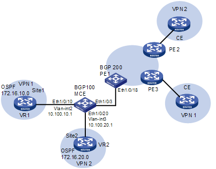
Network Diagram
Figure 1-2 Network diagram for MCE configuration (redistributing VPN routes by BGP
Networking and Configuration Requirements
l OSPF runs within both site 1 and site 2, and EBGP runs between MCE and PE.
Applicable Product Matrix
|
Product series |
Software version |
Hardware version |
|
S3610 Series Ethernet Switches |
Release 5301, Release 5303 |
All versions |
|
S5510 Series Ethernet Switches |
Release 5301, Release 5303 |
All versions |
|
S7500E Series Ethernet Switches |
Release 6100 |
LSQ1SRP1CB SRPU(s), or exclusively EA series LPUs |
|
Release 6300 |
All versions |
Configuration Procedure
![]()
l To distinguish devices, assume that the system name of the MCE device is MCE, the name of the egress router of VPN 1, VPN 2 and VPN 3 is VR1, VR2, and VR3 respectively, and the system name of the PE 1 is PE1.
l This example assumes that VR 1, VR 2, VR 3, and PE 1 are all H3C devices. For configuration commands on devices of other vendors, refer to the relevant user manuals.
1) Configure VPN instances on MCE, and associate the VPN instances with interfaces.
# Configure the MCE device to work in the MCE mode and reboot the device.
<MCE> system-view
[MCE] switch-mode mce
[MCE] quit
<MCE> reboot
![]()
When configuring MCE for an S7500E series switch, you do not need to configure the switch-mode mce command and reboot the device.
# Configure VPN instances VPN 1 and VPN 2 on MCE; set the route distinguishers (RDs) to 10:1 and 20:1 respectively; set the same values for the VPN (both export and import) target attributes.
<MCE> system-view
[MCE] ip vpn-instance vpn1
[MCE-vpn-instance-vpn1] route-distinguisher 10:1
[MCE-vpn-instance-vpn1] vpn-target 10:1 both
[MCE-vpn-instance-vpn1] quit
[MCE] ip vpn-instance vpn2
[MCE-vpn-instance-vpn2] route-distinguisher 20:1
[MCE-vpn-instance-vpn2] vpn-target 20:1 both
[MCE-vpn-instance-vpn2] quit
# Create VLAN 2, assign port Ethernet 1/0/10 to VLAN 2, and create VLAN-interface 2.
[MCE] vlan 2
[MCE-vlan2] port Ethernet 1/0/10
[MCE-vlan2] quit
[MCE] interface Vlan-interface 2
# Bind VLAN-interface 2 to instance VPN 1; configure the IP address of the VLAN interface as 10.100.10.1 and the mask as 24 bits.
[MCE-Vlan-interface2] ip binding vpn-instance vpn1
[MCE-Vlan-interface2] ip address 10.100.10.1 24
[MCE-Vlan-interface2] quit
# Take similar steps to configure VLAN 3; assign Ethernet 1/0/20 to VLAN 3; bind the VLAN interface to instance VPN 2, and assign an IP address to the VLAN interface.
[MCE] vlan 3
[MCE-vlan3] port Ethernet 1/0/20
[MCE-vlan3] quit
[MCE] interface Vlan-interface 3
[MCE-Vlan-interface3] ip binding vpn-instance vpn2
[MCE-Vlan-interface3] ip address 10.100.20.1 24
[MCE-Vlan-interface3] quit
2) Perform routing configuration between MCE and Site 1
l Configuration on VR 1
# Create OSPF process 10 on VR 1 and advertise network segments 172.16.10.0 and 10.100.10.0 within area 0.
<VR1> system-view
[VR1] ospf 10
[VR1-ospf-10] area 0
[VR1-ospf-10-area-0.0.0.0] network 10.100.10.0 0.0.0.255
[VR1-ospf-10-area-0.0.0.0] network 172.16.10.0 0.0.0.255
l Configuration on MCE
# Create OSPF process 10 for MCE and bind OSPF process 10 to VPN 1; set the router ID to 10.10.10.1; redistribute the BGP routing information of VPN 1, configure OSPF multi-instance, and advertise network segment 10.100.10.0.
<MCE> system-view
[MCE] ospf 10 router-id 10.10.10.1 vpn-instance vpn1
[MCE-ospf-10] vpn-instance capability simple
[MCE-ospf-10] import-route bgp
[MCE-ospf-10] area 0
[MCE-ospf-10-area-0.0.0.0] network 10.100.10.0 0.0.0.255
# Display the routing information of instance VPN 1.
[MCE-ospf-10-area-0.0.0.0] display ip routing-table vpn-instance vpn1
Routing Tables: vpn1
Destinations : 5 Routes : 5
Destination/Mask Proto Pre Cost NextHop Interface
127.0.0.0/8 Direct 0 0 127.0.0.1 InLoop0
127.0.0.1/32 Direct 0 0 127.0.0.1 InLoop0
10.100.10.0/24 Direct 0 0 10.100.10.1 Vlan2
10.100.10.1/32 Direct 0 0 127.0.0.1 InLoop0
172.16.10.0/24 OSPF 10 1 10.100.10.2 Vlan2
As shown in the output information above, MCE has learnt the routing information of Site 1 through OSPF process 10.
3) Perform routing configuration between MCE and Site 2
l Configuration on VR 2
# Create OSPF process 20 and advertise network segments 172.16.20.0 and 10.100.20.0 within area 0.
<VR2> system-view
[VR2] ospf 20
[VR2-ospf-20] area 0
[VR2-ospf-20-area-0.0.0.0] network 10.100.20.0 0.0.0.255
[VR2-ospf-20-area-0.0.0.0] network 172.16.20.0 0.0.0.255
l Configuration on MCE
# Create OSPF process 20 for MCE and bind OSPF process 20 to instance VPN 2; set the router ID to 10.10.10.1; redistribute the BGP routing information of VPN 2, configure OSPF multi-instance, and advertise network segment 10.100.20.0.
<MCE> system-view
[MCE] ospf 20 router-id 10.10.10.1 vpn-instance vpn2
[MCE-ospf-20] vpn-instance capability simple
[MCE-ospf-20] import-route bgp
[MCE-ospf-20] area 0
[MCE-ospf-20-area-0.0.0.0] network 10.100.20.0 0.0.0.255
# Display the routing information of instance VPN 2.
[MCE] display ip routing-table vpn-instance vpn2
Routing Tables: vpn2
Destinations : 5 Routes : 5
Destination/Mask Proto Pre Cost NextHop Interface
127.0.0.0/8 Direct 0 0 127.0.0.1 InLoop0
127.0.0.1/32 Direct 0 0 127.0.0.1 InLoop0
10.100.20.0/24 Direct 0 0 10.100.20.1 Vlan3
10.100.20.1/32 Direct 0 0 127.0.0.1 InLoop0
172.16.20.0/24 OSPF 10 1 10.100.20.2 Vlan3
4) Perform routing configuration between MCE and PE 1
l Configuration on MCE
# Configure port Ethernet 1/0/3 of MCE as a trunk port and specify to permit tagged packets of VLAN 2, and VLAN 3.
[MCE] interface Ethernet 1/0/3
[MCE-Ethernet1/0/3] port link-type trunk
[MCE-Ethernet1/0/3] port trunk permit vlan 2 3
# Create BGP process 100 for MCE.
[MCE] bgp 100
[MCE-bgp]
# Enter the IPv4 address family view of instance VPN 1.
[MCE-bgp] ipv4-family vpn-instance vpn1
[MCE-bgp-vpn1]
# Configure PE 1 as an EBGP peer and inject the routing information of OSPF process 10 (assuming that the address of the interface bound to VPN 1 is 10.100.10.3 and the ID of the BGP process is 200).
[MCE-bgp-vpn1] peer 10.100.10.3 as-number 200
[MCE-bgp-vpn1] import-route ospf 10
[MCE-bgp-vpn1] quit
# Enter the IPv4 address family view of instance VPN 2, specify PE 1 as an EBGP peer and inject the routing information of OSPF process 20 (assuming that the address of the interface bound to VPN 2 is 10.100.20.3 and the ID of the BGP process is 200).
[MCE-bgp] ipv4-family vpn-instance vpn2
[MCE-bgp-vpn2] peer 10.100.20.3 as-number 200
[MCE-bgp-vpn2] import-route ospf 20
l Configuration on PE 1
# Configure Ethernet 1/0/18 of PE 1 as a trunk port and configure it to allow tagged packets of VLAN 2, and VLAN3 to pass through.
<PE1> system-view
[PE1] interface Ethernet1/0/18
[PE1-Ethernet1/0/18] port link-type trunk
[PE1-Ethernet1/0/18] port trunk permit vlan 2 3
# Configure interface VLAN-interface 2 and VLAN-interface 3, assign IP addresses 10.100.10.3 and 10.100.20.3 to them respectively, and bind them to instance VPN 1 and VPN 2 respectively. (Omitted)
# Create BGP process 200 on PE 1, and configure MCE as an EBGP peer in the IPv4 address family view of the two VPN instances respectively.
[PE1] bgp 200
[PE1-bgp] ipv4-family vpn-instance vpn1
[PE1-bgp-vpn1] peer 10.100.10.1 as-number 100
[PE1-bgp-vpn1] quit
[PE1-bgp] ipv4-family vpn-instance vpn2
[PE1-bgp-vpn2] peer 10.100.20.1 as-number 100
[PE1-bgp-vpn2] return
# Display the routing information of VPN 1 on PE 1.
<PE1> display ip routing-table vpn-instance vpn1
Routing Tables: vpn1
Destinations : 5 Routes : 5
Destination/Mask Proto Pre Cost NextHop Interface
127.0.0.0/8 Direct 0 0 127.0.0.1 InLoop0
127.0.0.1/32 Direct 0 0 127.0.0.1 InLoop0
10.100.10.0/24 Direct 0 0 10.100.10.3 Vlan2
10.100.10.3/32 Direct 0 0 127.0.0.1 InLoop0
172.16.10.0/24 BGP 255 2 10.100.10.2 Vlan2
# Display the routing information of VPN 2 on PE 1.
<PE1> display ip routing-table vpn-instance vpn2
Routing Tables: vpn2
Destinations : 5 Routes : 5
Destination/Mask Proto Pre Cost NextHop Interface
127.0.0.0/8 Direct 0 0 127.0.0.1 InLoop0
127.0.0.1/32 Direct 0 0 127.0.0.1 InLoop0
10.100.20.0/24 Direct 0 0 10.100.20.3 Vlan3
10.100.20.3/32 Direct 0 0 127.0.0.1 InLoop0
172.16.20.0/24 BGP 255 2 10.100.20.2 Vlan3
After the above configurations, MCE has imported the OSPF routing information of VPN 1 and VPN 2 to the EBGP routing table of PE 1 properly.
Complete Configuration
#
ip vpn-instance vpn1
route-distinguisher 10:1
vpn-target 10:1 export-extcommunity
vpn-target 10:1 import-extcommunity
#
ip vpn-instance vpn2
route-distinguisher 20:1
vpn-target 20:1 export-extcommunity
vpn-target 20:1 import-extcommunity
#
vlan 1
#
vlan 10
#
vlan 20
#
interface LoopBack0
ip address 101.10.10.1 255.255.255.255
#
interface Vlan-interface10
ip binding vpn-instance vpn1
ip address 10.100.10.1 255.255.255.0
#
interface Vlan-interface20
ip binding vpn-instance vpn2
ip address 10.100.20.1 255.255.255.0
#
interface Ethernet1/0/10
port access vlan 10
#
interface Ethernet1/0/20
port access vlan 20
#
interface GigabitEthernet1/1/1
port link-type trunk
port trunk permit vlan 1 10 20
#
bgp 100
undo synchronization
ipv4-family vpn-instance vpn1
peer 10.100.10.3 as-number 200
import-route ospf 10
#
ipv4-family vpn-instance vpn2
peer 10.100.10.3 as-number 200
import-route ospf 20
#
ospf 10 router-id 10.10.10.1 vpn-instance vpn1
vpn-instance-capability simple
area 0.0.0.0
network 10.100.10.0 0.0.0.255
import-route bgp
#
ospf 10 router-id 10.10.20.1 vpn-instance vpn2
vpn-instance-capability simple
area 0.0.0.0
network 10.100.20.0 0.0.0.255
import-route bgp
Configuration Guidelines
The VPN target values of the VPNs configured on MCE must match those configured on the PE.