- Table of Contents
-
- H3C Low-End and Mid-Range Ethernet Switches Configuration Examples(V1.01)
- 00-1Cover
- 01-Login Configuration Guide
- 02-VLAN Configuration Guide
- 03-GVRP Configuration Guide
- 04-Voice VLAN Configuration Guide
- 05-IP Addressing and Performance Configuration Guide
- 06-QinQ Configuration Guide
- 07-BPDU Tunnel Configuration Guide
- 08-VLAN Mapping Configuration Guide
- 09-MAC Address Table Management Configuration Guide
- 10-Link Aggregation Configuration Guide
- 11-IP Source Guard Configuration Guide
- 12-DLDP Configuration Guide
- 13-MSTP Configuration Guide
- 14-IPv4 Routing Configuration Guide
- 15-IPv6 Configuration Guide
- 16-IPv6 Routing Configuration Guide
- 17-IPv4 Multicast Configuration Guide
- 18-IPv6 Multicast Configuration Examples
- 19-802.1x Configuration Guide
- 20-AAA Configuration Guide
- 21-MAC Authentication Configuration Guide
- 22-Portal Configuration Guide
- 23-ARP Configuration Guide
- 24-DHCP Configuration Guide
- 25-ACL Configuration Guide
- 26-QoS Configuration Guide
- 27-Port Mirroring Configuration Guide
- 28-Cluster Management Configuration Guide
- 29-SNMP-RMON Configuration Guide
- 30-NTP Configuration Guide
- 31-FTP-TFTP Configuration Guide
- 32-UDP Helper Configuration Guide
- 33-Information Center Configuration Guide
- 34-DNS Configuration Guide
- 35-File System Management Configuration Guide
- 36-Remote Upgrade Configuration Guide
- 37-NQA Configuration Guide
- 38-VRRP Configuration Guide
- 39-SSH Configuration Guide
- 40-Port Security Configuration Guide
- 41-Port Isolation Configuration Guide
- 42-LLDP Configuration Guide
- 43-MCE Configuration Guide
- 44-PoE Configuration Guide
- 45-OAM Configuration Guide
- 46-Connectivity Fault Detection Configuration Guide
- 47-RRPP Configuration Guide
- 48-sFlow Configuration Guide
- 49-SSL-HTTPS Configuration Guide
- 50-PKI Configuration Guide
- 51-Track Configuration Guide
- 52-EPON-OLT Configuration Guide
- 53-Smart Link Configuration Guide
- 54-MPLS Configuration Guide
- Related Documents
-
| Title | Size | Download |
|---|---|---|
| 20-AAA Configuration Guide | 122.07 KB |
Configuring AAA by HWTACACS Server for Telnet Users
Networking and Configuration Requirements
Configuring AAA by Separate Servers for Telnet Users
Networking and Configuration Requirements
Configuring AAA by RADIUS Server for SSH Users
Networking and Configuration Requirements
Networking and Configuration Requirements
1 AAA Configuration Guide
AAA Overview
Authentication, Authorization, and Accounting (AAA) provides a uniform framework for configuring these three security functions to implement network security management.
AAA usually uses a client/server model, where the client runs on the network access server (NAS) and the server maintains user information centrally. In an AAA network, a NAS is a server for users but a client for the AAA servers, as shown in Figure 1-1.
Figure 1-1 AAA networking diagram
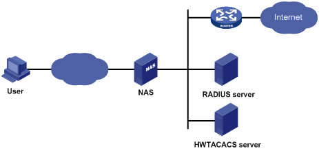
When a user tries to establish a connection with the NAS and to obtain the rights to access other networks or some network resources, the NAS authenticates the user or the corresponding connection. The NAS can transparently pass the user’s AAA information to the server (RADIUS server or HWTACACS server). The RADIUS/HWTACACS protocol defines how to exchange user information between a NAS and a server.
Configuring AAA by HWTACACS Server for Telnet Users
Network Diagram
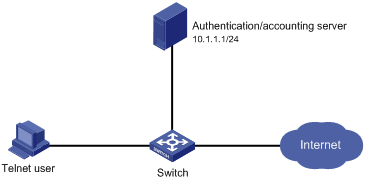
Figure 1-2 Configure AAA by an HWTACACS server for Telnet users
Networking and Configuration Requirements
As shown in Figure 1-2, configure the switch to use the HWTACACS server to provide authentication, authorization, and accounting services for login users and use local authentication instead when the HWTACACS server is not available.
l The HWTACACS server is used for authentication, authentication, and accounting. Its IP address is 10.1.1.1.
l On the switch, set the shared keys for authentication, authorization, and accounting packets to expert, and specify that the switch send usernames without domain names to the HWTACACS server.
l On the HWTACACS server, set the shared keys for packet exchange with the switch to expert.
Applicable Product Matrix
|
Product series |
Software version |
Hardware version |
|
S3610 Series Ethernet Switches |
Release 5301, Release 5303 |
All versions |
|
S5510 Series Ethernet Switches |
Release 5301, Release 5303 |
All versions |
|
S5500-SI Series Ethernet Switches |
Release 1207 |
All versions except S5500-20TP-SI |
|
Release 1301 |
S5500-20TP-SI |
|
|
S5500-EI Series Ethernet Switches |
Release 2102 |
All versions |
|
S7500E Series Ethernet Switches |
Release 6100, Release 6300 |
All versions |
Configuration Procedure
# Enable the Telnet server on the switch.
<Switch> system-view
[Switch] telnet server enable
# Configure the switch to use AAA for Telnet users.
[Switch] user-interface vty 0 4
[Switch-ui-vty0-4] authentication-mode scheme
[Switch-ui-vty0-4] quit
# Configure the HWTACACS scheme.
[Switch] hwtacacs scheme hwtac
[Switch-hwtacacs-hwtac] primary authentication 10.1.1.1 49
[Switch-hwtacacs-hwtac] primary authorization 10.1.1.1 49
[Switch-hwtacacs-hwtac] primary accounting 10.1.1.1 49
[Switch-hwtacacs-hwtac] key authentication expert
[Switch-hwtacacs-hwtac] key authorization expert
[Switch-hwtacacs-hwtac] key accounting expert
[Switch-hwtacacs-hwtac] user-name-format without-domain
[Switch-hwtacacs-hwtac] quit
# Apply the AAA scheme to the domain.
[Switch] domain 1
[Switch-isp-1] authentication login hwtacacs-scheme hwtac local
[Switch-isp-1] authorization login hwtacacs-scheme hwtac local
[Switch-isp-1] accounting login hwtacacs-scheme hwtac local
[Switch-isp-1] quit
# Create a local user named telnet.
[Switch] local-user telnet
[Switch-luser-telnet] service-type telnet
[Switch-luser-telnet] password simple telnet
Complete Configuration
#
telnet server enable
#
hwtacacs scheme hwtac
primary authentication 10.1.1.1
primary authorization 10.1.1.1
primary accounting 10.1.1.1
key authentication expert
key authorization expert
key accounting expert
user-name-format without-domain
#
domain 1
authentication login hwtacacs-scheme hwtac local
authorization login hwtacacs-scheme hwtac local
accounting login hwtacacs-scheme hwtac local
#
user-interface aux 0
user-interface vty 0 4
authentication-mode scheme
#
local-user telnet
service-type telnet
password simple telnet
Configuration Guidelines
When telneting into the switch, a user enters username userid@1 for authentication using domain 1.
Configuring AAA by Separate Servers for Telnet Users
Network Diagram
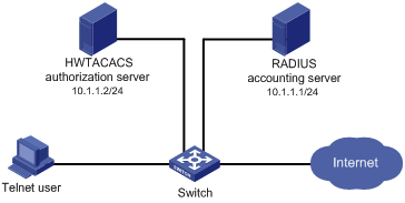
Figure 1-3 Configure AAA by separate servers for Telnet users
Networking and Configuration Requirements
As shown in Figure 1-3, configure the switch to provide local authentication, HWTACACS authorization, and RADIUS accounting services for the Telnet user. The username and the password for the Telnet user are both telnet.
l The HWTACACS server is used for authorization. Its IP address is 10.1.1.2. On the switch, set the shared key for packet exchange with the HWTACACS server to expert, and specify that the switch send usernames without domain names to the HWTACACS server.
l The RADIUS server is used for accounting. Its IP address is 10.1.1.1. On the switch, set the shared key for packet exchange with the RADIUS server to expert.
![]()
Configuration of separate AAA for other types of users is similar to that given in this example. The only difference lies in the access type.
Applicable Product Matrix
|
Product series |
Software version |
Hardware version |
|
S3610 Series Ethernet Switches |
Release 5301, Release 5303 |
All versions |
|
S5510 Series Ethernet Switches |
Release 5301, Release 5303 |
All versions |
|
S5500-SI Series Ethernet Switches |
Release 1207 |
All versions except S5500-20TP-SI |
|
Release 1301 |
S5500-20TP-SI |
|
|
S5500-EI Series Ethernet Switches |
Release 2102 |
All versions |
|
S7500E Series Ethernet Switches |
Release 6100, Release 6300 |
All versions |
Configuration Procedure
# Assign IP addresses to the interfaces (omitted).
# Enable the Telnet server on the switch.
<Switch> system-view
[Switch] telnet server enable
# Configure the switch to use AAA for Telnet users.
[Switch] user-interface vty 0 4
[Switch-ui-vty0-4] authentication-mode scheme
[Switch-ui-vty0-4] quit
# Configure the HWTACACS scheme.
[Switch] hwtacacs scheme hwtac
[Switch-hwtacacs-hwtac] primary authorization 10.1.1.2 49
[Switch-hwtacacs-hwtac] key authorization expert
[Switch-hwtacacs-hwtac] user-name-format without-domain
[Switch-hwtacacs-hwtac] quit
# Configure the RADIUS scheme.
[Switch] radius scheme rd
[Switch-radius-rd] primary accounting 10.1.1.1 1813
[Switch-radius-rd] key accounting expert
[Switch-radius-rd] server-type extended
[Switch-radius-rd] user-name-format without-domain
[Switch-radius-rd] quit
# Create a local user named telnet.
[Switch] local-user telnet
[Switch-luser-telnet] service-type telnet
[Switch-luser-telnet] password simple telnet
# Configure the AAA schemes of the ISP domain.
[Switch] domain 1
[Switch-isp-1] authentication login local
[Switch-isp-1] authorization login hwtacacs-scheme hwtac
[Switch-isp-1] accounting login radius-scheme rd
[Switch-isp-1] quit
Complete Configuration
#
telnet server enable
#
hwtacacs scheme hwtac
primary authorization 10.1.1.2
key authorization expert
user-name-format without-domain
#
radius scheme rd
primary accounting 10.1.1.1 1813
key accounting expert
server-type extended
user-name-format without-domain
#
domain 1
authentication login local
authorization login hwtacacs-scheme hwtac
accounting login radius-scheme rd
#
local-user telnet
password simple telnet
service-type telnet
#
user-interface aux 0
user-interface vty 0 4
authentication-mode scheme
#
Configuration Guidelines
When telneting into the switch, a user enters username telnet@1 for authentication using domain 1.
Configuring AAA by RADIUS Server for SSH Users
Network Diagram
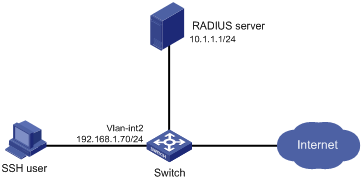
Figure 1-4 Configure AAA by a RADIUS server for SSH users
Networking and Configuration Requirements
As shown in Figure 1-4, configure the switch to use the RADIUS server to provide authentication, authorization, and accounting services for SSH users.
l The RADIUS server is responsible for both authentication and accounting. Its IP address is 10.1.1.1.
l On the switch, set both the shared keys for authentication and accounting exchange with the RADIUS server to expert, and specify that the switch send usernames with domain names to the RADIUS server.
l The RADIUS server runs the CAMS server.
Applicable Product Matrix
|
Product series |
Software version |
Hardware version |
|
S5500-SI Series Ethernet Switches |
Release 1207 |
All versions except S5500-20TP-SI |
|
Release 1301 |
S5500-20TP-SI |
|
|
S5500-EI Series Ethernet Switches |
Release 2102 |
All versions |
|
S7500E Series Ethernet Switches |
Release 6300 |
All versions |
Configuration Procedure
1) Configure the RADIUS server.
![]()
This example assumes that the RADIUS server runs the CAMS server Version 2.10.
# Add an access device.
Log into the CAMS management platform and select System Management > System Configuration from the navigation tree. In the System Configuration window, click Modify of the Access Device item, and then click Add to enter the Add Access Device window and perform the following configurations:
l Specify the IP address of the switch as 192.168.1.70
l Set both the shared keys for authentication and accounting packets to expert
l Select LAN Access Service as the service type
l Specify the ports for authentication and accounting as 1812 and 1813 respectively
l Select Extensible Protocol as the protocol type
l Select Standard as the RADIUS packet type.
# Add an administrator for device management
From the navigation tree, select User Management > User for Device Management, and then in the right pane, click Add to enter the Add Account window and perform the following configurations:
l Add a user named hello@bbb, and specify the password
l Select SSH as the service type
l Specify the IP address range of the hosts to be managed.
2) Configure the switch
# Configure the IP address of VLAN-interface 2, through which the SSH user accesses the switch.
<Switch> system-view
[Switch] interface vlan-interface 2
[Switch-Vlan-interface2] ip address 192.168.1.70 255.255.255.0
[Switch-Vlan-interface2] quit
# Generate RSA and DSA key pairs and enable the SSH server.
[Switch] public-key local create rsa
[Switch] public-key local create dsa
[Switch] ssh server enable
# Configure the switch to use AAA for SSH users.
[Switch] user-interface vty 0 4
[Switch-ui-vty0-4] authentication-mode scheme
# Configure the user interfaces to support SSH.
[Switch-ui-vty0-4] protocol inbound ssh
[Switch-ui-vty0-4] quit
# Configure the RADIUS scheme.
[Switch] radius scheme rad
[Switch-radius-rad] primary authentication 10.1.1.1 1812
[Switch-radius-rad] primary accounting 10.1.1.1 1813
[Switch-radius-rad] key authentication expert
[Switch-radius-rad] key accounting expert
[Switch-radius-rad] user-name-format with-domain
[Switch-radius-rad] quit
# Apply the AAA scheme to the domain.
[Switch] domain bbb
[Switch-isp-bbb] authentication login radius-scheme rad
[Switch-isp-bbb] authorization login radius-scheme rad
[Switch-isp-bbb] accounting login radius-scheme rad
[Switch-isp-bbb] quit
When using SSH to log in, a user enters a username in the form userid@bbb for authentication using domain bbb.
3) Verify the configuration
After the above configuration, the SSH user should be able to use the configured account and to access the user interface of the switch. The commands that the user can access depend on the settings for EXEC users on the CAMS server.
Complete Configuration
#
radius scheme rad
primary authentication 10.1.1.1 1812
primary accounting 10.1.1.1 1813
key authentication expert
key accounting expert
user-name-format with-domain
#
domain bbb
authentication login radius-scheme rad
authorization login radius-scheme rad
accounting login radius-scheme rad
#
ssh server enable
#
user-interface vty 0 4
authentication-mode scheme
protocol inbound ssh
Configuring EAD Application
Network Diagram
Figure 1-5 Configure EAD application
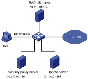
Networking and Configuration Requirements
l Host is connected to interface Ethernet 2/0/1 on the switch.
l Configure the switch to redirect the user to the update server to download the 802.1x client when the user accesses the Internet through IE before passing authentication.
l Configure the switch, RADIUS server, and security policy server, so that the RADIUS server performs remote authentication of users and the security policy server controls EAD operations of users.
![]()
This configuration example gives only the configurations on the switch. For configurations on the RADIUS server and security policy server, refer to the relevant descriptions.
Applicable Product Matrix
|
Product series |
Software version |
Hardware version |
|
S3610 Series Ethernet Switches |
Release 5301, Release 5303 |
All versions |
|
S5510 Series Ethernet Switches |
Release 5301, Release 5303 |
All versions |
|
S5500-SI Series Ethernet Switches |
Release 1207 |
All versions except S5500-20TP-SI |
|
Release 1301 |
S5500-20TP-SI |
|
|
S5500-EI Series Ethernet Switches |
Release 2102 |
All versions |
|
S7500E Series Ethernet Switches |
Release 6100, Release 6300 |
All versions |
Configuration Procedure
1) Configure the Web server
Before using the EAD fast deployment feature, configure the update server as the Web server, that is, the server for downloading the 802.1x client.
2) Configure EAD fast deployment
# Configure a free IP range.
<Switch> system-view
[Switch] dot1x free-ip 10.110.91.0 24
# Configure the URL for HTTP redirection.
[Switch] dot1x url http:// 10.110.91.168
# Enable 802.1x globally.
[Switch] dot1x
# Enable 802.1x for interface Ethernet 2/0/1.
[Switch] interface ethernet 2/0/1
[Switch-Ethernet2/0/1] dot1x
3) Configure EAD
# Configure a RADIUS scheme.
[Switch] radius scheme cams
[Switch-radius-cams] primary authentication 10.110.91.164 1812
[Switch-radius-cams] primary accounting 10.110.91.164 1813
[Switch-radius-cams] key authentication expert
[Switch-radius-cams] key accounting expert
[Switch-radius-cams] user-name-format with-domain
[Switch-radius-cams] server-type extended
# Configure the IP address of the security policy server.
[Switch-radius-cams] security-policy-server 10.110.91.166
# Configure the default AAA schemes.
[Switch] domain aaa
[Switch-isp-aaa] authentication default radius-scheme cams
[Switch-isp-aaa] authorization default radius-scheme cams
[Switch-isp-aaa] accounting default radius-scheme cams
When telneting into the switch, a user enters username userid@aaa for authentication using domain aaa.
4) User login
When a user tries to access the Internet before passing 802.1x authentication, the switch will redirect the user to the update server page, where the user can download the 802.1x client.
After the user downloads and launches the 802.1x client, enters the correct username and password, and passes 802.1x authentication, the security client (software installed on the host) interacts with the security policy server to check the security status of the client. If the client does not satisfy the security requirements, the security policy server issues an ACL to the switch, which then restricts the client to the update server.
After the client installs the required patches and satisfies the security requirements, the security policy server reissues an ACL to the switch, which then allows the client to access more network resources.
Complete Configuration
#
radius scheme cams
primary authentication 10.110.91.164 1812
primary accounting 10.110.91.164 1813
key authentication expert
key accounting expert
user-name-format with-domain
server-type extended
security-policy-server 10.110.91.166
#
domain aaa
authentication default radius-scheme cams
authorization default radius-scheme cams
accounting default radius-scheme cams
#
dot1x
dot1x free-ip 10.110.91.0 24
dot1x url http:// 10.110.91.168
#
interface ethernet 2/0/1
dot1x
#