- Table of Contents
-
- H3C MSR1000[2600][3600] Routers Configuration Examples All-in-One-R9141-6W100
- 00-Preface
- 01-Local 802.1X Authentication Configuration Examples
- 02-RADIUS-Based 802.1X Authentication Configuration Examples
- 03-AAA Configuration Examples
- 04-ACL Configuration Examples
- 05-MPLS over ADVPN Configuration Examples
- 06-ARP Attack Protection Configuration Examples
- 07-BFD Configuration Examples
- 08-Basic BGP Configuration Examples
- 09-BGP Route Attribute-Based Route Selection Configuration Examples
- 10-EAA Monitor Policy Configuration Examples
- 11-GRE with OSPF Configuration Examples
- 12-HoVPN Configuration Examples
- 13-IGMP Snooping Configuration Examples
- 14-IGMP Configuration Examples
- 15-IPsec Configuration Examples
- 16-IPsec Digital Certificate Authentication Configuration Examples
- 17-IPv6 IS-IS Configuration Examples
- 18-IPv6 over IPv4 GRE Tunnel Configuration Examples
- 19-IPv6 over IPv4 Manual Tunnel with OSPFv3 Configuration Examples
- 20-IS-IS Configuration Examples
- 21-Combined ISATAP Tunnel and 6to4 Tunnel Configuration Examples
- 22-L2TP over IPsec Configuration Examples
- 23-Multi-Instance L2TP Configuration Examples
- 24-L2TP Multidomain Access Configuration Examples
- 25-MPLS L3VPN Configuration Examples
- 26-MPLS OAM Configuration Examples
- 27-MPLS TE Configuration Examples
- 28-Basic MPLS Configuration Examples
- 29-NAT DNS Mapping Configuration Examples
- 30-NetStream Configuration Examples
- 31-NQA Configuration Examples
- 32-NTP Configuration Examples
- 33-OSPFv3 Configuration Examples
- 34-OSPF Configuration Examples
- 35-OSPF Multi-Process Configuration Examples
- 36-OSPF Multi-Instance Configuration Examples
- 37-Portal Configuration Examples
- 38-PPP Configuration Examples
- 39-RBAC Configuration Examples
- 40-RMON Configuration Examples
- 41-IPv4 NetStream Sampling Configuration Examples
- 42-SNMP Configuration Examples
- 43-SRv6 Configuration Examples
- 44-SSH Configuration Examples
- 45-Tcl Commands Configuration Examples
- 46-VLAN Configuration Examples
- 47-VRRP Configuration Examples
- 48-VXLAN over IPsec Configuration Examples
- 49-WLAN AC Configuration Examples
- 50-Small and Medium-Sized Store Configuration Examples
- 51-Cloudnet VPN Configuration Examples
- 52-Ethernet Link Aggregation Configuration Examples
- 53-Ethernet OAM Configuration Examples
- 54-Outbound Bidirectional NAT Configuration Examples
- 55-NAT Hairpin in C-S Mode Configuration Examples
- 56-Load Sharing NAT Server Configuration Examples
- 57-BIDIR-PIM Configuration Examples
- 58-Control Plane-Based QoS Policy Configuration Examples
- 59-Scheduling a Task Configuration Examples
- 60-Client-Initiated L2TP Tunnel Configuration Examples
- 61-LAC-Auto-Initiated L2TP Tunnel Configuration Examples
- 62-Authorized ARP Configuration Examples
- 63-GTS Configuration Examples
- 64-Traffic Policing Configuration Examples
- 65-Traffic Accounting Configuration Examples
- 66-Mobile Communication Modem Management Configuration Examples
- 67-Port Isolation Configuration Examples
- 68-PBR Configuration Examples
- 69-TFTP Client Software Upgrade Configuration Examples
- 70-FTP Client Software Upgrade Configuration Examples
- 71-FTP Server Software Upgrade Configuration Examples
- 72-Routing Policy Configuration Examples
- 73-Software Upgrade from the BootWare Menu Configuration Examples
- 74-Mirroring Configuration Examples
- Related Documents
-
| Title | Size | Download |
|---|---|---|
| 72-Routing Policy Configuration Examples | 132.79 KB |
Routing Policy Configuration Examples
Copyright © 2024 New H3C Technologies Co., Ltd. All rights reserved.
No part of this manual may be reproduced or transmitted in any form or by any means without prior written consent of New H3C Technologies Co., Ltd.
Except for the trademarks of New H3C Technologies Co., Ltd., any trademarks that may be mentioned in this document are the property of their respective owners.
The information in this document is subject to change without notice.
Introduction
This document provides routing policy configuration examples.
Routing policies control routing paths by filtering and modifying routing information. Routing policies can filter advertised, received, and redistributed routes, and modify attributes for specific routes.
Prerequisites
The following information applies to Comware 9-based routers. Procedures and information in the examples might be slightly different depending on the software or hardware version of the routers.
The configuration examples were created and verified in a lab environment, and all the devices were started with the factory default configuration. When you are working on a live network, make sure you understand the potential impact of every command on your network.
This document assumes that you have basic knowledge of routing polices.
Example: Configuring load sharing NAT server
Network configuration
As shown in Figure 1, a company's two departments reside in different ASs. Device A and Device F are the egress devices of the two departments. OSPF is the IGP protocol in AS 100. Configure the network to meet the following requirements:
· Configure BGP to make the two departments reachable to each other.
· Configure routing polices to specify the link Device B<—>Device C<—>Device D as the primary link to forward traffic between Device A and Device F. When the primary link fails, the link Device B<—>Device E<—>Device D forwards the traffic.
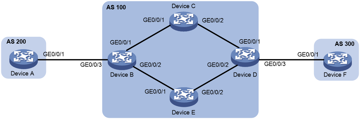
Table 1 Interface and IP address assignment
|
Device |
Interface |
IP address |
Device |
Interface |
IP address |
|
Device A |
GE1/0/1 |
120.1.0.1/24 |
Device D |
GE1/0/1 |
10.2.0.101/24 |
|
Device B |
GE1/0/1 |
10.1.0.101/24 |
|
GE1/0/2 |
13.1.1.101/24 |
|
|
GE1/0/2 |
192.168.0.101/24 |
|
GE1/0/3 |
120.2.0.2/24 |
|
|
GE1/0/3 |
120.1.0.2/24 |
Device E |
GE1/0/1 |
192.168.0.102/24 |
|
Device C |
GE1/0/1 |
10.1.0.102/24 |
|
GE1/0/2 |
13.1.1.102/24 |
|
|
GE1/0/2 |
10.2.0.102/24 |
Device F |
GE1/0/1 |
120.2.0.1/24 |
Analysis
To meet the network requirements, you must perform the following tasks:
· Configure the link Device B<—>Device C<—>Device D as the primary link:
¡ On Device B, set the local preference to 200 for the path Device D—>Device C—>Device B. The path Device D—>Device E—>Device B uses the default local preference 100.
¡ On Device D, set the local preference to 200 for the path Device B—>Device C—>Device D. The path Device B—>Device E—>Device D uses the default local preference 100.
· Set a higher preference for IBGP routes to ensure that IBGP routes rather than OSPF external routes are used in AS 100.
Software versions used
This configuration example was created and verified on R9141P16 of the MSR2630E-X1 device.
Procedures
Configuring IP addresses
# Configure an IP address for GigabitEthernet 1/0/1.
<DeviceA> system-view
[DeviceA] interface gigabitethernet 1/0/1
[DeviceA-GigabitEthernet1/0/1] ip address 120.1.0.1 24
[DeviceA-GigabitEthernet1/0/1] quit
# Configure IP addresses for other interfaces. (Details not shown.)
Configuring OSPF
# Configure Device B:
<DeviceB> system-view
[DeviceB] ospf 1
[DeviceB-ospf-1] import-route direct
[DeviceB-ospf-1] area 0
[DeviceB-ospf-1-area-0.0.0.0] network 10.1.0.0 0.0.0.255
[DeviceB-ospf-1-area-0.0.0.0] network 192.168.0.0 0.0.0.255
[DeviceB-ospf-1-area-0.0.0.0] quit
[DeviceB-ospf-1] quit
# Configure Device C:
<DeviceC> system-view
[DeviceC] ospf 1
[DeviceC-ospf-1] area 0
[DeviceC-ospf-1-area-0.0.0.0] network 10.1.0.0 0.0.0.255
[DeviceC-ospf-1-area-0.0.0.0] network 10.2.0.0 0.0.0.255
[DeviceC-ospf-1-area-0.0.0.0] quit
[DeviceC-ospf-1] quit
# Configure Device D:
<DeviceD> system-view
[DeviceD] ospf 1
[DeviceD-ospf-1] import-route direct
[DeviceD-ospf-1] area 0
[DeviceD-ospf-1-area-0.0.0.0] network 10.2.0.0 0.0.0.255
[DeviceD-ospf-1-area-0.0.0.0] network 13.1.1.0 0.0.0.255
[DeviceD-ospf-1-area-0.0.0.0] quit
[DeviceD-ospf-1] quit
# Configure Device E:
<DeviceE> system-view
[DeviceE] ospf 1
[DeviceE-ospf-1] area 0
[DeviceE-ospf-1-area-0.0.0.0] network 13.1.1.0 0.0.0.255
[DeviceE-ospf-1-area-0.0.0.0] network 192.168.0.0 0.0.0.255
[DeviceE-ospf-1-area-0.0.0.0] quit
[DeviceE-ospf-1] quit
Configuring BGP
1. Configure Device A:
# Enable BGP, set the local AS number to 200, and set the router ID for BGP to 1.1.1.1.
<DeviceA> system-view
[DeviceA] bgp 200
[DeviceA-bgp] router-id 1.1.1.1
# Establish an EBGP connection with Device B.
[DeviceA-bgp] peer 120.1.0.2 as-number 100
# Create the BGP IPv4 unicast address family and enter its view.
[DeviceA-bgp] address-family ipv4 unicast
# Enable Device A to exchange IPv4 unicast routing information with peer 120.1.0.2.
[DeviceA-bgp-ipv4] peer 120.1.0.2 enable
# Inject network 120.1.0.0/24 to the BGP routing table.
[DeviceA-bgp-ipv4] network 120.1.0.0 255.255.255.0
[DeviceA-bgp-ipv4] quit
[DeviceA-bgp] quit
2. Configure Device B:
# Enable BGP, set the local AS number to 100, and set the router ID for BGP to 2.2.2.2.
<DeviceB> system-view
[DeviceB] bgp 100
[DeviceB-bgp] router-id 2.2.2.2
# Establish an EBGP connection with Device A.
[DeviceB-bgp] peer 120.1.0.1 as-number 200
# Establish IBGP connections with Device D.
[DeviceB-bgp] peer 10.2.0.101 as-number 100
[DeviceB-bgp] peer 13.1.1.101 as-number 100
# Create the BGP IPv4 unicast address family and enter its view.
[DeviceB-bgp] address-family ipv4 unicast
# Enable Device B to exchange IPv4 unicast routing information with peer 10.2.0.101.
[DeviceB-bgp-ipv4] peer 10.2.0.101 enable
# Specify Device B as the next hop for routes sent to peer 10.2.0.101.
[DeviceB-bgp-ipv4] peer 10.2.0.101 next-hop-local
# Enable Device B to exchange IPv4 unicast routing information with peer 13.1.1.101.
[DeviceB-bgp-ipv4] peer 13.1.1.101 enable
# Specify Device B as the next hop for routes sent to peer 13.1.1.101.
[DeviceB-bgp-ipv4] peer 13.1.1.101 next-hop-local
# Enable Device B to exchange IPv4 unicast routing information with peer 120.1.0.1.
[DeviceB-bgp-ipv4] peer 120.1.0.1 enable
[DeviceB-bgp-ipv4] quit
[DeviceB-bgp] quit
3. Configure Device D:
# Enable BGP, set the local AS number to 100, and set the router ID for BGP to 4.4.4.4.
<DeviceD> system-view
[DeviceD] bgp 100
[DeviceD-bgp] router-id 4.4.4.4
# Establish IBGP connections with Device B.
[DeviceD-bgp] peer 10.1.0.101 as-number 100
[DeviceD-bgp] peer 192.168.0.101 as-number 100
# Establish an EBGP connection with Device F.
[DeviceD-bgp] peer 120.2.0.1 as-number 300
# Create the BGP IPv4 unicast address family and enter its view.
[DeviceD-bgp] address-family ipv4 unicast
# Enable Device D to exchange IPv4 unicast routing information with peer 10.1.0.101.
[DeviceD-bgp-ipv4] peer 10.1.0.101 enable
# Specify Device D as the next hop for routes sent to peer 10.1.0.101.
[DeviceD-bgp-ipv4] peer 10.1.0.101 next-hop-local
# Enable Device D to exchange IPv4 unicast routing information with peer 192.168.0.101.
[DeviceD-bgp-ipv4] peer 192.168.0.101 enable
# Specify Device D as the next hop for routes sent to peer 192.168.0.101.
[DeviceD-bgp-ipv4] peer 192.168.0.101 next-hop-local
# Enable Device D to exchange IPv4 unicast routing information with peer 120.2.0.1.
[DeviceD-bgp-ipv4] peer 120.2.0.1 enable
[DeviceD-bgp-ipv4] quit
[DeviceD-bgp] quit
4. Configure Device F:
# Enable BGP, set the local AS number to 300, and set the router ID for BGP to 6.6.6.6.
[DeviceF] bgp 300
[DeviceF-bgp] router-id 6.6.6.6
# Establish an EBGP connection with Device D.
[DeviceF-bgp] peer 120.2.0.2 as-number 100
# Create the BGP IPv4 unicast address family and enter its view.
[DeviceF-bgp] address-family ipv4 unicast
# Inject network 120.2.0.0/24 to the BGP routing table.
[DeviceF-bgp-ipv4] network 120.2.0.0 255.255.255.0
# Enable Device F to exchange IPv4 unicast routing information with peer 120.2.0.2.
[DeviceF-bgp-ipv4] peer 120.2.0.2 enable
[DeviceF-bgp-ipv4] quit
[DeviceF-bgp] quit
5. Verify BGP peer information on Device B.
[DeviceB] display bgp peer ipv4
BGP local router ID: 2.2.2.2
Local AS number: 100
Total number of peers: 3 Peers in established state: 3
Peer AS MsgRcvd MsgSent OutQ PrefRcv Up/Down State
10.2.0.101 100 6 4 0 1 00:00:56 Established
13.1.1.101 100 6 5 0 1 00:00:56 Established
120.1.0.1 200 6 5 0 1 00:00:56 Established
The output shows that Device B has established two IBGP connections with Device D, and an EBGP connection with Device A. The connections are all in Established state.
6. Test the network connectivity between Device A and Device F.
[DeviceA] ping 120.2.0.1
Ping 120.2.0.1 (120.2.0.1): 56 data bytes, press CTRL_C to break
56 bytes from 120.2.0.1: icmp_seq=0 ttl=252 time=1.189 ms
56 bytes from 120.2.0.1: icmp_seq=1 ttl=252 time=1.095 ms
56 bytes from 120.2.0.1: icmp_seq=2 ttl=252 time=1.086 ms
56 bytes from 120.2.0.1: icmp_seq=3 ttl=252 time=1.097 ms
56 bytes from 120.2.0.1: icmp_seq=4 ttl=252 time=1.089 ms
--- Ping statistics for 120.2.0.1 ---
5 packet(s) transmitted, 5 packet(s) received, 0.0% packet loss
round-trip min/avg/max/std-dev = 1.086/1.111/1.189/0.039 ms
Configuring routing policies
1. Configure Device B:
# Configure ACL 2000 to permit route 120.1.0.0/24.
[DeviceB] acl number 2000
[DeviceB-acl-basic-2000] rule permit source 120.1.0.0 0.0.0.255
[DeviceB-acl-basic-2000] quit
# Configure routing policy local-pre to set the local preference to 200 for route 120.1.0.0/24. Apply routing policy local-pre to routes outgoing to peer 10.2.0.101.
[DeviceB] route-policy local-pre permit node 10
[DeviceB-route-policy-local-pre-10] if-match ip address acl 2000
[DeviceB-route-policy-local-pre-10] apply local-preference 200
[DeviceB-route-policy-local-pre-10] quit
[DeviceB] bgp 100
[DeviceB-bgp] address-family ipv4 unicast
[DeviceB-bgp-ipv4] peer 10.2.0.101 route-policy local-pre export
# Set the preference for IBGP routes to 100 (higher than the default preference of OSPF external routes 150).
[DeviceB-bgp-ipv4] preference 255 100 130
[DeviceB-bgp-ipv4] quit
[DeviceB-bgp] quit
2. Configure Device D:
# Configure ACL 2000 to permit route 120.2.0.0/24.
[DeviceD] acl number 2000
[DeviceD-acl-basic-2000] rule permit source 120.2.0.0 0.0.0.255
[DeviceD-acl-basic-2000] quit
# Configure routing policy local-pre to set the local preference to 200 for route 120.2.0.0/24. Apply routing policy local-pre to routes outgoing to peer 10.1.0.101.
[DeviceD] route-policy local-pre permit node 10
[DeviceD-route-policy-local-pre-10] if-match ip address acl 2000
[DeviceD-route-policy-local-pre-10] apply local-preference 200
[DeviceD-route-policy-local-pre-10] quit
[DeviceD] bgp 100
[DeviceD-bgp] address-family ipv4 unicast
[DeviceD-bgp-ipv4] peer 10.1.0.101 route-policy local-pre export
# Set the preference for IBGP routes to 100 (higher than the default preference of OSPF external routes 150).
[DeviceD-bgp-ipv4] preference 255 100 130
[DeviceD-bgp-ipv4] quit
[DeviceD-bgp] quit
Verifying the configuration
# On Device B, display the BGP routing table.
[DeviceB] display bgp routing-table ipv4
Total number of routes: 3
BGP local router ID is 2.2.2.2
Status codes: * - valid, > - best, d - dampened, h - history,
s - suppressed, S - stale, i - internal, e - external
Origin: i - IGP, e - EGP, ? - incomplete
Network NextHop MED LocPrf PrefVal Path/Ogn
* >e 120.1.0.0/24 120.1.0.1 0 0 200i
* >i 120.2.0.0/24 10.2.0.101 0 200 0 300i
* i 13.1.1.101 0 100 0 300i
The output shows that Device B has two routes to 120.2.0.0/24 with local preferences 100 and 200.
# Trace the path that traffic traverses from Device A to Device F. (To use the tracert command, execute the ip ttl-expires enable command on devices between the source and destination devices, and execute the ip unreachables enable command on the destination device.)
[DeviceA] tracert 120.2.0.1
traceroute to 120.2.0.1 (120.2.0.1), 30 hops at most, 52 bytes each packet, press CTRL_C to break
1 120.1.0.2 (120.1.0.2) 2.208 ms 1.119 ms 1.085 ms
2 10.1.0.102 (10.1.0.102) 1.083 ms 1.100 ms 1.085 ms
3 10.2.0.101 (10.2.0.101) 2.364 ms 1.099 ms 1.086 ms
4 120.2.0.1 (120.2.0.1) 3.825 ms 3.693 ms 4.008 ms
The output shows that traffic is forwarded along the path Device A—>Device B—>Device C—>Device D—>Device F.
# When the primary link fails, display the BGP routing table on Device B.
[DeviceB] display bgp routing-table ipv4
Total number of routes: 2
BGP local router ID is 2.2.2.2
Status codes: * - valid, > - best, d - dampened, h - history,
s - suppressed, S - stale, i - internal, e - external
Origin: i - IGP, e - EGP, ? - incomplete
Network NextHop MED LocPrf PrefVal Path/Ogn
* >e 120.1.0.0/24 120.1.0.1 0 0 200i
* >i 120.2.0.0/24 13.1.1.101 0 100 0 300i
The output shows that Device B has one route to 120.2.0.0/24.
# Trace the path that traffic traverses from Device A to Device F.
[DeviceA] tracert 120.2.0.1
traceroute to 120.2.0.1 (120.2.0.1), 30 hops at most, 52 bytes each packet, press CTRL_C to break
1 120.1.0.2 (120.1.0.2) 2.308 ms 1.127 ms 1.091 ms
2 192.168.0.102 (192.168.0.102) 1.086 ms 1.102 ms 1.096 ms
3 13.1.1.101 (13.1.1.101) 2.451 ms 2.087 ms 1.092 ms
4 120.2.0.1 (120.2.0.1) 3.533 ms 3.818 ms 4.002 ms
The output shows that traffic is forwarded along the path Device A—>Device B—>Device E—>Device D—>Device F.
Configuration files
Device A
#
interface GigabitEthernet1/0/1
port link-mode route
ip address 120.1.0.1 255.255.255.0
#
bgp 200
router-id 1.1.1.1
peer 120.1.0.2 as-number 100
#
address-family ipv4 unicast
network 120.1.0.0 255.255.255.0
peer 120.1.0.2 enable
#
Device B
#
ospf 1
import-route direct
area 0.0.0.0
network 10.1.0.0 0.0.0.255
network 192.168.0.0 0.0.0.255
#
interface GigabitEthernet1/0/1
port link-mode route
ip address 10.1.0.101 255.255.255.0
#
interface GigabitEthernet1/0/2
port link-mode route
ip address 192.168.0.101 255.255.255.0
#
interface GigabitEthernet1/0/3
port link-mode route
ip address 120.1.0.2 255.255.255.0
#
bgp 100
router-id 2.2.2.2
peer 10.2.0.101 as-number 100
peer 13.1.1.101 as-number 100
peer 120.1.0.1 as-number 200
#
address-family ipv4 unicast
preference 255 100 130
peer 10.2.0.101 enable
peer 10.2.0.101 next-hop-local
peer 10.2.0.101 route-policy local-pre export
peer 13.1.1.101 enable
peer 13.1.1.101 next-hop-local
peer 120.1.0.1 enable
#
route-policy local-pre permit node 10
if-match ip address acl 2000
apply local-preference 200
#
acl number 2000
rule 0 permit source 120.1.0.0 0.0.0.255
#
Device C
#
ospf 1
area 0.0.0.0
network 10.1.0.0 0.0.0.255
network 10.2.0.0 0.0.0.255
#
interface GigabitEthernet1/0/1
port link-mode route
ip address 10.1.0.102 255.255.255.0
#
interface GigabitEthernet1/0/2
port link-mode route
ip address 10.2.0.102 255.255.255.0
#
Device D
#
ospf 1
import-route direct
area 0.0.0.0
network 10.2.0.0 0.0.0.255
network 13.1.1.0 0.0.0.255
#
interface GigabitEthernet1/0/1
port link-mode route
ip address 10.2.0.101 255.255.255.0
#
interface GigabitEthernet1/0/2
port link-mode route
ip address 13.1.1.101 255.255.255.0
#
interface GigabitEthernet1/0/3
port link-mode route
ip address 120.2.0.2 255.255.255.0
#
bgp 100
router-id 4.4.4.4
peer 10.1.0.101 as-number 100
peer 120.2.0.1 as-number 300
peer 192.168.0.101 as-number 100
#
address-family ipv4 unicast
preference 255 100 130
peer 10.1.0.101 enable
peer 10.1.0.101 next-hop-local
peer 10.1.0.101 route-policy local-pre export
peer 192.168.0.101 enable
peer 192.168.0.101 next-hop-local
peer 120.2.0.1 enable
#
route-policy local-pre permit node 10
if-match ip address acl 2000
apply local-preference 200
#
#
acl number 2000
rule 0 permit source 120.2.0.0 0.0.0.255
#
Device E
#
ospf 1
area 0.0.0.0
network 13.1.1.0 0.0.0.255
network 192.168.0.0 0.0.0.255
#
interface GigabitEthernet1/0/1
port link-mode route
ip address 192.168.0.102 255.255.255.0
#
interface GigabitEthernet1/0/2
port link-mode route
ip address 13.1.1.102 255.255.255.0
#
Device F
#
interface GigabitEthernet1/0/1
port link-mode route
ip address 120.2.0.1 255.255.255.0
#
bgp 300
router-id 6.6.6.6
peer 120.2.0.2 as-number 100
#
address-family ipv4 unicast
network 120.2.0.0 255.255.255.0
peer 120.2.0.2 enable
#
Related documentation
· Layer 3—IP Routing Configuration Guide in H3C MSR1000[2600][3600] Routers Configuration Guides(V9)
· Layer 3—IP Routing Command Reference in H3C MSR1000[2600][3600] Routers Configuration Guides(V9)