- Table of Contents
-
- H3C MSR1000[2600][3600] Routers Configuration Examples All-in-One-R9141-6W100
- 00-Preface
- 01-Local 802.1X Authentication Configuration Examples
- 02-RADIUS-Based 802.1X Authentication Configuration Examples
- 03-AAA Configuration Examples
- 04-ACL Configuration Examples
- 05-MPLS over ADVPN Configuration Examples
- 06-ARP Attack Protection Configuration Examples
- 07-BFD Configuration Examples
- 08-Basic BGP Configuration Examples
- 09-BGP Route Attribute-Based Route Selection Configuration Examples
- 10-EAA Monitor Policy Configuration Examples
- 11-GRE with OSPF Configuration Examples
- 12-HoVPN Configuration Examples
- 13-IGMP Snooping Configuration Examples
- 14-IGMP Configuration Examples
- 15-IPsec Configuration Examples
- 16-IPsec Digital Certificate Authentication Configuration Examples
- 17-IPv6 IS-IS Configuration Examples
- 18-IPv6 over IPv4 GRE Tunnel Configuration Examples
- 19-IPv6 over IPv4 Manual Tunnel with OSPFv3 Configuration Examples
- 20-IS-IS Configuration Examples
- 21-Combined ISATAP Tunnel and 6to4 Tunnel Configuration Examples
- 22-L2TP over IPsec Configuration Examples
- 23-Multi-Instance L2TP Configuration Examples
- 24-L2TP Multidomain Access Configuration Examples
- 25-MPLS L3VPN Configuration Examples
- 26-MPLS OAM Configuration Examples
- 27-MPLS TE Configuration Examples
- 28-Basic MPLS Configuration Examples
- 29-NAT DNS Mapping Configuration Examples
- 30-NetStream Configuration Examples
- 31-NQA Configuration Examples
- 32-NTP Configuration Examples
- 33-OSPFv3 Configuration Examples
- 34-OSPF Configuration Examples
- 35-OSPF Multi-Process Configuration Examples
- 36-OSPF Multi-Instance Configuration Examples
- 37-Portal Configuration Examples
- 38-PPP Configuration Examples
- 39-RBAC Configuration Examples
- 40-RMON Configuration Examples
- 41-IPv4 NetStream Sampling Configuration Examples
- 42-SNMP Configuration Examples
- 43-SRv6 Configuration Examples
- 44-SSH Configuration Examples
- 45-Tcl Commands Configuration Examples
- 46-VLAN Configuration Examples
- 47-VRRP Configuration Examples
- 48-VXLAN over IPsec Configuration Examples
- 49-WLAN AC Configuration Examples
- 50-Small and Medium-Sized Store Configuration Examples
- 51-Cloudnet VPN Configuration Examples
- 52-Ethernet Link Aggregation Configuration Examples
- 53-Ethernet OAM Configuration Examples
- 54-Outbound Bidirectional NAT Configuration Examples
- 55-NAT Hairpin in C-S Mode Configuration Examples
- 56-Load Sharing NAT Server Configuration Examples
- 57-BIDIR-PIM Configuration Examples
- 58-Control Plane-Based QoS Policy Configuration Examples
- 59-Scheduling a Task Configuration Examples
- 60-Client-Initiated L2TP Tunnel Configuration Examples
- 61-LAC-Auto-Initiated L2TP Tunnel Configuration Examples
- 62-Authorized ARP Configuration Examples
- 63-GTS Configuration Examples
- 64-Traffic Policing Configuration Examples
- 65-Traffic Accounting Configuration Examples
- 66-Mobile Communication Modem Management Configuration Examples
- 67-Port Isolation Configuration Examples
- 68-PBR Configuration Examples
- 69-TFTP Client Software Upgrade Configuration Examples
- 70-FTP Client Software Upgrade Configuration Examples
- 71-FTP Server Software Upgrade Configuration Examples
- 72-Routing Policy Configuration Examples
- 73-Software Upgrade from the BootWare Menu Configuration Examples
- 74-Mirroring Configuration Examples
- Related Documents
-
| Title | Size | Download |
|---|---|---|
| 18-IPv6 over IPv4 GRE Tunnel Configuration Examples | 107.11 KB |
|
|
|
H3C Routers |
|
IPv6 over IPv4 GRE Tunnel Configuration Examples |
|
|
|
|
Copyright © 2024 New H3C Technologies Co., Ltd. All rights reserved.
No part of this manual may be reproduced or transmitted in any form or by any means without prior written consent of New H3C Technologies Co., Ltd.
Except for the trademarks of New H3C Technologies Co., Ltd., any trademarks that may be mentioned in this document are the property of their respective owners.
The information in this document is subject to change without notice.
Introduction
The following information provides IPv6 over IPv4 GRE configuration examples.
Prerequisites
The following information applies to Comware 9-based routers. Procedures and information in the examples might be slightly different depending on the software or hardware version of the routers.
The configuration examples were created and verified in a lab environment, and all the devices were started with the factory default configuration. When you are working on a live network, make sure you understand the potential impact of every command on your network.
This document assumes that you have basic knowledge of IPv6 over IPv4 GRE.
Example: Configuring an IPv6 over IPv4 GRE tunnel
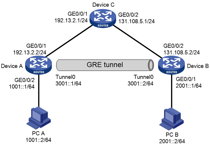
Network configuration
As shown in Figure 1, Device A, Device B, and Device C are connected to each other through the IPv4 network. Device A and Device B are connected to IPv6 hosts PC A and PC B, respectively.
Configure a GRE tunnel between the two border dual-stack devices (Device A and Device B) to allow the two IPv6 PCs to communicate with each other over the IPv4 network.
Analysis
· To allow the two IPv6 PCs to communicate over the IPv4 network, configure the GRE tunnel mode as GRE/IPv4 (GRE over IPv4) and assign an IPv6 address to the GRE tunnel interface.
· To direct traffic sent from PC A to PC B to the GRE tunnel, configure a route reaching the destination network through the tunnel on Device A. Configure the route destination address as the packet destination address before GRE encapsulation (IPv6 address of PC B) and next hop address as the tunnel interface address on the tunnel remote device Device B, or specify the route's outgoing interface as the local GRE tunnel interface. You can configure this route by configuring a static route or configuring a dynamic routing protocol on both the tunnel interface and the Layer 3 interface connecting PC A. This example uses a static route. The corresponding configuration is also required on Device B.
· To ensure that the two ends of the GRE tunnel can reach other through IPv4, configure a static route to the peer on Device A and Device B, respectively.
Software versions used
This configuration example was created and verified on R9141P16 of the MSR2630E-X1 device.
Restrictions and guidelines
You must configure the tunnel source address and destination address at both ends of a tunnel. The tunnel source or destination address at one end must be the tunnel destination or source address at the other end.
Procedures
Configuring Device A
# Assign an IPv6 address to interface GigabitEthernet 1/0/1.
<DeviceA> system-view
[DeviceA] interface gigabitethernet 1/0/1
[DeviceA-GigabitEthernet1/0/1] ipv6 address 1001::1 64
[DeviceA-GigabitEthernet1/0/1] quit
# Assign IP addresses to other interfaces on Device A in the same way. (Details not shown.)
Create tunnel interface Tunnel 0, and specify the GRE/IPv4 tunnel mode.
[DeviceA] interface tunnel 0 mode gre
# Assign an IPv6 address to the tunnel interface.
[DeviceA-Tunnel0] ipv6 address 3001::1 64
# Configure the source address of the tunnel.
[DeviceA-Tunnel0] source 192.13.2.2
# Configure the destination address of the tunnel.
[DeviceA-Tunnel0] destination 131.108.5.2
[DeviceA-Tunnel0] quit
# Configure a static route from Device A through Tunnel 0 to PC B.
[DeviceA] ipv6 route-static 2001::2 64 tunnel 0
# Configure a static route from Device A to the tunnel remote end (Device B).
[DeviceA] ip route-static 131.108.5.0 255.255.255.0 192.13.2.1
Configuring Device B
# Assign an IPv6 address to interface GigabitEthernet 1/0/2.
<DeviceB> system-view
[DeviceB] interface gigabitethernet 1/0/2
[DeviceB-GigabitEthernet1/0/2] ipv6 address 2001::1 64
[DeviceB-GigabitEthernet1/0/2] quit
# Assign IP addresses to other interfaces on Device B in the same way. (Details not shown.)
Create tunnel interface Tunnel 0, and specify the GRE/IPv4 tunnel mode.
[DeviceB] interface tunnel 0 mode gre
# Assign an IPv6 address to the tunnel interface.
[DeviceB-Tunnel0] ipv6 address 3001::2 64
# Configure the source address of the tunnel.
[DeviceB-Tunnel0] source 131.108.5.2
# Configure the destination address of the tunnel.
[DeviceB-Tunnel0] destination 192.13.2.2
[DeviceB-Tunnel0] quit
# Configure a static route from Device B through Tunnel 0 to PC A.
[DeviceB] ipv6 route-static 1001::2 64 Tunnel 0
# Configure a static route from Device B to the tunnel remote end (Device A).
[DeviceB] ip route-static 192.13.2.0 255.255.255.0 131.108.5.1
Configuring Device C
# Assign an IPv6 address to interface GigabitEthernet 1/0/1.
<DeviceC> system-view
[DeviceC] interface gigabitethernet 1/0/1
[DeviceC-GigabitEthernet1/0/1] ip address 192.13.2.1 24
[DeviceC-GigabitEthernet1/0/1] quit
# Assign an IPv6 address to interface GigabitEthernet 1/0/2.
[DeviceC] interface gigabitethernet 1/0/2
[DeviceC-GigabitEthernet1/0/2] ip address 131.108.5.1 24
[DeviceC-GigabitEthernet1/0/2] quit
Verifying the configuration
PC A and PC B can ping each other.
C:\>ping6 2001::2
Pinging 2001::2
from 1001::1 with 32 bytes of data:
Reply from 2001::2: bytes=32 time<1ms
Reply from 2001::2: bytes=32 time<1ms
Reply from 2001::2: bytes=32 time<1ms
Reply from 2001::2: bytes=32 time<1ms
Ping statistics for 2001::2:
Packets: Sent = 4, Received = 4, Lost = 0 (0% loss),
Approximate round trip times in milli-seconds:
Minimum = 0ms, Maximum = 0ms, Average = 0ms
Configuration files
Device A
#
interface GigabitEthernet1/0/1
port link-mode route
ip address 192.13.2.2 255.255.255.0
#
interface GigabitEthernet1/0/1
port link-mode route
ipv6 address 1001::1/64
#
interface Tunnel0 mode gre
ipv6 address 3001::1/64
source 192.13.2.2
destination 131.108.5.2
#
ip route-static 131.108.5.0 255.255.255.0 192.13.2.1
#
ipv6 route-static 2001::2 64 Tunnel 0
#
Device B
#
interface GigabitEthernet1/0/2
port link-mode route
ip address 131.108.5.2 255.255.255.0
#
interface GigabitEthernet1/0/2
port link-mode route
ipv6 address 2001::1/64
#
interface Tunnel0 mode gre
ipv6 address 3001::2/64
source 131.108.5.2
destination 192.13.2.2
#
ip route-static 192.13.2.0 255.255.255.0 131.108.5.1
#
ipv6 route-static 1001::2 64 Tunnel 0
#
Device C
#
interface GigabitEthernet1/0/1
port link-mode route
ip address 192.13.2.1 255.255.255.0
#
interface GigabitEthernet1/0/2
port link-mode route
ip address 131.108.5.1 255.255.255.0
#
Related documentation
· IP Tunneling and Security VPN Configuration Guide in H3C MSR1000[2600][3600] Routers Configuration Guides(V9)
· IP Tunneling and Security VPN Command Reference in H3C MSR1000[2600][3600] Routers Command References(V9)