- Table of Contents
-
- H3C MSR1000[2600][3600] Routers Configuration Examples All-in-One-R9141-6W100
- 00-Preface
- 01-Local 802.1X Authentication Configuration Examples
- 02-RADIUS-Based 802.1X Authentication Configuration Examples
- 03-AAA Configuration Examples
- 04-ACL Configuration Examples
- 05-MPLS over ADVPN Configuration Examples
- 06-ARP Attack Protection Configuration Examples
- 07-BFD Configuration Examples
- 08-Basic BGP Configuration Examples
- 09-BGP Route Attribute-Based Route Selection Configuration Examples
- 10-EAA Monitor Policy Configuration Examples
- 11-GRE with OSPF Configuration Examples
- 12-HoVPN Configuration Examples
- 13-IGMP Snooping Configuration Examples
- 14-IGMP Configuration Examples
- 15-IPsec Configuration Examples
- 16-IPsec Digital Certificate Authentication Configuration Examples
- 17-IPv6 IS-IS Configuration Examples
- 18-IPv6 over IPv4 GRE Tunnel Configuration Examples
- 19-IPv6 over IPv4 Manual Tunnel with OSPFv3 Configuration Examples
- 20-IS-IS Configuration Examples
- 21-Combined ISATAP Tunnel and 6to4 Tunnel Configuration Examples
- 22-L2TP over IPsec Configuration Examples
- 23-Multi-Instance L2TP Configuration Examples
- 24-L2TP Multidomain Access Configuration Examples
- 25-MPLS L3VPN Configuration Examples
- 26-MPLS OAM Configuration Examples
- 27-MPLS TE Configuration Examples
- 28-Basic MPLS Configuration Examples
- 29-NAT DNS Mapping Configuration Examples
- 30-NetStream Configuration Examples
- 31-NQA Configuration Examples
- 32-NTP Configuration Examples
- 33-OSPFv3 Configuration Examples
- 34-OSPF Configuration Examples
- 35-OSPF Multi-Process Configuration Examples
- 36-OSPF Multi-Instance Configuration Examples
- 37-Portal Configuration Examples
- 38-PPP Configuration Examples
- 39-RBAC Configuration Examples
- 40-RMON Configuration Examples
- 41-IPv4 NetStream Sampling Configuration Examples
- 42-SNMP Configuration Examples
- 43-SRv6 Configuration Examples
- 44-SSH Configuration Examples
- 45-Tcl Commands Configuration Examples
- 46-VLAN Configuration Examples
- 47-VRRP Configuration Examples
- 48-VXLAN over IPsec Configuration Examples
- 49-WLAN AC Configuration Examples
- 50-Small and Medium-Sized Store Configuration Examples
- 51-Cloudnet VPN Configuration Examples
- 52-Ethernet Link Aggregation Configuration Examples
- 53-Ethernet OAM Configuration Examples
- 54-Outbound Bidirectional NAT Configuration Examples
- 55-NAT Hairpin in C-S Mode Configuration Examples
- 56-Load Sharing NAT Server Configuration Examples
- 57-BIDIR-PIM Configuration Examples
- 58-Control Plane-Based QoS Policy Configuration Examples
- 59-Scheduling a Task Configuration Examples
- 60-Client-Initiated L2TP Tunnel Configuration Examples
- 61-LAC-Auto-Initiated L2TP Tunnel Configuration Examples
- 62-Authorized ARP Configuration Examples
- 63-GTS Configuration Examples
- 64-Traffic Policing Configuration Examples
- 65-Traffic Accounting Configuration Examples
- 66-Mobile Communication Modem Management Configuration Examples
- 67-Port Isolation Configuration Examples
- 68-PBR Configuration Examples
- 69-TFTP Client Software Upgrade Configuration Examples
- 70-FTP Client Software Upgrade Configuration Examples
- 71-FTP Server Software Upgrade Configuration Examples
- 72-Routing Policy Configuration Examples
- 73-Software Upgrade from the BootWare Menu Configuration Examples
- 74-Mirroring Configuration Examples
- Related Documents
-
| Title | Size | Download |
|---|---|---|
| 35-OSPF Multi-Process Configuration Examples | 74.49 KB |
OSPF Multi-Process Configuration Examples
Copyright © 2024 New H3C Technologies Co., Ltd. All rights reserved.
No part of this manual may be reproduced or transmitted in any form or by any means without prior written consent of New H3C Technologies Co., Ltd.
Except for the trademarks of New H3C Technologies Co., Ltd., any trademarks that may be mentioned in this document are the property of their respective owners.
The information in this document is subject to change without notice.
Example: Configuring the OSPF multi-process feature
Network configuration
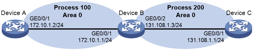
As shown in Figure 1, Device A and Device B establish a neighbor relationship in OSPF process 100, and Device B and Device C establish a neighbor relationship in OSPF process 200. Device A and Device C cannot learn routes from each other through OSPF.
Software versions used
This configuration example was created and verified on R9141P16 of the MSR2630E-X1 device.
Procedures
Configuring Device A
# Specify DeviceA as the device name.
<Sysname> system-view
[Sysname] sysname DeviceA
# Enable OSPF process 100 and enable OSPF on interfaces whose primary IP address is on network 172.10.1.0/24.
[DeviceA] ospf 100 router-id 1.1.1.9
[DeviceA-ospf-100] area 0.0.0.0
[DeviceA-ospf-100-area-0.0.0.0] network 172.10.1.0 0.0.0.255
[DeviceA-ospf-100-area-0.0.0.0] quit
[DeviceA-ospf-100] quit
Configuring Device B
# Specify DeviceB as the device name.
<Sysname> system-view
[Sysname] sysname DeviceB
# Enable OSPF process 100 and enable OSPF on interfaces whose primary IP address is on network 172.10.1.0/24.
[DeviceB] ospf 100 router-id 2.2.2.9
[DeviceB-ospf-100] area 0.0.0.0
[DeviceB-ospf-100-area-0.0.0.0] network 172.10.1.0 0.0.0.255
[DeviceB-ospf-100-area-0.0.0.0] quit
[DeviceB-ospf-100] quit
# Enable OSPF process 200 and enable OSPF on interfaces whose primary IP address is on network 131.108.1.0/24.
[DeviceB] ospf 200 router-id 2.2.2.9
[DeviceB-ospf-200] area 0.0.0.0
[DeviceB-ospf-200-area-0.0.0.0] network 131.108.1.0 0.0.0.255
[DeviceB-ospf-200-area-0.0.0.0] quit
[DeviceB-ospf-200] quit
Configuring Device C
# Specify DeviceC as the device name.
<Sysname> system-view
[Sysname] sysname DeviceC
# Enable OSPF process 200 and enable OSPF on interfaces whose primary IP address is on network 131.108.1.0/24.
[DeviceC] ospf 200 router-id 3.3.3.9
[DeviceC-ospf-200] area 0.0.0.0
[DeviceC-ospf-200-area-0.0.0.0] network 131.108.1.0 0.0.0.255
[DeviceC-ospf-200-area-0.0.0.0] quit
[DeviceC-ospf-200] quit
Verifying the configuration
# Execute the display ospf peer command on Device B to verify that it has established a neighbor relationship with Device A and Device C separately.
[DeviceB] display ospf peer
OSPF Process 100 with Router ID 2.2.2.9
Neighbor Brief Information
Area: 0.0.0.0
Router ID Address Pri Dead-Time State Interface
1.1.1.9 172.10.1.1 1 30 Full/DR GE1/0/1
OSPF Process 200 with Router ID 2.2.2.9
Neighbor Brief Information
Area: 0.0.0.0
Router ID Address Pri Dead-Time State Interface
3.3.3.9 131.108.1.1 1 39 Full/BDR GE1/0/2
# Execute the display ip routing-table command on Device A to verify that Device A does not have a route to 131.108.1.0/24.
[DeviceA] display ip routing-table
Destinations : 11 Routes : 11
Destination/Mask Proto Pre Cost NextHop Interface
0.0.0.0/32 Direct 0 0 127.0.0.1 InLoop0
1.1.1.9/32 Direct 0 0 127.0.0.1 InLoop0
127.0.0.0/8 Direct 0 0 127.0.0.1 InLoop0
127.0.0.0/32 Direct 0 0 127.0.0.1 InLoop0
127.0.0.1/32 Direct 0 0 127.0.0.1 InLoop0
127.255.255.255/32 Direct 0 0 127.0.0.1 InLoop0
172.10.1.0/24 Direct 0 0 172.10.1.1 GE1/0/1
172.10.1.0/32 Direct 0 0 172.10.1.1 GE1/0/1
172.10.1.1/32 Direct 0 0 127.0.0.1 InLoop0
172.10.1.255/32 Direct 0 0 172.10.1.1 GE1/0/1
255.255.255.255/32 Direct 0 0 127.0.0.1 InLoop0
# Execute the display ip routing-table command on Device C to verify that Device C does not have a route to 172.10.1.0/24.
# Execute the display ip routing-table command on Device C.
Destinations : 11 Routes : 11
Destination/Mask Proto Pre Cost NextHop Interface
0.0.0.0/32 Direct 0 0 127.0.0.1 InLoop0
3.3.3.9/32 Direct 0 0 127.0.0.1 InLoop0
127.0.0.0/8 Direct 0 0 127.0.0.1 InLoop0
127.0.0.0/32 Direct 0 0 127.0.0.1 InLoop0
127.0.0.1/32 Direct 0 0 127.0.0.1 InLoop0
127.255.255.255/32 Direct 0 0 127.0.0.1 InLoop0
131.108.1.0/24 Direct 0 0 131.108.1.1 GE1/0/2
131.108.1.0/32 Direct 0 0 131.108.1.1 GE1/0/2
131.108.1.1/32 Direct 0 0 127.0.0.1 InLoop0
131.108.1.255/32 Direct 0 0 131.108.1.1 GE1/0/2
255.255.255.255/32 Direct 0 0 127.0.0.1 InLoop0
Configuration files
Device A
#
sysname DeviceA
#
ospf 100 router-id 1.1.1.9
area 0.0.0.0
network 172.10.1.0 0.0.0.255
#
interface GigabitEthernet1/0/1
ip address 172.10.1.2 255.255.255.0
#
Device B
#
sysname DeviceB
#
ospf 100 router-id 2.2.2.9
area 0.0.0.0
network 172.10.1.0 0.0.0.255
#
ospf 200 router-id 2.2.2.9
area 0.0.0.0
network 131.108.1.0 0.0.0.255
#
#
interface GigabitEthernet1/0/1
ip address 172.10.1.1 255.255.255.0
#
interface GigabitEthernet1/0/2
ip address 131.108.1.3 255.255.255.0
#
Device C
#
sysname DeviceC
#
ospf 200 router-id 3.3.3.9
area 0.0.0.0
network 131.108.1.0 0.0.0.255
#
interface GigabitEthernet1/0/1
ip address 131.108.1.1 255.255.255.0
#
Related documentation
· Layer 3—IP Routing Configuration Guide in H3C MSR1000[2600][3600] Routers Configuration Guides(V9)
· Layer 3—IP Routing Command Reference in H3C MSR1000[2600][3600] Routers Configuration Guides(V9)