- Table of Contents
-
- H3C MSR1000[2600][3600] Routers Configuration Examples All-in-One-R9141-6W100
- 00-Preface
- 01-Local 802.1X Authentication Configuration Examples
- 02-RADIUS-Based 802.1X Authentication Configuration Examples
- 03-AAA Configuration Examples
- 04-ACL Configuration Examples
- 05-MPLS over ADVPN Configuration Examples
- 06-ARP Attack Protection Configuration Examples
- 07-BFD Configuration Examples
- 08-Basic BGP Configuration Examples
- 09-BGP Route Attribute-Based Route Selection Configuration Examples
- 10-EAA Monitor Policy Configuration Examples
- 11-GRE with OSPF Configuration Examples
- 12-HoVPN Configuration Examples
- 13-IGMP Snooping Configuration Examples
- 14-IGMP Configuration Examples
- 15-IPsec Configuration Examples
- 16-IPsec Digital Certificate Authentication Configuration Examples
- 17-IPv6 IS-IS Configuration Examples
- 18-IPv6 over IPv4 GRE Tunnel Configuration Examples
- 19-IPv6 over IPv4 Manual Tunnel with OSPFv3 Configuration Examples
- 20-IS-IS Configuration Examples
- 21-Combined ISATAP Tunnel and 6to4 Tunnel Configuration Examples
- 22-L2TP over IPsec Configuration Examples
- 23-Multi-Instance L2TP Configuration Examples
- 24-L2TP Multidomain Access Configuration Examples
- 25-MPLS L3VPN Configuration Examples
- 26-MPLS OAM Configuration Examples
- 27-MPLS TE Configuration Examples
- 28-Basic MPLS Configuration Examples
- 29-NAT DNS Mapping Configuration Examples
- 30-NetStream Configuration Examples
- 31-NQA Configuration Examples
- 32-NTP Configuration Examples
- 33-OSPFv3 Configuration Examples
- 34-OSPF Configuration Examples
- 35-OSPF Multi-Process Configuration Examples
- 36-OSPF Multi-Instance Configuration Examples
- 37-Portal Configuration Examples
- 38-PPP Configuration Examples
- 39-RBAC Configuration Examples
- 40-RMON Configuration Examples
- 41-IPv4 NetStream Sampling Configuration Examples
- 42-SNMP Configuration Examples
- 43-SRv6 Configuration Examples
- 44-SSH Configuration Examples
- 45-Tcl Commands Configuration Examples
- 46-VLAN Configuration Examples
- 47-VRRP Configuration Examples
- 48-VXLAN over IPsec Configuration Examples
- 49-WLAN AC Configuration Examples
- 50-Small and Medium-Sized Store Configuration Examples
- 51-Cloudnet VPN Configuration Examples
- 52-Ethernet Link Aggregation Configuration Examples
- 53-Ethernet OAM Configuration Examples
- 54-Outbound Bidirectional NAT Configuration Examples
- 55-NAT Hairpin in C-S Mode Configuration Examples
- 56-Load Sharing NAT Server Configuration Examples
- 57-BIDIR-PIM Configuration Examples
- 58-Control Plane-Based QoS Policy Configuration Examples
- 59-Scheduling a Task Configuration Examples
- 60-Client-Initiated L2TP Tunnel Configuration Examples
- 61-LAC-Auto-Initiated L2TP Tunnel Configuration Examples
- 62-Authorized ARP Configuration Examples
- 63-GTS Configuration Examples
- 64-Traffic Policing Configuration Examples
- 65-Traffic Accounting Configuration Examples
- 66-Mobile Communication Modem Management Configuration Examples
- 67-Port Isolation Configuration Examples
- 68-PBR Configuration Examples
- 69-TFTP Client Software Upgrade Configuration Examples
- 70-FTP Client Software Upgrade Configuration Examples
- 71-FTP Server Software Upgrade Configuration Examples
- 72-Routing Policy Configuration Examples
- 73-Software Upgrade from the BootWare Menu Configuration Examples
- 74-Mirroring Configuration Examples
- Related Documents
-
| Title | Size | Download |
|---|---|---|
| 66-Mobile Communication Modem Management Configuration Examples | 368.63 KB |
Mobile Communication Modem Management Configuration Examples
Copyright © 2024 New H3C Technologies Co., Ltd. All rights reserved
No part of this manual may be reproduced or transmitted in any form or by any means without prior written consent of New H3C Technologies Co., Ltd.
Except for the trademarks of New H3C Technologies Co., Ltd., any trademarks that may be mentioned in this document are the property of their respective owners.
The information in this document is subject to change without notice.
Contents
Example: Configuring 5G modem dialup for network access
Example: Configuring 5G modem dialup link backup
Example: Configuring 5G modem dialup and an IPsec tunnel
Example: Configuring 5G modem dialup and ADVPN tunnels
Example: Configuring 5G modem dialup and a VPDN tunnel
Example: Configuring 5G modem IPv6 dialup
Example: Configuring 5G modem dialup for network access
Software versions used
This configuration example was created and verified on R9141P16 of the MSR2630E-X1 device.
Network configuration
As shown in Figure 1, Router A has a 5G modem module. The user accesses the 5G network through auto-dial DDR and a permanent online connection is established. Configure Router A to meet the following requirements:
· Channelize Cellular 1/0 into Eth-channel interface Eth-channel 1/0:0. Use Eth-channel 1/0:0 as a DDR dialer interface and enable it to obtain an IP address by using the modem-manufacturer's proprietary protocol.
· Enable traditional DDR on Eth-channel 1/0:0 and set the dial string for placing calls based on the service provider. Typically, set the dial string for placing calls to *99# for China Mobile or China Unicom and #777 for China Telecom in China mainland.
· Configure an APN profile, and use an APN automatically assigned by the service provider.
· Configure DDR to place calls for only IPv4 packets.

Restrictions and guidelines
When a common 5G SIM card is used for network access, the router can access the 5G network after you use an APN automatically assigned by the service provider in the 5G modem profile. When a 5G IoT or VPDN SIM card is used, you must use the APN provided by the service provider in the 5G modem profile. You must also configure the authentication method for 5G network access based on the username and password provided by the service provider.
Procedures
1. Assign an IP address to the interface. (Details not shown.)
2. Configure 5G modem dialup:
# Configure a dialup rule for dialer group 1.
<RouterA> system-view
[RouterA] dialer-group 1 rule ip permit
# Configure an APN profile named dynamic1, and use an APN automatically assigned by the service provider.
[RouterA] apn-profile dynamic1
[RouterA-apn-profile-dynamic] apn dynamic
[RouterA-apn-profile-dynamic] quit
# Channelize Cellular 1/0 into an Eth-channel interface.
[RouterA] controller cellular 1/0
[RouterA-Cellular1/0] eth-channel 0
[RouterA-Cellular1/0] quit
# Enable Eth-channel1/0:0 to obtain an IP address automatically through the modem manufacturer's proprietary protocol.
[RouterA] interface eth-channel 1/0:0
[RouterA-Eth-channel1/0:0] ip address cellular-alloc
# Apply APN profile dynamic1 to Eth-channel 1/0:0.
[RouterA-Eth-channel1/0:0] apn-profile apply dynamic1
# Enable traditional DDR on Eth-channel 1/0:0 and associate Eth-channel 1/0:0 with dialer group 1.
[RouterA-Eth-channel1/0:0] dialer circular enable
[RouterA-Eth-channel1/0:0] dialer-group 1
# Set the link idle-timeout timer to 0 seconds, wait-carrier timer to 30 seconds, and auto-dial timer to 5 seconds.
[RouterA-Eth-channel1/0:0] dialer timer idle 0
[RouterA-Eth-channel1/0:0] dialer timer wait-carrier 30
[RouterA-Eth-channel1/0:0] dialer timer autodial 5
# Set the dial string for placing calls. Typically, set the dial string for placing calls to *99# for China Mobile or China Unicom and #777 for China Telecom in China mainland.
[RouterA-Eth-channel1/0:0] dialer number *99# autodial
# Configure an outbound dynamic NAT rule for Eth-channel 1/0:0.
[RouterA-Eth-channel1/0:0] nat outbound
[RouterA-Eth-channel1/0:0] quit
# Configure the default route.
[RouterA] ip route-static 0.0.0.0 0 eth-channel 1/0:0
Verifying the configuration
# Verify that the configured default route takes effect and the user can access the network through the device.
[RouterA] display ip routing-table
Destination/Mask Proto Pre Cost NextHop Interface
0.0.0.0/0 Static 60 0 0.0.0.0 E-Ch1/0:0
0.0.0.0/32 Direct 0 0 127.0.0.1 InLoop0
1.0.0.2/32 Direct 0 0 127.0.0.1 InLoop0
127.0.0.0/8 Direct 0 0 127.0.0.1 InLoop0
127.0.0.1/32 Direct 0 0 127.0.0.1 InLoop0
127.255.255.255/32 Direct 0 0 127.0.0.1 InLoop0
...
Configuration files
#
interface gigabitethernet 0/0/1
ip address 192.168.1.1 255.255.255.0
#
dialer-group 1 rule ip permit
#
apn-profile dynamic1
apn dynamic
#
controller cellular 1/0
eth-channel 0
#
interface eth-channel 1/0:0
ip address cellular-alloc
apn-profile apply dynamic1
dialer circular enable
dialer-group 1
dialer timer idle 0
dialer timer wait-carrier 30
dialer timer autodial 5
dialer number *99# autodial
nat outbound
#
ip route-static 0.0.0.0 0.0.0.0 eth-channel 1/0:0
#
Example: Configuring 5G modem dialup link backup
Software versions used
This configuration example was created and verified on R9141P16 of the MSR2630E-X1 device.
Network configuration
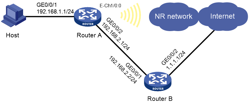
As shown in Figure 2, Router A can access the Internet via the wired link from Router A to Router B. Router A can also access the 5G network through DDR dial-up because it has a 5G modem module. Configure Router A to meet the following requirements:
· Configure traditional auto-dial DDR and establish a permanent 5G online connection.
· Configure two routes to the Internet. The wired link forwards data as the primary link, and the 5G link backs up data as the secondary link.
· Monitor the wired link state so that a link switchover can be performed immediately when the wired link state changes.
Analysis
To have the wired link serve as the primary link to forward data, configure a higher preference for the route over the wired link.
To monitor the wired link state in real time, configure NQA on Router A.
To perform a link switchover immediately upon a link state change, configure track entry association with static routes. When NQA detects a wired link failure, it automatically sets the wired link interface route to inactive. The static route of the 5G link takes effect and forwards data over the 5G network. When NQA detects that the wired link becomes normal, it automatically activates the wired link interface route. The static route of the wired link takes effect and data is forwarded through wired connection.
Restrictions and guidelines
When a common 5G SIM card is used for network access, the router can access the 5G network after you use an APN automatically assigned by the service provider in the 5G modem profile. When a 5G IoT or VPDN SIM card is used, you must use the APN provided by the service provider in the 5G modem profile. You must also configure the authentication method for 5G network access based on the username and password provided by the service provider.
Procedures
Configuring Router A
1. Assign IP addresses to interfaces. (Details not shown.)
2. Configure 5G modem dialup:
# Configure a dialup rule for dialer group 1.
<RouterA> system-view
[RouterA] dialer-group 1 rule ip permit
# Configure an APN profile named dynamic1, and use an APN automatically assigned by the service provider.
[RouterA] apn-profile dynamic1
[RouterA-apn-profile-dynamic] apn dynamic
[RouterA-apn-profile-dynamic] quit
# Channelize Cellular 1/0 into an Eth-channel interface.
[RouterA] controller cellular 1/0
[RouterA-Cellular1/0] eth-channel 0
[RouterA-Cellular1/0] quit
# Enable Eth-channel1/0:0 to obtain an IP address automatically through the modem manufacturer's proprietary protocol.
[RouterA] interface eth-channel 1/0:0
[RouterA-Eth-channel1/0:0] ip address cellular-alloc
# Apply APN profile dynamic1 to Eth-channel 1/0:0.
[RouterA-Eth-channel1/0:0] apn-profile apply dynamic1
# Enable traditional DDR on Eth-channel 1/0:0 and associate Eth-channel 1/0:0 with dialer group 1.
[RouterA-Eth-channel1/0:0] dialer circular enable
[RouterA-Eth-channel1/0:0] dialer-group 1
# Set the link idle-timeout timer to 0 seconds, wait-carrier timer to 30 seconds, and auto-dial timer to 5 seconds.
[RouterA-Eth-channel1/0:0] dialer timer idle 0
[RouterA-Eth-channel1/0:0] dialer timer wait-carrier 30
[RouterA-Eth-channel1/0:0] dialer timer autodial 5
# Set the dial string for placing calls. Typically, set the dial string for placing calls to *99# for China Mobile or China Unicom and #777 for China Telecom in China mainland.
[RouterA-Eth-channel1/0:0] dialer number *99# autodial
# Configure an outbound dynamic NAT rule for Eth-channel 1/0:0.
[RouterA-Eth-channel1/0:0] nat outbound
[RouterA-Eth-channel1/0:0] quit
# Configure the default route for the wired link with preference 50, and associate the route with a track entry. Configure the default route for the 5G link with preference 60.
[RouterA] ip route-static 0.0.0.0 0 gigabitethernet 0/0/2 192.168.2.2 track 1 preference 50
[RouterA] ip route-static 0.0.0.0 0 eth-channel 1/0:0 preference 60
3. Configure an NQA operation:
# Create an ICMP echo operation with administrator name admin and operation tag test. Specify the destination IP address as 1.1.1.1. (Specify a destination IP as required. This example uses the IP address of GigabitEthernet 0/0/2 as an example.)
[RouterA] nqa entry admin test
[RouterA-nqa-admin-test] type icmp-echo
[RouterA-nqa-admin-test-icmp-echo] destination ip 1.1.1.1
# Specify the next hop as 192.168.2.2.
[RouterA-nqa-admin-test-icmp-echo] next-hop ip 192.168.2.2
# Configure the ICMP echo operation to perform 5 probes, set the probe timeout time to 500 milliseconds, and configure the operation to repeat every 5000 milliseconds.
[RouterA-nqa-admin-test-icmp-echo] probe count 5
[RouterA-nqa-admin-test-icmp-echo] probe timeout 500
[RouterA-nqa-admin-test-icmp-echo] frequency 5000
# Create reaction entry 1. If the number of consecutive probe failures reaches 2, collaboration is triggered.
[RouterA-nqa-admin-test-icmp-echo] reaction 1 checked-element probe-fail threshold-type consecutive 2 action-type trigger-only
[RouterA-nqa-admin-test-icmp-echo] quit
# Configure track entry 1, and associate it with reaction entry 1 of the NQA operation with administrator name admin and operation tag test.
[RouterA] track 1 nqa entry admin test reaction 1
[RouterA-track-1] quit
# Start the ICMP echo operation.
[RouterA] nqa schedule admin test start-time now lifetime forever
Configuring Router B
1. Assign IP addresses to interfaces. (Details not shown.)
2. Configure a route:
# Configure an outbound dynamic NAT rule for GigabitEthernet 0/0/2.
<RouterB> system-view
[RouterB] interface gigabitethernet 0/0/2
[RouterB-GigabitEthernet0/0/2] nat outbound
[RouterB-GigabitEthernet0/0/2] quit
# Configure a static route to subnet 192.168.1.0/24.
[RouterB] ip route-static 192.168.1.0 255.255.255.0 gigabitethernet 0/0/1 192.168.2.1
Verifying the configuration
# Display routing table information on Router A and verify that the default route of the wired link takes effect.
[RouterA] display ip routing-table
Destinations : 20 Routes : 20
Destination/Mask Proto Pre Cost NextHop Interface
0.0.0.0/0 Static 50 0 192.168.2.2 GE0/0/2
0.0.0.0/32 Direct 0 0 127.0.0.1 InLoop0
1.0.0.2/32 Direct 0 0 127.0.0.1 InLoop0
127.0.0.0/8 Direct 0 0 127.0.0.1 InLoop0
127.0.0.1/32 Direct 0 0 127.0.0.1 InLoop0
127.255.255.255/32 Direct 0 0 127.0.0.1 InLoop0
...
# Shut down GigabitEthernet 0/0/2. Display routing table information on Router A again and verify that the default route of the 5G network takes effect.
[RouterA] display ip routing-table
Destination/Mask Proto Pre Cost NextHop Interface
0.0.0.0/0 Static 60 0 0.0.0.0 E-Ch1/0:0
0.0.0.0/32 Direct 0 0 127.0.0.1 InLoop0
1.0.0.2/32 Direct 0 0 127.0.0.1 InLoop0
127.0.0.0/8 Direct 0 0 127.0.0.1 InLoop0
127.0.0.1/32 Direct 0 0 127.0.0.1 InLoop0
127.255.255.255/32 Direct 0 0 127.0.0.1 InLoop0
...
Configuration files
· Router A:
#
interface gigabitethernet 0/0/1
ip address 192.168.1.1 255.255.255.0
#
interface gigabitethernet 0/0/2
ip address 192.168.2.1 255.255.255.0
#
dialer-group 1 rule ip permit
#
apn-profile dynamic1
apn dynamic
#
controller cellular 1/0
eth-channel 0
#
interface eth-channel 1/0:0
ip address cellular-alloc
apn-profile apply dynamic1
dialer circular enable
dialer-group 1
dialer timer idle 0
dialer timer wait-carrier 30
dialer timer autodial 5
dialer number *99# autodial
nat outbound
#
ip route-static 0.0.0.0 0 gigabitethernet 0/0/2 192.168.2.2 track 1 preference 50
ip route-static 0.0.0.0 0 eth-channel 1/0:0 preference 60
nqa entry admin test
type icmp-echo
destination ip 1.1.1.1
next-hop ip 192.168.2.2
probe count 5
probe timeout 500
frequency 5000
reaction 1 checked-element probe-fail threshold-type consecutive 2 action-type trigger-only
#
nqa schedule admin test start-time now lifetime forever
track 1 nqa entry admin test reaction 1
#
· Router B:
#
interface gigabitethernet 0/0/1
ip address 192.168.2.2 255.255.255.0
#
interface gigabitethernet 0/0/2
ip address 1.1.1.1 255.255.255.0
nat outbound
#
ip route-static 192.168.1.0 255.255.255.0 gigabitethernet 0/0/1 192.168.2.1
Example: Configuring 5G modem dialup and an IPsec tunnel
Software versions used
This configuration example was created and verified on R9141P16 of the MSR2630E-X1 device.
Network configuration
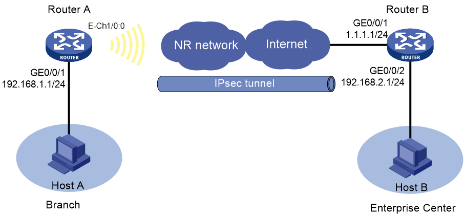
As shown in Figure 3, Router A has a 5G modem module. The user accesses the 5G network through auto-dial DDR. Establish an IPsec tunnel between branch gateway Router A and headquarters gateway Router B to protect data flows between branch network 192.168.1.0/24 and headquarters network 192.168.2.0/24. Configure the routers to meet the following requirements:
· On Router A, configure traditional auto-dial DDR and establish a permanent 5G online connection.
· Specify the encapsulation mode as the tunnel mode, the security protocol as ESP, the encryption algorithm as DES-CBC, and the authentication algorithm as SHA1. Establish IPsec SAs through IKE negotiations.
Analysis
On Router A, channelize Cellular 1/0 into Eth-channel interface Eth-channel 1/0:0. Enable Eth-channel 1/0:0 to obtain an IP address by using the modem-manufacturer's proprietary protocol. On Eth-channel 1/0:0, configure auto-dial DDR and establish a permanent 5G online connection.
Because the IP address of dialer interface Eth-channel 1/0:0 dynamically changes, you must use an IPsec policy template on Router B when you configure the IPsec tunnel. Specify the peer IP address as 0.0.0.0/0 and configure Router A to initiate the tunnel establishment request.
For Router B to have a private network route to each branch gateway, enable IPsec reverse route inject (RRI) on Router B. Then, Router B automatically creates static routes upon IPsec SA creation.
Restrictions and guidelines
When a common 5G SIM card is used for network access, the router can access the 5G network after you use an APN automatically assigned by the service provider in the 5G modem profile. When a 5G IoT or VPDN SIM card is used, you must use the APN provided by the service provider in the 5G modem profile. You must also configure the authentication method for 5G network access based on the username and password provided by the service provider.
Procedures
Configuring Router A
1. Assign an IP address to the interface. (Details not shown.)
2. Configure 5G modem dialup:
# Configure a dialup rule for dialer group 1.
<RouterA> system-view
[RouterA] dialer-group 1 rule ip permit
# Configure an APN profile named dynamic1, and use an APN automatically assigned by the service provider.
[RouterA] apn-profile dynamic1
[RouterA-apn-profile-vpdn1] apn dynamic
[RouterA-apn-profile-vpdn1] quit
# Channelize Cellular 1/0 into an Eth-channel interface.
[RouterA] controller cellular 1/0
[RouterA-Cellular1/0] eth-channel 0
[RouterA-Cellular1/0] quit
# Enable Eth-channel 1/0:0 to obtain an IP address by using the modem-manufacturer's proprietary protocol.
[RouterA] interface eth-channel 1/0:0
[RouterA-Eth-channel1/0:0] ip address cellular-alloc
# Apply APN profile dynamic1 to Eth-channel 1/0:0.
[RouterA-Eth-channel1/0:0] apn-profile apply dynamic1
# Enable traditional DDR on Eth-channel 1/0:0 and associate Eth-channel 1/0:0 with dialer group 1.
[RouterA-Eth-channel1/0:0] dialer circular enable
[RouterA-Eth-channel1/0:0] dialer-group 1
# Set the link idle-timeout timer to 0 seconds, wait-carrier timer to 30 seconds, and auto-dial timer to 5 seconds.
[RouterA-Eth-channel1/0:0] dialer timer idle 0
[RouterA-Eth-channel1/0:0] dialer timer wait-carrier 30
[RouterA-Eth-channel1/0:0] dialer timer autodial 5
# Set the dial string for placing calls. Typically, set the dial string for placing calls to *99# for China Mobile or China Unicom and #777 for China Telecom in China mainland.
[RouterA-Eth-channel1/0:0] dialer number *99# autodial
[RouterA-Eth-channel1/0:0] quit
# Configure the default route.
[RouterA] ip route-static 0.0.0.0 0 eth-channel 1/0:0
3. Configure the IPsec policy:
# Configure IPv4 advanced ACL 3001 to identify traffic from subnet 192.168.1.0/24 to subnet 192.168.2.0/24.
[RouterA] acl advanced 3001
[RouterA-acl-ipv4-adv-3001] rule 0 permit ip source 192.168.1.0 0.0.0.255 destination 192.168.2.0 0.0.0.255
[RouterA-acl-ipv4-adv-3001] quit
# Create an IPsec transform set named tran1, and use tunnel as the packet encapsulation mode, SHA1 as the authentication algorithm, and DES-CBC as the encryption algorithm.
[RouterA] ipsec transform-set tran1
[RouterA-ipsec-transform-set-tran1] encapsulation-mode tunnel
[RouterA-ipsec-transform-set-tran1] protocol esp
[RouterA-ipsec-transform-set-tran1] esp authentication-algorithm sha1
[RouterA-ipsec-transform-set-tran1] esp encryption-algorithm des-cbc
[RouterA-ipsec-transform-set-tran1] quit
# Create an IKE proposal named 1, and use 3DES as the encryption algorithm, HMAC-SHA1 as the authentication algorithm, and pre-share as the authentication method.
[RouterA] ike proposal 1
[RouterA-ike-proposal-1] encryption-algorithm 3des-cbc
[RouterA-ike-proposal-1] authentication-algorithm sha
[RouterA-ike-proposal-1] authentication-method pre-share
[RouterA-ike-proposal-1] quit
# Create an IKE keychain named key1 and use 123456 in plain text as the pre-shared key to be used with the remote peer at 1.1.1.1.
[RouterA] ike keychain key1
[RouterA-ike-keychain-key1] pre-shared-key address 1.1.1.1 255.255.255.0 key simple 123456
[RouterA-ike-keychain-key1] quit
# Create an IKE profile named ike1. Specify IKE keychain key1 for the IKE profile, configure a peer ID with the identity type of IP address and the value of 1.1.1.1, and configure DPD to be triggered every 5 seconds on demand.
[RouterA] ike profile ike1
[RouterA-ike-profile-ike1] keychain key1
[RouterA-ike-profile-ike1] match remote identity address 1.1.1.1 255.255.255.0
[RouterA-ike-profile-ike1] dpd interval 5 on-demand
[RouterA-ike-profile-ike1] quit
# Create an IKE-based IPsec policy named policy1. Specify IPsec transform set tran1, IKE profile ike1, and IPv4 advanced ACL 3001 for the policy, and remote IP address 1.1.1.1 for the IPsec tunnel.
[RouterA] ipsec policy policy1 10 isakmp
[RouterA-ipsec-policy-isakmp-policy1-10] transform-set tran1
[RouterA-ipsec-policy-isakmp-policy1-10] ike-profile ike1
[RouterA-ipsec-policy-isakmp-policy1-10] security acl 3001
[RouterA-ipsec-policy-isakmp-policy1-10] remote-address 1.1.1.1
[RouterA-ipsec-policy-isakmp-policy1-10] quit
# Apply IPsec policy policy1 to Eth-channel 1/0:0.
[RouterA] interface eth-channel 1/0:0
[RouterA-Eth-channel1/0:0] ipsec apply policy policy1
[RouterA-Eth-channel1/0:0] quit
Configuring Router B
1. Assign IP addresses to interfaces. (Details not shown.) By default, Router B has a default route to the next hop belonging to the public network.
2. Configure the IPsec policy:
# Configure IPv4 advanced ACL 3003 to identify traffic from subnet 192.168.2.0/24 to subnet 192.168.1.0/24.
<RouterB> system-view
[RouterB] acl advanced 3003
[RouterB-acl-ipv4-adv-3003] rule 0 permit ip source 192.168.2.0 0.0.0.255 destination 192.168.1.0 0.0.0.255
[RouterB-acl-ipv4-adv-3003] quit
# Create an IPsec transform set named tran1, and use SHA1 as the authentication algorithm, and DES-CBC as the encryption algorithm.
[RouterB] ipsec transform-set tran1
[RouterB-ipsec-transform-set-tran1] encapsulation-mode tunnel
[RouterB-ipsec-transform-set-tran1] protocol esp
[RouterB-ipsec-transform-set-tran1] esp authentication-algorithm sha1
[RouterB-ipsec-transform-set-tran1] esp encryption-algorithm des-cbc
[RouterB-ipsec-transform-set-tran1] quit
# Create an IKE proposal named 1, and use 3DES as the encryption algorithm, HMAC-SHA1 as the authentication algorithm, and pre-share as the authentication method.
[RouterB] ike proposal 1
[RouterB-ike-proposal-1] encryption-algorithm 3des-cbc
[RouterB-ike-proposal-1] authentication-algorithm sha
[RouterB-ike-proposal-1] authentication-method pre-share
[RouterB-ike-proposal-1] quit
# Create an IKE keychain named key1 and use 123456 in plain text as the pre-shared key to be used with the remote peer.
[RouterB] ike keychain key1
[RouterB-ike-keychain-key1] pre-shared-key address 0.0.0.0 0.0.0.0 key simple 123456
[RouterB-ike-keychain-key1] quit
# Create an IKE profile named ike1. Specify IKE keychain key1 for the IKE profile, and configure a peer ID with the identity type of IP address and the value of 0.0.0.0.
[RouterB] ike profile ike1
[RouterB-ike-profile-ike1] keychain key1
[RouterB-ike-profile-ike1] match remote identity address 0.0.0.0 0.0.0.0
[RouterB-ike-profile-ike1] quit
# Create an IPsec policy template named temp1. Specify IPsec transform set tran1, IKE profile ike1, and IPv4 advanced ACL 3003 for the IPsec policy template.
[RouterB] ipsec policy-template temp1 1
[RouterB-ipsec-policy-template-temp1-1] transform-set tran1
[RouterB-ipsec-policy-template-temp1-1] ike-profile ike1
[RouterB-ipsec-policy-template-temp1-1] security acl 3003
# Enable IPsec RRI.
[RouterB-ipsec-policy-template-temp1-1] reverse-route dynamic
[RouterB-ipsec-policy-template-temp1-1] quit
# Create an IKE-based IPsec policy entry by using IPsec policy template temp1. Specify the policy name as policy1 and set the sequence number to 1.
[RouterB] ipsec policy policy1 10 isakmp template temp1
# Apply IPsec policy policy1 to GigabitEthernet 0/0/1.
[RouterB] interface gigabitethernet 0/0/1
[RouterB-GigabitEthernet0/0/1] ipsec apply policy policy1
[RouterB-GigabitEthernet0/0/1] quit
Verifying the configuration
# Initiate a connection from branch subnet 192.168.1.0/24 to headquarters subnet 192.168.2.0/24 to trigger IKE negotiation. After IPsec SAs are successfully negotiated by IKE, traffic between the two subnets is IPsec-protected.
# Verify that Router A and Router B can ping the private networks of each other. This example uses Router A.
<RouterA> ping -a 192.168.1.1 192.168.2.1
Ping 192.168.2.1 (192.168.2.1): 56 data bytes, press CTRL_C to break
56 bytes from 192.168.2.1: icmp_seq=0 ttl=254 time=7.343 ms
56 bytes from 192.168.2.1: icmp_seq=1 ttl=254 time=1.164 ms
56 bytes from 192.168.2.1: icmp_seq=2 ttl=254 time=1.080 ms
56 bytes from 192.168.2.1: icmp_seq=3 ttl=254 time=1.234 ms
56 bytes from 192.168.2.1: icmp_seq=4 ttl=254 time=1.391 ms
--- Ping statistics for 192.168.2.1 ---
5 packet(s) transmitted, 5 packet(s) received, 0.0% packet loss
round-trip min/avg/max/std-dev = 1.080/2.442/7.343/2.452 ms
# Verify that IPsec SAs are established on Router A.
<RouterA> display ipsec sa
-------------------------------
Interface: Eth-channel1/0:0
-------------------------------
-----------------------------
IPsec policy: policy
Sequence number: 10
Mode: ISAKMP
-----------------------------
Tunnel id: 0
Encapsulation mode: tunnel
Perfect Forward Secrecy:
Inside VPN:
Extended Sequence Numbers enable: N
Traffic Flow Confidentiality enable: N
Transmitting entity: Initiator
Path MTU: 1444
Tunnel:
local address/port: 2.2.2.1/500
remote address/port: 1.1.1.1/500
Flow:
sour addr: 192.168.1.0/255.255.255.0 port: 4500 protocol: ip
dest addr: 192.168.2.0/255.255.255.0 port: 4500 protocol: ip
...
Configuration files
· Router A:
#
interface gigabitethernet 0/0/1
ip address 192.168.1.1 255.255.255.0
#
dialer-group 1 rule ip permit
#
apn-profile dynamic1
apn dynamic
#
controller cellular 1/0
eth-channel 0
#
interface eth-channel 1/0:0
ip address cellular-alloc
apn-profile apply dynamic1
dialer circular enable
dialer-group 1
dialer timer idle 0
dialer timer wait-carrier 30
dialer timer autodial 5
dialer number *99# autodial
#
ip route-static 0.0.0.0 0.0.0.0 eth-channel 1/0:0
#
acl advanced 3001
rule 0 permit ip source 192.168.1.0 0.0.0.255 destination 192.168.2.0 0.0.0.255
#
ipsec transform-set tran1
encapsulation-mode tunnel
protocol esp
esp authentication-algorithm sha1
esp encryption-algorithm des-cbc
#
ike proposal 1
encryption-algorithm 3des-cbc
authentication-algorithm sha
authentication-method pre-share
#
ike keychain key1
pre-shared-key address 1.1.1.1 255.255.255.0 key cipher $c$3$6xffbOeJQiOn1UzvH2Vdd1H+2PenaF8c3g==
#
ike profile ike1
dpd interval 5 on-demand
keychain key1
match remote identity address 1.1.1.1 255.255.255.0
#
ipsec policy policy1 10 isakmp
transform-set tran1
ike-profile ike1
security acl 3001
remote-address 1.1.1.1
#
interface eth-channel 1/0:0
ipsec apply policy policy1
#
· Router B:
#
interface gigabitethernet 0/0/1
ip address 1.1.1.1 255.255.255.0
#
interface gigabitethernet 0/0/2
ip address 192.168.2.1 255.255.255.0
#
acl advanced 3003
rule 0 permit ip source 192.168.2.0 0.0.0.255 destination 192.168.1.0 0.0.0.255
#
ipsec transform-set tran1
encapsulation-mode tunnel
protocol esp
esp authentication-algorithm sha1
esp encryption-algorithm des-cbc
#
ike proposal 1
encryption-algorithm 3des-cbc
authentication-algorithm sha
authentication-method pre-share
#
ike keychain key1
pre-shared-key address 0.0.0.0 0.0.0.0 key cipher $c$3$6xffbOeJQiOn1UzvH2Vdd1H+2PenaF8c3g==
#
ike profile ike1
keychain key1
match remote identity address 0.0.0.0 0.0.0.0
#
ipsec policy-template temp1 1
transform-set tran1
ike-profile ike1
security acl 3003
#
reverse-route dynamic
#
ipsec policy policy1 10 isakmp template temp1
#
interface gigabitethernet 0/0/1
ipsec apply policy policy1
#
Example: Configuring 5G modem dialup and ADVPN tunnels
Software versions used
This configuration example was created and verified on R9141P16 of the MSR2630E-X1 device.
Network configuration
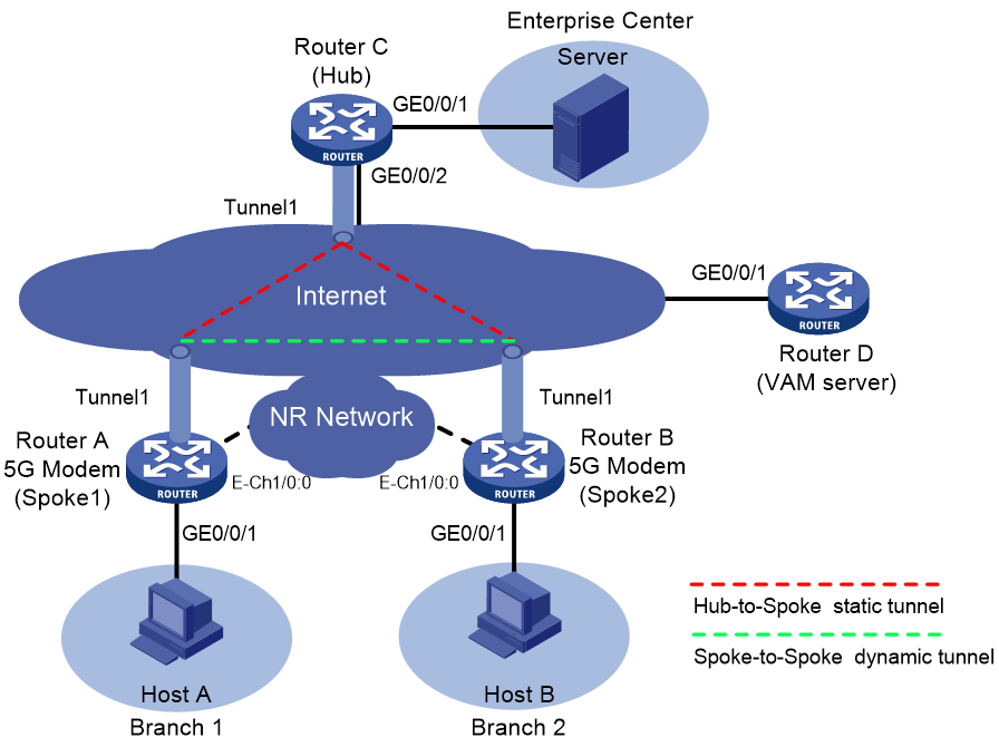
As shown in Figure 4, Router A has a 5G modem module. Users access the 5G network through auto-dial DDR. Establish ADVPN tunnels between branch gateways Router A and Router B and headquarters gateway Router C to realize full-mesh ADVPN between branch networks and between branch and headquarters networks. Configure the routers to meet the following requirements:
· On Router A, configure traditional auto-dial DDR and establish a permanent online connection.
· Router A and Router B act as spokes, and Router C acts as a hub. Establish a permanent ADVPN tunnel between the hub and each spoke.
· Configure ADVPN tunnels to be dynamically established based on data between spokes Router A and Router B.
|
Device |
Interface |
IP address |
Device |
Interface |
IP address |
|
Router A (Spoke1) |
GE0/0/1 |
192.168.1.1/24 |
Router C (Hub) |
GE0/0/1 |
192.168.3.1/24 |
|
|
Tunnel1 |
192.168.0.1/24 |
|
GE0/0/2 |
1.1.1.1/24 |
|
Router B (Spoke2) |
GE0/0/1 |
192.168.2.1/24 |
|
Tunnel1 |
192.168.0.3/24 |
|
|
Tunnel1 |
192.168.0.2/24 |
Router D (VAM server) |
GE0/0/1 |
1.1.1.2/24 |
Analysis
On Router A, channelize Cellular 1/0 into Eth-channel interface Eth-channel 1/0:0. Enable Eth-channel 1/0:0 to obtain an IP address by using the modem-manufacturer's proprietary protocol. On Eth-channel 1/0:0, configure auto-dial DDR and establish a permanent 5G online connection.
To ensure data privacy between branches and branches and headquarters, apply IPsec profiles to ADVPN tunnels for data encryption. Because the IP address of dialer interface Eth-channel 1/0:0 dynamically changes, specify the peer address as 0.0.0.0/0 when you apply IPsec profiles to ADVPN tunnels.
In this example, configure Router D (VAM server) not to authenticate Router A, Router B, and Router C (VAM clients). You can configure the VAM server to authenticate VAM clients as required.
Restrictions and guidelines
When a common 5G SIM card is used for network access, the router can access the 5G network after you use an APN automatically assigned by the service provider in the 5G modem profile. When a 5G IoT or VPDN SIM card is used, you must use the APN provided by the service provider in the 5G modem profile. You must also configure the authentication method for 5G network access based on the username and password provided by the service provider.
Procedures
Configuring Router A
1. Assign IP addresses to interfaces. (Details not shown.)
2. Configure 5G modem dialup:
# Configure a dialup rule for dialer group 1.
<RouterA> system-view
[RouterA] dialer-group 1 rule ip permit
# Configure an APN profile named dynamic1, and use an APN automatically assigned by the service provider.
[RouterA] apn-profile dynamic1
[RouterA-apn-profile-vpdn1] apn dynamic
[RouterA-apn-profile-vpdn1] quit
# Channelize Cellular 1/0 into an Eth-channel interface.
[RouterA] controller cellular 1/0
[RouterA-Cellular1/0] eth-channel 0
[RouterA-Cellular1/0] quit
# Enable Eth-channel1/0:0 to obtain an IP address automatically through the modem manufacturer's proprietary protocol.
[RouterA] interface eth-channel 1/0:0
[RouterA-Eth-channel1/0:0] ip address cellular-alloc
# Apply APN profile dynamic1 to Eth-channel 1/0:0.
[RouterA-Eth-channel1/0:0] apn-profile apply dynamic1
# Enable traditional DDR on Eth-channel 1/0:0 and associate Eth-channel 1/0:0 with dialer group 1.
[RouterA-Eth-channel1/0:0] dialer circular enable
[RouterA-Eth-channel1/0:0] dialer-group 1
# Set the link idle-timeout timer to 0 seconds, wait-carrier timer to 30 seconds, and auto-dial timer to 5 seconds.
[RouterA-Eth-channel1/0:0] dialer timer idle 0
[RouterA-Eth-channel1/0:0] dialer timer wait-carrier 30
[RouterA-Eth-channel1/0:0] dialer timer autodial 5
# Set the dial string for placing calls. Typically, set the dial string for placing calls to *99# for China Mobile or China Unicom and #777 for China Telecom in China mainland.
[RouterA-Eth-channel1/0:0] dialer number *99# autodial
# Configure an outbound dynamic NAT rule for Eth-channel 1/0:0.
[RouterA-Eth-channel1/0:0] nat outbound
[RouterA-Eth-channel1/0:0] quit
# Configure the default route.
[RouterA] ip route-static 0.0.0.0 0 eth-channel 1/0:0
3. Configure the VAM client:
# Create VAM client Spoke1 and specify ADVPN domain abc for the VAM client.
[RouterA] vam client name spoke1
[RouterA-vam-client-Spoke1] advpn-domain abc
# Configure the preshared key of the VAM client as 123456.
[RouterA-vam-client-Spoke1] pre-shared-key simple 123456
# Specify the IP address of the VAM server and enable the VAM client.
[RouterA-vam-client-Spoke1] server primary ip-address 1.1.1.2
[RouterA-vam-client-Spoke1] client enable
[RouterA-vam-client-Spoke1] quit
# Create an IKE keychain named key and use 123456 in plain text as the pre-shared key to be used with the remote peer.
[RouterA] ike keychain key
[RouterA-ike-keychain-key] pre-shared-key address 0.0.0.0 0.0.0.0 key simple 123456
[RouterA-ike-keychain-key] quit
# Create an IKE profile named ike and specify IKE keychain key for it.
[RouterA] ike profile ike
[RouterA-ike-profile-abc] keychain key
[RouterA-ike-profile-ike] quit
# Create an IPsec transform set named tran, and use transport as the packet encapsulation mode, SHA1 as the authentication algorithm, and DES-CBC as the encryption algorithm.
[RouterA] ipsec transform-set tran
[RouterA-ipsec-transform-set-tran] encapsulation-mode transport
[RouterA-ipsec-transform-set-tran] esp encryption-algorithm des-cbc
[RouterA-ipsec-transform-set-tran] esp authentication-algorithm sha1
[RouterA-ipsec-transform-set-tran] quit
# Create an IKE-based IPsec profile named profile1. Specify IPsec transform set tran and IKE profile ike for the IPsec profile.
[RouterA] ipsec profile profile1 isakmp
[RouterA-ipsec-profile-isakmp-profile1] transform-set tran
[RouterA-ipsec-profile-isakmp-profile1] ike-profile ike
[RouterA-ipsec-profile-isakmp-profile1] quit
# Configure OSPF to advertise the private networks.
[RouterA] ospf 1
[RouterA-ospf-1] area 0
[RouterA-ospf-1-area-0.0.0.0] network 192.168.1.0 0.0.0.255
[RouterA-ospf-1-area-0.0.0.0] network 192.168.0.0 0.0.0.255
[RouterA-ospf-1-area-0.0.0.0] quit
[RouterA-ospf-1] quit
# Configure a GRE-mode IPv4 ADVPN tunnel interface named Tunnel1. Set its DR priority to 0 to prevent Router A from participating in DR/BDR election.
[RouterA] interface tunnel1 mode advpn gre
[RouterA-Tunnel1] ip address 192.168.0.1 255.255.255.0
[RouterA-Tunnel1] vam client spoke1
[RouterA-Tunnel1] ospf network-type broadcast
[RouterA-Tunnel1] ospf dr-priority 0
[RouterA-Tunnel1] source eth-channel 1/0:0
[RouterA-Tunnel1] tunnel protection ipsec profile ipsec
[RouterA-Tunnel1] quit
Configuring Router B
1. Assign IP addresses to interfaces. (Details not shown.)
2. Configure 5G modem dialup.
# Configure a dialup rule for dialer group 1.
<RouterB> system-view
[RouterB] dialer-group 1 rule ip permit
# Configure an APN profile named dynamic1, and use an APN automatically assigned by the service provider.
[RouterB] apn-profile dynamic1
[RouterB-apn-profile-vpdn1] apn dynamic
[RouterB-apn-profile-vpdn1] quit
# Channelize Cellular 1/0 into an Eth-channel interface.
[RouterB] controller cellular 1/0
[RouterB-Cellular1/0] eth-channel 0
[RouterB-Cellular1/0] quit
# Enable Eth-channel1/0:0 to obtain an IP address automatically through the modem manufacturer's proprietary protocol.
[RouterB] interface eth-channel 1/0:0
[RouterB-Eth-channel1/0:0] ip address cellular-alloc
# Apply APN profile dynamic1 to Eth-channel 1/0:0.
[RouterB-Eth-channel1/0:0] apn-profile apply dynamic1
# Enable traditional DDR on Eth-channel 1/0:0 and associate Eth-channel 1/0:0 with dialer group 1.
[RouterB-Eth-channel1/0:0] dialer circular enable
[RouterB-Eth-channel1/0:0] dialer-group 1
# Set the link idle-timeout timer to 0 seconds, wait-carrier timer to 30 seconds, and auto-dial timer to 5 seconds.
[RouterB-Eth-channel1/0:0] dialer timer idle 0
[RouterB-Eth-channel1/0:0] dialer timer wait-carrier 30
[RouterB-Eth-channel1/0:0] dialer timer autodial 5
# Set the dial string for placing calls. Typically, set the dial string for placing calls to *99# for China Mobile or China Unicom and #777 for China Telecom in China mainland.
[RouterB-Eth-channel1/0:0] dialer number *99# autodial
# Configure an outbound dynamic NAT rule for Eth-channel 1/0:0.
[RouterB-Eth-channel1/0:0] nat outbound
[RouterB-Eth-channel1/0:0] quit
# Configure the default route.
[RouterB] ip route-static 0.0.0.0 0 eth-channel 1/0:0
3. Configure the VAM client:
# Create VAM client Spoke2 and specify ADVPN domain abc for the VAM client.
[RouterB] vam client name spoke2
[RouterB-vam-client-Spoke2] advpn-domain abc
# Configure the preshared key of the VAM client as 123456.
[RouterB-vam-client-Spoke2] pre-shared-key simple 123456
# Specify the IP address of the VAM server and enable the VAM client.
[RouterB-vam-client-Spoke2] server primary ip-address 1.1.1.2
[RouterB-vam-client-Spoke2] client enable
[RouterB-vam-client-Spoke2] quit
# Create an IKE keychain named key and use 123456 in plain text as the pre-shared key to be used with the remote peer.
[RouterB] ike keychain key
[RouterB-ike-keychain-key] pre-shared-key address 0.0.0.0 0.0.0.0 key simple 123456
[RouterB-ike-keychain-key] quit
# Create an IKE profile named ike and specify IKE keychain key for it.
[RouterB] ike profile ike
[RouterB-ike-profile-ike] keychain key
[RouterB-ike-profile-ike] quit
# Create an IPsec transform set named tran, and use transport as the packet encapsulation mode, SHA1 as the authentication algorithm, and DES-CBC as the encryption algorithm.
[RouterB] ipsec transform-set tran
[RouterB-ipsec-transform-set-tran] encapsulation-mode transport
[RouterB-ipsec-transform-set-tran] esp encryption-algorithm des-cbc
[RouterB-ipsec-transform-set-tran] esp authentication-algorithm sha1
[RouterB-ipsec-transform-set-tran] quit
# Create an IKE-based IPsec profile named profile1. Specify IPsec transform set tran and IKE profile ike for the IPsec profile.
[RouterB] ipsec profile profile1 isakmp
[RouterB-ipsec-profile-isakmp-profile1] transform-set tran
[RouterB-ipsec-profile-isakmp-profile1] ike-profile ike
[RouterB-ipsec-profile-isakmp-profile1] quit
# Configure OSPF to advertise the private networks.
[RouterB] ospf 1
[RouterB-ospf-1] area 0
[RouterB-ospf-1-area-0.0.0.0] network 192.168.2.0 0.0.0.255
[RouterB-ospf-1-area-0.0.0.0] network 192.168.0.0 0.0.0.255
[RouterB-ospf-1-area-0.0.0.0] quit
[RouterB-ospf-1] quit
# Configure a GRE-mode IPv4 ADVPN tunnel interface named Tunnel1. Set its DR priority to 0 to prevent Router B from participating in DR/BDR election.
[RouterB] interface tunnel1 mode advpn gre
[RouterB-Tunnel1] ip address 192.168.0.2 255.255.255.0
[RouterB-Tunnel1] vam client spoke2
[RouterB-Tunnel1] ospf network-type broadcast
[RouterB-Tunnel1] ospf dr-priority 0
[RouterB-Tunnel1] source eth-channel 1/0:0
[RouterB-Tunnel1] tunnel protection ipsec profile ipsec
[RouterB-Tunnel1] quit
Configuring Router C
1. Assign IP addresses to interfaces. (Details not shown.) By default, Router C has a default route to the next hop belonging to the public network.
2. Configure the VAM client:
# Configure an outbound dynamic NAT rule for GigabitEthernet 0/0/2.
<RouterC> system-view
[RouterC] interface gigabitethernet 0/0/2
[RouterC-GigabitEthernet0/0/2] nat outbound
[RouterC-GigabitEthernet0/0/2] quit
# Create VAM client Hub and specify ADVPN domain abc for the VAM client.
[RouterC] vam client name Hub
[RouterC-vam-client-Hub] advpn-domain abc
# Configure the preshared key of the VAM client as 123456.
[RouterC-vam-client-Hub] pre-shared-key simple 123456
# Specify the IP address of the VAM server and enable the VAM client.
[RouterC-vam-client-Hub] server primary ip-address 1.1.1.2
[RouterC-vam-client-Hub] client enable
[RouterC-vam-client-Hub] quit
# Create an IKE keychain named key and use 123456 in plain text as the pre-shared key to be used with the remote peer.
[RouterC] ike keychain key
[RouterC-ike-keychain-key] pre-shared-key address 0.0.0.0 0.0.0.0 key simple 123456
[RouterC-ike-keychain-key] quit
# Create an IKE profile named ike and specify IKE keychain key for it.
[RouterC] ike profile ike
[RouterC-ike-profile-ike] keychain key
[RouterC-ike-profile-ike] quit
# Create an IPsec transform set named tran, and use transport as the packet encapsulation mode, SHA1 as the authentication algorithm, and DES-CBC as the encryption algorithm.
[RouterC] ipsec transform-set tran
[RouterC-ipsec-transform-set-tran] encapsulation-mode transport
[RouterC-ipsec-transform-set-tran] esp encryption-algorithm des-cbc
[RouterC-ipsec-transform-set-tran] esp authentication-algorithm sha1
[RouterC-ipsec-transform-set-tran] quit
# Create an IKE-based IPsec profile named profile1. Specify IPsec transform set tran and IKE profile ike for the IPsec profile.
[RouterC] ipsec profile profile1 isakmp
[RouterC-ipsec-profile-isakmp-profile1] transform-set tran
[RouterC-ipsec-profile-isakmp-profile1] ike-profile ike
[RouterC-ipsec-profile-isakmp-profile1] quit
# Configure OSPF to advertise the private networks.
[RouterC] ospf 1
[RouterC-ospf-1] area 0
[RouterC-ospf-1-area-0.0.0.0] network 192.168.0.0 0.0.0.255
[RouterC-ospf-1-area-0.0.0.0] network 192.168.3.0 0.0.0.255
[RouterC-ospf-1-area-0.0.0.0] quit
[RouterC-ospf-1] quit
# Configure a GRE-mode IPv4 ADVPN tunnel interface named Tunnel1.
[RouterC] interface tunnel1 mode advpn gre
[RouterC-Tunnel1] ip address 192.168.0.3 255.255.255.0
[RouterC-Tunnel1] vam client Hub
[RouterC-Tunnel1] ospf network-type broadcast
[RouterC-Tunnel1] source gigabitethernet 0/0/2
[RouterC-Tunnel1] tunnel protection ipsec profile ipsec
[RouterC-Tunnel1] quit
Configuring Router D
1. Assign an IP address to the interface. (Details not shown.) By default, Router D has a default route to the next hop belonging to the public network.
2. Configure the VAM server:
# Create ADVPN domain abc.
<RouterD> system-view
[RouterD] vam server advpn-domain abc id 1
# Create hub group 0.
[RouterD-vam-server-domain-abc] hub-group 0
# Specify the private IPv4 address as 192.168.0.3 and the public address as 1.1.1.1 (after NAT).
[RouterD-vam-server-domain-abc-hub-group-0] hub private-address 192.168.0.3 public-address 1.1.1.1
# Specify the IPv4 private network address range for spokes in the hub group.
[RouterD-vam-server-domain-abc-hub-group-0] spoke private-address network 192.168.0.0 255.255.255.0
[RouterD-vam-server-domain-abc-hub-group-0] quit
# Configure the preshared key of the VAM server as 123456 and configure the VAM server not to authenticate the VAM clients.
[RouterD-vam-server-domain-abc] pre-shared-key simple 123456
[RouterD-vam-server-domain-abc] authentication-method none
# Enable the VAM server for the ADVPN domain.
[RouterD-vam-server-domain-abc] server enable
[RouterD-vam-server-domain-abc] quit
Verifying the configuration
# Verify that ADVPN tunnels are established between Router A, Router B, and Router C, and their private networks can communicate with each other.
# Display IPv4 address mapping information for all VAM clients registered with the VAM server.
[RouterD] display vam server address-map
Total private address mappings: 3
Group Private address Public address Type NAT Holding time
0 192.168.0.1 1.1.1.2 Spoke Yes 0H 4M 35S
0 192.168.0.2 1.1.1.3 Spoke Yes 0H 4M 17S
0 192.168.0.3 1.1.1.1 Hub No 0H 2M 42S
The output shows that the hub, Spoke1, and Spoke2 have all registered their address mapping information with the VAM server.
# Verify that Spoke1 can ping private address 192.168.2.1 of Spoke2.
<RouterA> ping 192.168.2.1
Ping 192.168.2.1 (192.168.2.1): 56 data bytes, press CTRL_C to break
56 bytes from 192.168.2.1: icmp_seq=0 ttl=255 time=2.000 ms
56 bytes from 192.168.2.1: icmp_seq=1 ttl=255 time=60.000 ms
56 bytes from 192.168.2.1: icmp_seq=2 ttl=255 time=7.000 ms
56 bytes from 192.168.2.1: icmp_seq=3 ttl=255 time=1.000 ms
56 bytes from 192.168.2.1: icmp_seq=4 ttl=255 time=1.000 ms
--- Ping statistics for 192.168.2.1 ---
5 packet(s) transmitted, 5 packet(s) received, 0.0% packet loss
round-trip min/avg/max/std-dev = 1.080/2.442/7.343/2.452 ms
# Display IPv4 ADVPN tunnel information on Spoke1.
[RouterA] display advpn session
Interface : Tunnel1
Number of sessions: 2
Private address Public address Port Type State Holding time
192.168.0.2 1.1.1.3 -- S-S Establishing 0H 0M 22S
192.168.0.3 1.1.1.1 -- S-H Success 0H 1M 25S
# Display IPv4 ADVPN tunnel information on the hub.
[RouterC] display advpn session
Interface : Tunnel1
Number of sessions: 2
Private address Public address Port Type State Holding time
192.168.0.1 1.1.1.2 -- H-S Success 0H 2M 40S
192.168.0.2 1.1.1.3 -- H-S Success 0H 1M 53S
Configuration files
· Router A:
#
interface gigabitethernet 0/0/1
ip address 192.168.1.1 255.255.255.0
#
dialer-group 1 rule ip permit
#
apn-profile dynamic1
apn dynamic
#
controller cellular 1/0
eth-channel 0
#
interface eth-channel 1/0:0
ip address cellular-alloc
apn-profile apply dynamic1
dialer circular enable
dialer-group 1
dialer timer idle 0
dialer timer wait-carrier 30
dialer timer autodial 5
dialer number *99# autodial
nat outbound
#
ip route-static 0.0.0.0 0 eth-channel 1/0:0
vam client name spoke1
advpn-domain abc
pre-shared-key cipher $c$3$k4hxzHYdkYZ8QUIr6+XsNTxsG/lGk6SGeQ==
server primary ip-address 1.1.1.2
client enable
#
ike keychain key
pre-shared-key address 0.0.0.0 0.0.0.0 key cipher $c$3$i/ODxQdpM7b0kmqHCMj+VpV6G+x/IBDycg==
#
ike profile ike
keychain key
#
ipsec transform-set tran
encapsulation-mode transport
esp encryption-algorithm des-cbc
esp authentication-algorithm sha1
#
ipsec profile profile1 isakmp
transform-set tran
ike-profile ike
#
ospf 1
area 0
network 192.168.1.0 0.0.0.255
network 192.168.0.0 0.0.0.255
#
interface tunnel1 mode advpn gre
ip address 192.168.0.1 255.255.255.0
vam client spoke1
ospf network-type broadcast
ospf dr-priority 0
source eth-channel 1/0:0
tunnel protection ipsec profile ipsec
#
· Router B:
#
interface gigabitethernet 0/0/1
ip address 192.168.2.1 255.255.255.0
#
dialer-group 1 rule ip permit
#
apn-profile dynamic1
apn dynamic
#
controller cellular 1/0
eth-channel 0
#
interface eth-channel 1/0:0
ip address cellular-alloc
apn-profile apply dynamic1
dialer circular enable
dialer-group 1
dialer timer idle 0
dialer timer wait-carrier 30
dialer timer autodial 5
dialer number *99# autodial
nat outbound
#
ip route-static 0.0.0.0 0 eth-channel 1/0:0
vam client name spoke2
advpn-domain abc
pre-shared-key cipher $c$3$k4hxzHYdkYZ8QUIr6+XsNTxsG/lGk6SGeQ==
server primary ip-address 1.1.1.2
client enable
#
ike keychain key
pre-shared-key address 0.0.0.0 0.0.0.0 key cipher $c$3$i/ODxQdpM7b0kmqHCMj+VpV6G+x/IBDycg==
#
ike profile ike
keychain key
#
ipsec transform-set tran
encapsulation-mode transport
esp encryption-algorithm des-cbc
esp authentication-algorithm sha1
#
ipsec profile profile1 isakmp
transform-set tran
ike-profile ike
#
ospf 1
area 0
network 192.168.2.0 0.0.0.255
network 192.168.0.0 0.0.0.255
#
interface tunnel1 mode advpn gre
ip address 192.168.0.2 255.255.255.0
vam client spoke2
ospf network-type broadcast
ospf dr-priority 0
source eth-channel 1/0:0
tunnel protection ipsec profile ipsec
#
· Router C:
#
interface gigabitethernet 0/0/1
ip address 192.168.3.1 255.255.255.0
#
interface gigabitethernet 0/0/2
ip address 1.1.1.1 255.255.255.0
nat outbound
#
vam client name Hub
advpn-domain abc
pre-shared-key cipher $c$3$k4hxzHYdkYZ8QUIr6+XsNTxsG/lGk6SGeQ==
server primary ip-address 1.1.1.2
client enable
#
ike keychain key
pre-shared-key address 0.0.0.0 0.0.0.0 key cipher $c$3$i/ODxQdpM7b0kmqHCMj+VpV6G+x/IBDycg==
#
ike profile ike
keychain key
#
ipsec transform-set tran
encapsulation-mode transport
esp encryption-algorithm des-cbc
esp authentication-algorithm sha1
#
ipsec profile profile1 isakmp
transform-set tran
ike-profile ike
#
ospf 1
area 0
network 192.168.0.0 0.0.0.255
network 192.168.3.0 0.0.0.255
#
interface tunnel1 mode advpn gre
ip address 192.168.0.3 255.255.255.0
vam client Hub
ospf network-type broadcast
source gigabitethernet 0/0/2
tunnel protection ipsec profile ipsec
#
· Router D:
#
interface gigabitethernet 0/0/1
ip address 1.1.1.2 255.255.255.0
#
vam server advpn-domain abc id 1
hub-group 0
hub private-address 192.168.0.3 public-address 1.1.1.1
spoke private-address network 192.168.0.0 255.255.255.0
#
pre-shared-key cipher $c$3$qb30FA4sK0lRsl3UgtHXhVZwwJtz4YdPrg==
authentication-method none
server enable
#
Example: Configuring 5G modem dialup and a VPDN tunnel
Software versions used
This configuration example was created and verified on R9141P16 of the MSR2630E-X1 device.
Network configuration
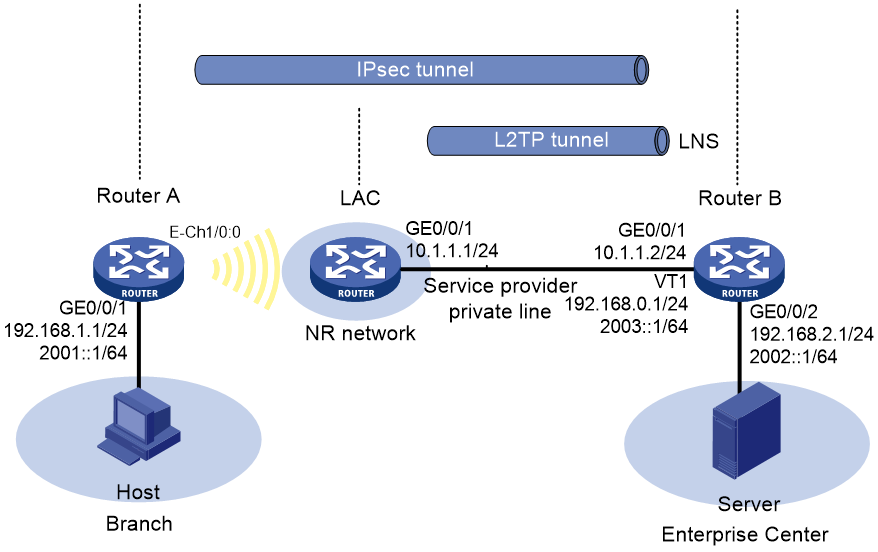
As shown in Figure 5, Router A has a 5G modem module. The user accesses the VPDN network of the service provider through auto-dial DDR. Establish an IPsec tunnel between branch gateway Router A and headquarters gateway Router B, and establish an L2TP tunnel between the service provider device LAC and Router B. Configure the devices to meet the following requirements:
· Configure traditional DDR on Router A to allow it to access the 5G network through both IPv4 and IPv6 and establish a permanent 5G online connection.
· Establish a NAS-initiated L2TP tunnel between the LAC and Router B. Traffic between the branch and the headquarters gateways goes through the service provider private line, which is isolated from the public network.
· Configure an IKE-based IPsec tunnel between Router A and Router B to encrypt traffic between the branch and headquarters gateways.
Analysis
On Router A, channelize Cellular 1/0 into Eth-channel interface Eth-channel 1/0:0. Enable Eth-channel 1/0:0 to obtain an IP address by using the modem-manufacturer's proprietary protocol. On Eth-channel 1/0:0, configure auto-dial DDR to access the service provider VPDN network and configure a permanent online connection.
Establish a NAS-initiated L2TP tunnel between the LAC and Router B. The LAC and Router B, serving as LNS devices, use local authentication.
Restrictions and guidelines
For the branch gateway to dial to the service provider VPDN network, use a VPDN SIM card for DDR dialup. When you configure DDR dialup, configure the 5G modem profile and dialup authentication based on the APN, authentication mode, username, and password of the service provider VPDN.
Procedures
Configuring Router A
1. Assign an IP address to the interface. (Details not shown.)
2. Configure 5G modem dialup:
# Configure a dialup rule for dialer group 1.
<RouterA> system-view
[RouterA] dialer-group 1 rule ip permit
[RouterA] dialer-group 1 rule ipv6 permit
# Configure an APN profile named vpdn1. Specify the IPv4 and IPv6 PDP data carrying protocols, APN vdpn, the CHAP or PAP authentication mode, username user1, and password password1. (Configure the APN, authentication mode, username, and password based on those provided by the service provider.)
[RouterA] apn-profile vpdn1
[RouterA-apn-profile-vpdn1] pdp-type ipv4v6
[RouterA-apn-profile-vpdn1] apn static vpdn
[RouterA-apn-profile-vpdn1] authentication-mode pap-chap user1 password simple password1
[RouterA-apn-profile-vpdn1] quit
# Channelize Cellular 1/0 into an Eth-channel interface.
[RouterA] controller cellular 1/0
[RouterA-Cellular1/0] eth-channel 0
[RouterA-Cellular1/0] quit
# Enable Eth-channel 1/0:0 to obtain an IPv4 address and an IPv6 address by using the modem-manufacturer's proprietary protocol.
[RouterA] interface eth-channel 1/0:0
[RouterA-Eth-channel1/0:0] ip address cellular-alloc
[RouterA-Eth-channel1/0:0] ipv6 address cellular-alloc
# Apply APN profile vpdn1 to Eth-channel 1/0:0.
[RouterA-Eth-channel1/0:0] apn-profile apply vpdn1
# Enable traditional DDR on Eth-channel 1/0:0 and associate Eth-channel 1/0:0 with dialer group 1.
[RouterA-Eth-channel1/0:0] dialer circular enable
[RouterA-Eth-channel1/0:0] dialer-group 1
# Set the link idle-timeout timer to 0 seconds, wait-carrier timer to 30 seconds, and auto-dial timer to 5 seconds.
[RouterA-Eth-channel1/0:0] dialer timer idle 0
[RouterA-Eth-channel1/0:0] dialer timer wait-carrier 30
[RouterA-Eth-channel1/0:0] dialer timer autodial 5
# Set the dial string for placing calls. Typically, set the dial string for placing calls to *99# for China Mobile or China Unicom and #777 for China Telecom in China mainland.
[RouterA-Eth-channel1/0:0] dialer number *99# autodial
[RouterA-Eth-channel1/0:0] quit
# Configure the default route.
[RouterA] ip route-static 0.0.0.0 0 eth-channel 1/0:0
[RouterA] ipv6 route-static 0::0 0 eth-channel 1/0:0
3. Configure the IPsec tunnel:
# Configure IPv4 advanced ACL 3000 to identify traffic from subnet 192.168.1.0/24 to subnet 192.168.2.0/24.
[RouterA] acl advanced 3000
[RouterA-acl-ipv4-adv-3000] rule 0 permit ip source 192.168.1.0 0.0.0.255 destination 192.168.2.0 0.0.0.255
[RouterA-acl-ipv4-adv-3000] quit
# Configure IPv6 advanced ACL 3500 to identify traffic from subnet 2001::/64 to subnet 2002::/64.
[RouterA] acl ipv6 advanced 3500
[RouterA-acl-ipv6-adv-3500] rule 0 permit ipv6 source 2001::0 64 destination 2002::0 64
[RouterA-acl-ipv6-adv-3500] quit
# Create an IPsec transform set named tran1, and use SHA1 as the authentication algorithm, and DES-CBC as the encryption algorithm.
[RouterA] ipsec transform-set tran1
[RouterA-ipsec-transform-set-tran1] encapsulation-mode tunnel
[RouterA-ipsec-transform-set-tran1] protocol esp
[RouterA-ipsec-transform-set-tran1] esp authentication-algorithm sha1
[RouterA-ipsec-transform-set-tran1] esp encryption-algorithm des-cbc
[RouterA-ipsec-transform-set-tran1] quit
# Create an IKE keychain named key1 and use 123456 in plain text as the pre-shared key to be used with the remote peer at 192.168.0.1 and 2003::1.
[RouterA] ike keychain key1
[RouterA-ike-keychain-key1] pre-shared-key address 192.168.0.1 24 key simple 123456
[RouterA-ike-keychain-key1] pre-shared-key address ipv6 2003::1 64 key simple 123456
[RouterA-ike-keychain-key1] quit
# Create an IKE profile named ike1 and specify IKE keychain key1 for it. Configure a peer ID with the identity type of IPv4 address and the value of 192.168.0.1. Configure a peer ID with the identity type of IPv6 address and the value as 2003::1.
[RouterA] ike profile ike1
[RouterA-ike-profile-ike1] keychain key1
[RouterA-ike-profile-ike1] match remote identity address 192.168.0.1 24
[RouterA-ike-profile-ike1] match remote identity address ipv6 2003::1 64
[RouterA-ike-profile-ike1] quit
# Create an IPv4 IKE-based IPsec policy named policy1. Specify IPsec transform set tran1, IKE profile ike1, and IPv4 advanced ACL 3000 for the policy, and remote IP address 192.168.0.1 for the IPsec tunnel.
[RouterA] ipsec policy policy1 10 isakmp
[RouterA-ipsec-policy-isakmp-policy1-10] transform-set tran1
[RouterA-ipsec-policy-isakmp-policy1-10] ike-profile ike1
[RouterA-ipsec-policy-isakmp-policy1-10] security acl 3000
[RouterA-ipsec-policy-isakmp-policy1-10] remote-address 192.168.0.1
[RouterA-ipsec-policy-isakmp-policy1-10] quit
# Create an IPv6 IKE-based IPsec policy named policy2. Specify IPsec transform set tran1, IKE profile ike1, and IPv6 advanced ACL 3500 for the policy, and remote IP address 2003::1 for the IPsec tunnel.
[RouterA] ipsec ipv6-policy policy2 20 isakmp
[RouterA-ipsec-policy-isakmp-policy2-20] transform-set tran1
[RouterA-ipsec-policy-isakmp-policy2-20] ike-profile ike1
[RouterA-ipsec-policy-isakmp-policy2-20] security acl ipv6 3500
[RouterA-ipsec-policy-isakmp-policy2-20] remote-address ipv6 2003::1
[RouterA-ipsec-policy-isakmp-policy2-20] quit
# Apply IPv4 IPsec policy policy1 and IPv6 IPsec policy policy2 to Eth-channel 1/0:0.
[RouterA] interface eth-channel 1/0:0
[RouterA-Eth-channel1/0:0] ipsec apply policy policy1
[RouterA-Eth-channel1/0:0] ipsec apply ipv6-policy policy2
[RouterA-Eth-channel1/0:0] quit
Configuring the LAC
1. Assign an IP address to the interface. (Details not shown.) The following configuration for the LAC is for your reference only. You do not need to configure the LAC during actual configuration.
2. Configure the LAC end on the L2TP tunnel:
# Create a local VPDN user with username user1 and password password1, and enable the PPP service.
<LAC> system-view
[LAC] local-user user1 class network
[LAC-luser-network-user1] password simple password1
[LAC-luser-network-user1] service-type ppp
[LAC-luser-network-user1] quit
# Configure ISP domain system to perform local AAA for VPDN users.
[LAC] domain system
[LAC-isp-system] authentication ppp local
[LAC-isp-system] quit
# Enable L2TP.
[LAC] l2tp enable
# Create L2TP group 1 in LAC mode. Specify the local tunnel name as LAC, the condition for the LAC to initiate tunneling requests as user1, and LNS IP address as 10.1.2.2.
[LAC] l2tp-group 1 mode lac
[LAC-l2tp1] tunnel name LAC
[LAC-l2tp1] user fullusername user1
[LAC-l2tp1] lns-ip 10.1.1.2
# Enable tunnel authentication, and set the tunnel authentication key to aabbcc.
[LAC-l2tp1] tunnel authentication
[LAC-l2tp1] tunnel password simple aabbcc
[LAC-l2tp1] quit
Configuring Router B
1. Assign an IP address to the interface. (Details not shown.) By default, Router B has a default route to the next hop belonging to the public network.
2. Configure the LNS end on the L2TP tunnel:
# Create a local VPDN user with username user1 and password password1, and enable the PPP service.
<RouterB> system-view
[RouterB] local-user user1 class network
[RouterB-luser-network-user1] password simple password1
[RouterB-luser-network-user1] service-type ppp
[RouterB-luser-network-user1] quit
# Configure ISP domain system to perform local AAA for VPDN users.
[RouterB] domain system
[RouterB-isp-system] authentication ppp local
# Specify the authorized IPv6 prefix 2013::/64.
[RouterB-isp-system] authorization-attribute ipv6-prefix 2003:: 64
[RouterB-isp-system] quit
# Enable L2TP, and create L2TP group 1 in LNS mode.
[RouterB] l2tp enable
[RouterB] l2tp-group 1 mode lns
# Configure the local tunnel name as LNS, and specify VT interface 1 for receiving calls from the peer (LAC) named LAC.
[RouterB-l2tp1] tunnel name LNS
[RouterB-l2tp1] allow l2tp virtual-template 1 remote LAC
# Enable tunnel authentication, and set the tunnel authentication key to aabbcc.
[RouterB-l2tp1] tunnel authentication
[RouterB-l2tp1] tunnel password simple aabbcc
[RouterB-l2tp1] quit
# Configure the PPP address pool.
[RouterB] ip pool aaa 192.168.0.10 192.168.0.20
[RouterB] ip pool aaa gateway 192.168.0.1
# Create Virtual-Template1 and specify IPv4 address 192.168.0.1/24 and IPv6 address 2003::1/64 for it. Enable the interface to advertise RA messages. Configure the interface to use CHAP and PAP for authenticating the peer and assign an IPv4 address from address pool aaa to Router A.
[RouterB] interface virtual-template 1
[RouterB-virtual-template1] ip address 192.168.0.1 255.255.255.0
[RouterB-virtual-template1] ipv6 address 2003::1 64
[RouterB-virtual-template1] undo ipv6 nd ra halt
[RouterB-virtual-template1] ppp authentication-mode chap pap domain system
[RouterB-virtual-template1] remote address pool aaa
[RouterB-virtual-template1] quit
3. Configure the IPsec tunnel:
# Create an IPsec transform set named tran1, and use ESP as the protocol, SHA1 as the authentication algorithm, and DES-CBC as the encryption algorithm.
[RouterB] ipsec transform-set tran1
[RouterB-ipsec-transform-set-tran1] encapsulation-mode tunnel
[RouterB-ipsec-transform-set-tran1] protocol esp
[RouterB-ipsec-transform-set-tran1] esp authentication-algorithm sha1
[RouterB-ipsec-transform-set-tran1] esp encryption-algorithm des-cbc
[RouterB-ipsec-transform-set-tran1] quit
# Create an IKE keychain named key1 and use 123456 in plain text as the pre-shared key to be used with the remote peer.
[RouterB] ike keychain key1
[RouterB-ike-keychain-key1] pre-shared-key address 0.0.0.0 0.0.0.0 key simple 123456
[RouterB-ike-keychain-key1] pre-shared-key address ipv6 0::0 0 key simple 123456
[RouterB-ike-keychain-key1] quit
# Create an IKE profile named ike1 and specify IKE keychain key1 for it. Configure a peer ID with the identity type of IPv4 address and the value of 0.0.0.0. Configure a peer ID with the identity type of IPv6 address and the value of 0::0.
[RouterB] ike profile ike1
[RouterB-ike-profile-ike1] keychain key1
[RouterB-ike-profile-ike1] match remote identity address 0.0.0.0 0.0.0.0
[RouterB-ike-profile-ike1] match remote identity address ipv6 0::0 0
[RouterB-ike-profile-ike1] quit
# Create an IPv4 IPsec policy template named temp1. Specify IPsec transform set tran1 and IKE profile ike1 for the IPsec policy template and enable IPsec RRI.
[RouterB] ipsec policy-template temp1 1
[RouterB-ipsec-policy-template-temp1-1] transform-set tran1
[RouterB-ipsec-policy-template-temp1-1] ike-profile ike1
[RouterB-ipsec-policy-template-temp1-1] reverse-route dynamic
[RouterB-ipsec-policy-template-temp1-1] quit
# Create an IPv6 IPsec policy template named temp2. Specify IPsec transform set tran1 and IKE profile ike1 for the IPsec policy template and enable IPsec RRI.
[RouterB] ipsec ipv6-policy-template temp2 2
[RouterB-ipsec-ipv6-policy-template-temp2-2] transform-set tran1
[RouterB-ipsec-ipv6-policy-template-temp2-2] ike-profile ike1
[RouterB-ipsec-ipv6-policy-template-temp2-2] reverse-route dynamic
[RouterB-ipsec-ipv6-policy-template-temp2-2] quit
# Create an IPv4 IKE-based IPsec policy entry by using IPsec policy template temp1. Specify the policy name as policy1 and set the sequence number to 10.
[RouterB] ipsec policy policy1 10 isakmp template temp1
# Create an IPv6 IKE-based IPsec policy entry by using IPsec policy template temp2. Specify the policy name as policy2 and set the sequence number to 20.
[RouterB] ipsec ipv6-policy policy2 20 isakmp template temp2
# Apply IPv4 IPsec policy policy1 and IPv6 IPsec policy policy2 to Virtual-Template 1.
[RouterB] interface virtual-template 1
[RouterB-Virtual-Template1] ipsec apply policy policy1
[RouterB-Virtual-Template1] ipsec apply ipv6-policy policy2
[RouterB-Virtual-Template1] quit
Verifying the configuration
# Verify that after Router A successfully accesses the network through DDR dialup, the LAC and Router B establish an L2TP tunnel and an L2TP session. The private networks of Router A and Router B can communicate with each other. Traffic forwarding between Router A and Router B also triggers IPsec tunnel establishment to encrypt the private network traffic between the routers.
# Display information about L2TP tunnels on Router B.
[RouterB] display l2tp tunnel
LocalTID RemoteTID State Sessions RemoteAddress RemotePort RemoteName
18986 558 Established 1 10.1.1.1 1701 LAC
[RouterB] display l2tp session
LocalSID RemoteSID LocalTID State
50693 61202 18986 Established
# Verify that IPsec SAs are established on Router A.
[RouterA] display ipsec sa
-------------------------------
Interface: Eth-channel1/0:0
-------------------------------
-----------------------------
IPsec policy: policy1
Sequence number: 10
Mode: ISAKMP
-----------------------------
Tunnel id: 0
Encapsulation mode: tunnel
Perfect Forward Secrecy:
Inside VPN:
Extended Sequence Numbers enable: N
Traffic Flow Confidentiality enable: N
Transmitting entity: Initiator
Path MTU: 1444
Tunnel:
local address/port: 192.168.0.10/500
remote address/port: 192.168.0.1/500
Flow:
sour addr: 192.168.1.0/255.255.255.0 port: 0 protocol: ip
dest addr: 192.168.2.0/255.255.255.0 port: 0 protocol: ip
[Inbound ESP SAs]
SPI: 367543574 (0x15e84516)
Connection ID: 4294967296
Transform set: ESP-ENCRYPT-DES-CBC ESP-AUTH-SHA1
SA duration (kilobytes/sec): 1843200/3600
SA remaining duration (kilobytes/sec): 1843199/3533
Max received sequence-number: 4
Anti-replay check enable: Y
Anti-replay window size: 64
UDP encapsulation used for NAT traversal: N
Status: Active
[Outbound ESP SAs]
SPI: 4212574134 (0xfb16c7b6)
Connection ID: 4294967297
Transform set: ESP-ENCRYPT-DES-CBC ESP-AUTH-SHA1
SA duration (kilobytes/sec): 1843200/3600
SA remaining duration (kilobytes/sec): 1843199/3533
Max sent sequence-number: 4
UDP encapsulation used for NAT traversal: N
Status: Active
-----------------------------
IPsec policy: policy2
Sequence number: 20
Alias: policy2-20
Mode: ISAKMP
-----------------------------
Tunnel id: 0
Encapsulation mode: tunnel
Perfect Forward Secrecy:
Inside VPN:
Extended Sequence Numbers enable: N
Traffic Flow Confidentiality enable: N
Transmitting entity: Initiator
Path MTU: 1424
Tunnel:
local address/port: 2003::F85B:7EE1:1410:74C9/500
remote address/port: 2003::1/500
Flow:
sour addr: 2001::/64 port: 0 protocol: ipv6
dest addr: 2002::/64 port: 0 protocol: ipv6
[Inbound ESP SAs]
SPI: 3314600301 (0xc590c96d)
Connection ID: 4294967296
Transform set: ESP-ENCRYPT-DES-CBC ESP-AUTH-SHA1
SA duration (kilobytes/sec): 1843200/3600
SA remaining duration (kilobytes/sec): 1843196/3462
Max received sequence-number: 29
Anti-replay check enable: Y
Anti-replay window size: 64
UDP encapsulation used for NAT traversal: N
Status: Active
[Outbound ESP SAs]
SPI: 3370073640 (0xc8df3e28)
Connection ID: 4294967297
Transform set: ESP-ENCRYPT-DES-CBC ESP-AUTH-SHA1
SA duration (kilobytes/sec): 1843200/3600
SA remaining duration (kilobytes/sec): 1843196/3462
Max sent sequence-number: 29
UDP encapsulation used for NAT traversal: N
Status: Active
Configuration files
· Router A:
#
interface gigabitethernet 0/0/1
ip address 192.168.1.1 255.255.255.0
ipv6 address 2001::1 64
#
dialer-group 1 rule ip permit
dialer-group 1 rule ipv6 permit
#
apn-profile vpdn1
pdp-type ipv4v6
apn static vpdn
authentication-mode pap-chap user1 password simple password1
#
controller cellular 1/0
eth-channel 0
#
interface eth-channel 1/0:0
ip address cellular-alloc
ipv6 address cellular-alloc
apn-profile apply vpdn1
dialer circular enable
dialer-group 1
dialer timer idle 0
dialer timer wait-carrier 30
dialer timer autodial 5
dialer number *99# autodial
ipsec apply policy policy1
ipsec apply ipv6-policy policy2
#
ip route-static 0.0.0.0 0 eth-channel 1/0:0
ipv6 route-static :: 0 eth-channel 1/0:0
#
acl advanced 3000
rule 0 permit ip source 192.168.1.0 0.0.0.255 destination 192.168.2.0 0.0.0.255
#
acl ipv6 advanced 3500
rule 0 permit ipv6 source 2001::/64 destination 2002::/64
#
ipsec transform-set tran1
encapsulation-mode tunnel
protocol esp
esp authentication-algorithm sha1
esp encryption-algorithm des-cbc
#
ike keychain key1
pre-shared-key address 192.168.0.1 255.255.255.0 key cipher $c$3$0kzuqazKcTGikVRekZ1E8R7jTOC2ZrJR2A==
pre-shared-key address ipv6 2003::1 64 key cipher $c$3$+93VGZhgfe4yG5D0d9VsLxWS6dlGVw2/Fw==
#
ike profile ike1
keychain key1
match remote identity address 192.168.0.1 255.255.255.0
match remote identity address ipv6 2003::1 64
#
ipsec policy policy1 10 isakmp
transform-set tran1
ike-profile ike1
security acl 3000
remote-address 192.168.0.1
#
ipsec ipv6-policy policy2 20 isakmp
transform-set tran1
security acl ipv6 3500
remote-address ipv6 2003::1
ike-profile ike1
#
· LAC:
#
interface gigabitethernet 0/0/1
ip address 10.1.1.1 255.255.255.0
#
local-user user1 class network
password simple password1
service-type ppp
#
domain system
authentication ppp local
#
l2tp enable
l2tp-group 1 mode lac
tunnel name LAC
user fullusername user1
lns-ip 10.1.1.2
tunnel authentication
tunnel password simple aabbcc
#
· Router B:
#
interface gigabitethernet 0/0/1
ip address 10.1.1.2 255.255.255.0
#
interface gigabitethernet 0/0/2
ip address 192.168.1.2 255.255.255.0
ipv6 address 2002::1 64
#
interface virtual-template 1
ip address 192.168.0.1 255.255.255.0
ipv6 address 2003::1 64
undo ipv6 nd ra halt
ppp authentication-mode chap pap domain system
remote address pool aaa
ipsec apply policy policy1
ipsec apply ipv6-policy policy2
#
local-user user1 class network
password simple password1
service-type ppp
#
domain system
authentication ppp local
authorization-attribute ipv6-prefix 2003:: 64
#
l2tp enable
l2tp-group 1 mode lns
tunnel name LNS
allow l2tp virtual-template 1 remote LAC
tunnel authentication
tunnel password simple aabbcc
#
ip pool aaa 192.168.0.10 192.168.0.20
ip pool aaa gateway 192.168.0.1
#
acl advanced 3000
rule 0 permit ip source 192.168.2.0 0.0.0.255 destination 192.168.1.0 0.0.0.255
#
acl ipv6 advanced 3500
rule 0 permit ipv6 source 2002::/64 destination 2001::/64
#
ipsec transform-set tran1
encapsulation-mode tunnel
protocol esp
esp authentication-algorithm sha1
esp encryption-algorithm des-cbc
#
ike keychain key1
pre-shared-key address 0.0.0.0 0.0.0.0 key cipher $c$3$vZXXcxKbhB/YCMg4oFr5IVJyrxwQTcB4Mg==
pre-shared-key address ipv6 0::0 0 key cipher $c$3$ua9potCkbZArSufmcQhY+LgLA+38vxmiXw==
#
ike profile ike1
keychain key1
match remote identity address 0.0.0.0 0.0.0.0
match remote identity address ipv6 :: 0
#
ipsec policy-template temp1 1
transform-set tran1
ike-profile ike1
security acl 3000
reverse-route dynamic
#
ipsec ipv6-policy-template temp2 2
transform-set tran1
security acl ipv6 3500
ike-profile ike1
reverse-route dynamic
#
ipsec policy policy1 10 isakmp template temp1
#
ipsec ipv6-policy policy2 20 isakmp template temp2
Example: Configuring 5G modem IPv6 dialup
Software versions used
This configuration example was created and verified on R9141P16 of the MSR2630E-X1 device.
Network configuration
As shown in Figure 6, Router A has a 5G modem module. The user accesses the IPv6 5G network through auto-dial DDR and a permanent online connection is established. Configure Router A to meet the following requirements:
· Configure traditional auto-dial DDR and establish a permanent 5G online connection.
· Enable traditional DDR on Eth-channel 1/0:0. Set the dial string for placing calls based on the service provider. Typically, set the dial string for placing calls to *99# for China Mobile or China Unicom and #777 for China Telecom in China mainland.
· Configure DDR to place calls for only IPv6 packets.

Analysis
On Router A, channelize Cellular 1/0 into Eth-channel interface Eth-channel 1/0:0. Enable Eth-channel 1/0:0 to obtain an IP address by using the modem-manufacturer's proprietary protocol. On Eth-channel 1/0:0, configure auto-dial DDR and establish a permanent 5G online connection.
Procedures
1. Assign an IP address to the interface. (Details not shown.)
2. Configure 5G modem dialup:
# Configure a dialup rule for dialer group 1.
<RouterA> system-view
[RouterA] dialer-group 1 rule ipv6 permit
# Configure an APN profile named dynamic1, and use an APN automatically assigned by the service provider.
[RouterA] apn-profile dynamic1
[RouterA-apn-profile-vpdn1] apn dynamic
[RouterA-apn-profile-vpdn1] quit
# Channelize Cellular 1/0 into an Eth-channel interface.
[RouterA] controller cellular 1/0
[RouterA-Cellular1/0] eth-channel 0
[RouterA-Cellular1/0] quit
# Enable Eth-channel1/0:0 to obtain an IP address automatically through the modem manufacturer's proprietary protocol.
[RouterA] interface eth-channel 1/0:0
[RouterA-Eth-channel1/0:0] ipv6 address cellular-alloc
# Apply APN profile dynamic1 to Eth-channel 1/0:0.
[RouterA-Eth-channel1/0:0] apn-profile apply dynamic1
# Enable traditional DDR on Eth-channel 1/0:0 and associate Eth-channel 1/0:0 with dialer group 1.
[RouterA-Eth-channel1/0:0] dialer circular enable
[RouterA-Eth-channel1/0:0] dialer-group 1
# Set the link idle-timeout timer to 0 seconds, wait-carrier timer to 30 seconds, and auto-dial timer to 5 seconds.
[RouterA-Eth-channel1/0:0] dialer timer idle 0
[RouterA-Eth-channel1/0:0] dialer timer wait-carrier 30
[RouterA-Eth-channel1/0:0] dialer timer autodial 5
# Set the dial string for placing calls. Typically, set the dial string for placing calls to *99# for China Mobile or China Unicom and #777 for China Telecom in China mainland.
[RouterA-Eth-channel1/0:0] dialer number *99# autodial
# On Eth-channel 1/0:0, configure an IPv6 source prefix mapping from 2001::/64 to 2002:0DF8:0001::/48.
[RouterA-Eth-channel1/0:0] nat66 prefix source 2001:: 64 2002:0df8:0001:: 48
[RouterA-Eth-channel1/0:0] quit
# Configure the default route.
[RouterA] ipv6 route-static :: 0 eth-channel 1/0:0
Verifying the configuration
# Verify that the configured default route takes effect and the user can access the network through the device.
[RouterA] display ipv6 routing-table
Destinations : 6 Routes : 6
Destination: ::/0 Protocol : Static
NextHop : ::1 Preference: 60
Interface : E-CH1/0:0 Cost : 0
Destination: 100::/128 Protocol : Direct
NextHop : ::1 Preference: 4
Interface : InLoop0 Cost : 0
Destination: 100::1/128 Protocol : Direct
NextHop : ::1 Preference: 4
Interface : InLoop0 Cost : 0
Destination: 100::7B/128 Protocol : Direct
NextHop : ::1 Preference: 4
Interface : InLoop0 Cost : 0
...
# Verify that the host can ping the external network, such as Baidu.
C:\Users\host1>ping www.baidu.com
Pinging www.baidu.com [112.80.248.76] with 32 bytes of data:
Reply from 112.80.248.76: Bytes=32 time=91ms TTL=122
Reply from 112.80.248.76: Bytes=32 time=92ms TTL=122
Reply from 112.80.248.76: Bytes=32 time=81ms TTL=122
Reply from 112.80.248.76: Bytes=32 time=88ms TTL=122
Ping statistics for 112.80.248.76:
Packets: Sent = 4, Received = 4, Lost = 0 (0% loss),
Approximate round trip time in milli-seconds:
Minimum = 81ms, Maximum = 92ms, Average = 88ms
Configuration files
#
interface gigabitethernet 0/0/1
ipv6 address 2001::1 64
#
dialer-group 1 rule ipv6 permit
#
apn-profile dynamic1
apn dynamic
#
controller cellular 1/0
eth-channel 0
#
dialer-group 1 rule ipv6 permit
controller cellular 1/0
eth-channel 0
#
interface eth-channel 1/0:0
ipv6 address cellular-alloc
apn-profile apply dynamic1
dialer circular enable
dialer-group 1
dialer timer idle 0
dialer timer wait-carrier 30
dialer timer autodial 5
dialer number *99# autodial
nat66 prefix source 2001:: 64 2002:0df8:0001:: 48
#
ipv6 route-static :: 0 eth-channel 1/0:0
#