- Table of Contents
-
- H3C MSR1000[2600][3600] Routers Configuration Examples All-in-One-R9141-6W100
- 00-Preface
- 01-Local 802.1X Authentication Configuration Examples
- 02-RADIUS-Based 802.1X Authentication Configuration Examples
- 03-AAA Configuration Examples
- 04-ACL Configuration Examples
- 05-MPLS over ADVPN Configuration Examples
- 06-ARP Attack Protection Configuration Examples
- 07-BFD Configuration Examples
- 08-Basic BGP Configuration Examples
- 09-BGP Route Attribute-Based Route Selection Configuration Examples
- 10-EAA Monitor Policy Configuration Examples
- 11-GRE with OSPF Configuration Examples
- 12-HoVPN Configuration Examples
- 13-IGMP Snooping Configuration Examples
- 14-IGMP Configuration Examples
- 15-IPsec Configuration Examples
- 16-IPsec Digital Certificate Authentication Configuration Examples
- 17-IPv6 IS-IS Configuration Examples
- 18-IPv6 over IPv4 GRE Tunnel Configuration Examples
- 19-IPv6 over IPv4 Manual Tunnel with OSPFv3 Configuration Examples
- 20-IS-IS Configuration Examples
- 21-Combined ISATAP Tunnel and 6to4 Tunnel Configuration Examples
- 22-L2TP over IPsec Configuration Examples
- 23-Multi-Instance L2TP Configuration Examples
- 24-L2TP Multidomain Access Configuration Examples
- 25-MPLS L3VPN Configuration Examples
- 26-MPLS OAM Configuration Examples
- 27-MPLS TE Configuration Examples
- 28-Basic MPLS Configuration Examples
- 29-NAT DNS Mapping Configuration Examples
- 30-NetStream Configuration Examples
- 31-NQA Configuration Examples
- 32-NTP Configuration Examples
- 33-OSPFv3 Configuration Examples
- 34-OSPF Configuration Examples
- 35-OSPF Multi-Process Configuration Examples
- 36-OSPF Multi-Instance Configuration Examples
- 37-Portal Configuration Examples
- 38-PPP Configuration Examples
- 39-RBAC Configuration Examples
- 40-RMON Configuration Examples
- 41-IPv4 NetStream Sampling Configuration Examples
- 42-SNMP Configuration Examples
- 43-SRv6 Configuration Examples
- 44-SSH Configuration Examples
- 45-Tcl Commands Configuration Examples
- 46-VLAN Configuration Examples
- 47-VRRP Configuration Examples
- 48-VXLAN over IPsec Configuration Examples
- 49-WLAN AC Configuration Examples
- 50-Small and Medium-Sized Store Configuration Examples
- 51-Cloudnet VPN Configuration Examples
- 52-Ethernet Link Aggregation Configuration Examples
- 53-Ethernet OAM Configuration Examples
- 54-Outbound Bidirectional NAT Configuration Examples
- 55-NAT Hairpin in C-S Mode Configuration Examples
- 56-Load Sharing NAT Server Configuration Examples
- 57-BIDIR-PIM Configuration Examples
- 58-Control Plane-Based QoS Policy Configuration Examples
- 59-Scheduling a Task Configuration Examples
- 60-Client-Initiated L2TP Tunnel Configuration Examples
- 61-LAC-Auto-Initiated L2TP Tunnel Configuration Examples
- 62-Authorized ARP Configuration Examples
- 63-GTS Configuration Examples
- 64-Traffic Policing Configuration Examples
- 65-Traffic Accounting Configuration Examples
- 66-Mobile Communication Modem Management Configuration Examples
- 67-Port Isolation Configuration Examples
- 68-PBR Configuration Examples
- 69-TFTP Client Software Upgrade Configuration Examples
- 70-FTP Client Software Upgrade Configuration Examples
- 71-FTP Server Software Upgrade Configuration Examples
- 72-Routing Policy Configuration Examples
- 73-Software Upgrade from the BootWare Menu Configuration Examples
- 74-Mirroring Configuration Examples
- Related Documents
-
| Title | Size | Download |
|---|---|---|
| 05-MPLS over ADVPN Configuration Examples | 312.00 KB |
|
|
|
H3C Routers |
|
MPLS over ADVPN Configuration Examples |
|
|
|
|
Copyright © 2024 New H3C Technologies Co., Ltd. All rights reserved.
No part of this manual may be reproduced or transmitted in any form or by any means without prior written consent of New H3C Technologies Co., Ltd.
Except for the trademarks of New H3C Technologies Co., Ltd., any trademarks that may be mentioned in this document are the property of their respective owners.
The information in this document is subject to change without notice.
Contents
Example: Configuring IPv4 MPLS L3VPN over UDP-encapsulated ADVPN
Verifying that ADVPN tunnels are established successfully
Verifying that PEs have learned the private network route from the peer and CEs can ping each other
Example: Configuring IPv6 LDP over GRE-encapsulated ADVPN
Verifying that ADVPN tunnels are established successfully
Verifying that LDP LSPs are established between the hub and spokes successfully
Verifying that CEs can communicate with each other through IPv6 LDP LSP
Introduction
MPLS over ADVPN refers to running the MPLS protocol on an ADVPN tunnel, establishing MPLS LSP based on the ADVPN tunnel, to achieve intercommunication between MPLS networks located in different places across the ADVPN tunnel.
This document presents the configuration methods for typical MPLS over ADVPN networking, using IPv4 MPLS L3VPN over UDP-encapsulated ADVPN tunnels (full-mesh topology) and IPv6 LDP over GRE-encapsulated ADVPN tunnels (hub-spoke topology) as examples.
Prerequisites
The following information applies to Comware 9-based MSR router series. Procedures and information in the examples might be slightly different depending on the software or hardware version of the MSR routers.
The configuration examples were created and verified in a lab environment, and all the devices were started with the factory default configuration. When you are working on a live network, make sure you understand the potential impact of every command on your network.
The following information is provided based on the assumption that you have basic knowledge of LDP, MPLS L3VPN, and ADVPN.
Example: Configuring IPv4 MPLS L3VPN over UDP-encapsulated ADVPN
Network configuration
Enterprise branches use dynamic addresses to access the public network, and establish ADVPN tunnels between hub and spoke and between spoke and spoke, forming a full-mesh network. This ensures uninterrupted communication between the branches despite changes in public network addresses.
Meanwhile, the enterprise aims to achieve isolation of different private networks between branches through MPLS L3VPN. To achieve this purpose, it is required to establish MPLS LSPs on the ADVPN tunnels in the public network to enable MPLS VPN traffic to pass through the ADVPN tunnels.
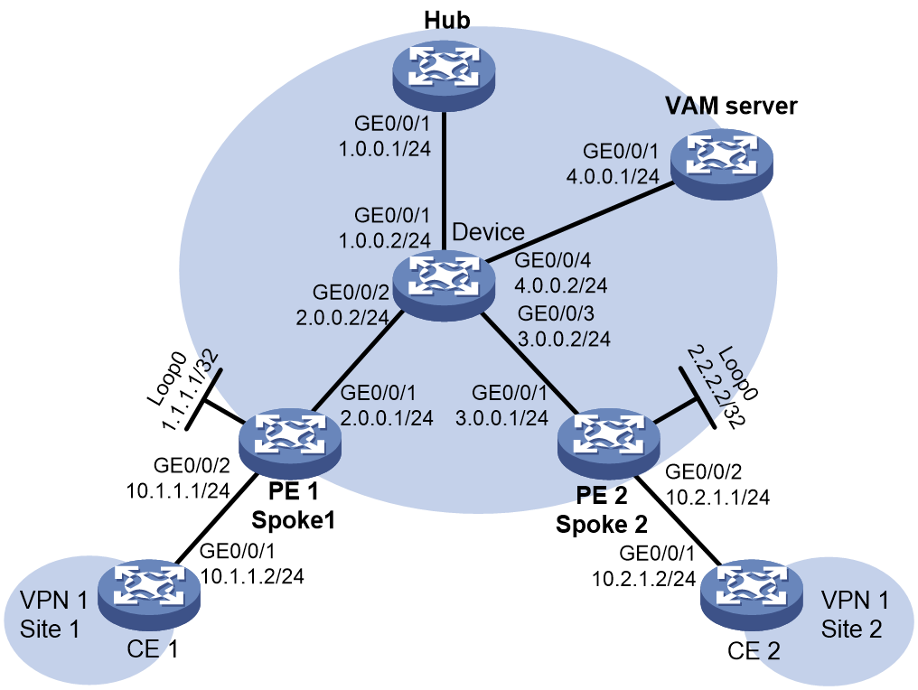
As shown in Figure 1, the specific networking requirements in this example are as follows:
· CE 1 and CE 2 belong to VPN 1.
· PE 1 and PE 2 are not only access devices for CEs to access the MPLS L3VPN network, but also spoke devices for the ADVPN network, setting up ADVPN tunnels with the hub.
· PE 1, PE 2 and Hub act as VAM clients and register their public and private network addresses with the VAM server.
Analysis
To ensure MPLS VPN traffic is transmitted across the ADVPN tunnel, perform the following configuration:
· Run OSPF on the backbone-facing interfaces of PEs, Device, Hub, and VAM server to ensure IP connectivity between the VAM clients and VAM server.
· Configure ADVPN on PEs and Hub, and establish ADVPN tunnels encapsulated in UDP between PEs and Hub, and between PE and PE.
· Configure IPsec on the ADVPN tunnels to ensure secure data transmission.
· For MPLS L3VPN, an ADVPN tunnel is a virtual link of MPLS L3VPN on the backbone network. To achieve public network routing connectivity for MPLS L3VPN, run OSPF on ADVPN tunnel interfaces and Loopback interfaces of the PE and Hub devices.
· To establish LDP LSPs over the ADVPN tunnels, enable MPLS and LDP on the ADVPN tunnel interfaces. The LDP LSPs serve as public network tunnels for MPLS L3VPN.
· Configure EBGP between PE and CE to exchange private network routes. On the CEs, redistribute direct routes into BGP.
· Establish MP-IBGP peers between the PEs to exchange BGP VPNv4 routes.
Software versions used
This configuration example was created and verified on R9141P16 of the MSR2630E-X1 router.
Data planning
Table 1 Configuration data
|
Configuration Item |
Data |
|
AS number of CE 1 |
65410 |
|
AS number of CE 2 |
65420 |
|
AS numbers of PE 1 and PE 2 |
100 |
|
VAM server address |
4.0.0.1 |
|
ADVPN tunnel interface address of the hub |
10.3.1.1/24 |
|
ADVPN tunnel interface address of PE 1 (Spoke 1) |
10.3.1.2/24 |
|
ADVPN tunnel interface address of PE 2 (Spoke 2). |
10.3.1.3/24 |
Procedures
Configuring the VAM server
Configuring interface IP addresses and unicast routing
# Assign an IP address to the interface.
<Sysname> system-view
[Sysname] sysname VAMserver
[VAMserver] interface gigabitethernet 0/0/1
[VAMserver-GigabitEthernet0/0/1] ip address 4.0.0.1 24
[VAMserver-GigabitEthernet0/0/1] quit
# Configure OSPF to achieve network layer connectivity.
[VAMserver] ospf
[VAMserver-ospf-1] area 0
[VAMserver-ospf-1-area-0.0.0.0] network 4.0.0.0 0.0.0.255
[VAMserver-ospf-1-area-0.0.0.0] quit
[VAMserver-ospf-1] quit
Configuring the VAM server
# Create ADVPN domain abc.
[VAMserver] vam server advpn-domain abc id 1
# Create hub group 0.
[VAMserver-vam-server-domain-abc] hub-group 0
# Specify the hub IPv4 private address.
[VAMserver-vam-server-domain-abc-hub-group-0] hub private-address 10.3.1.1
# Specify the IPv4 private network address range for spokes in the hub group.
[VAMserver-vam-server-domain-abc-hub-group-0] spoke private-address network 10.3.1.0 255.255.255.0
[VAMserver-vam-server-domain-abc-hub-group-0] quit
# Configure the preshared key of the VAM server as 123456.
[VAMserver-vam-server-domain-abc] pre-shared-key simple 123456
# Configure the VAM server to not authenticate VAM clients.
[VAMserver-vam-server-domain-abc] authentication-method none
# Enable the VAM server for the ADVPN domain.
[VAMserver-vam-server-domain-abc] server enable
[VAMserver-vam-server-domain-abc] quit
Configuring the hub
Configuring interface IP addresses and unicast routing
# Assign an IP address to the interface.
<Sysname> system-view
[Sysname] sysname Hub
[Hub] interface gigabitethernet 0/0/1
[Hub-GigabitEthernet0/0/1] ip address 1.0.0.1 24
[Hub-GigabitEthernet0/0/1] quit
# Configure OSPF to achieve network layer connectivity.
[Hub] ospf
[Hub-ospf-1] area 0
[Hub-ospf-1-area-0.0.0.0] network 1.0.0.0 0.0.0.255
[Hub-ospf-1-area-0.0.0.0] quit
[Hub-ospf-1] quit
Configuring the hub as a VAM client
# Create VAM client Hub.
[Hub] vam client name Hub
# Specify ADVPN domain abc for the VAM client.
[Hub-vam-client-Hub] advpn-domain abc
# Configure the preshared key of the VAM client as 123456.
[Hub-vam-client-Hub] pre-shared-key simple 123456
# Specify the IP address of the VAM server.
[Hub-vam-client-Hub] server primary ip-address 4.0.0.1
# Enable the VAM client.
[Hub-vam-client-Hub] client enable
[Hub-vam-client-Hub] quit
Configuring IPsec
# Configure an IKE profile.
[Hub] ike keychain abc
[Hub-ike-keychain-abc] pre-shared-key address 0.0.0.0 0.0.0.0 key simple 123456
[Hub-ike-keychain-abc] quit
[Hub] ike profile abc
[Hub-ike-profile-abc] keychain abc
[Hub-ike-profile-abc] quit
# Configure an IPsec profile.
[Hub] ipsec transform-set abc
[Hub-ipsec-transform-set-abc] encapsulation-mode transport
[Hub-ipsec-transform-set-abc] esp encryption-algorithm des-cbc
[Hub-ipsec-transform-set-abc] esp authentication-algorithm sha1
[Hub-ipsec-transform-set-abc] quit
[Hub] ipsec profile abc isakmp
[Hub-ipsec-profile-isakmp-abc] transform-set abc
[Hub-ipsec-profile-isakmp-abc] ike-profile abc
[Hub-ipsec-profile-isakmp-abc] quit
Configuring the ADVPN tunnel
Create a UDP-mode IPv4 ADVPN tunnel interface named Tunnel1, and configure an IP address for this interface.
[Hub] interface tunnel1 mode advpn udp
[Hub-Tunnel1] ip address 10.3.1.1 255.255.255.0
# Bind the VAM client to the IPv4 ADVPN tunnel interface.
[Hub-Tunnel1] vam client Hub
# Set the OSPF network type to broadcast to establish full-mesh ADVPN tunnels.
[Hub-Tunnel1] ospf network-type broadcast
# Configure the source interface of the IPv4 ADVPN tunnel.
[Hub-Tunnel1] source gigabitethernet 0/0/1
# Apply an IPsec profile to the IPv4 ADVPN tunnel to ensure secure data transmission.
[Hub-Tunnel1] tunnel protection ipsec profile abc
[Hub-Tunnel1] quit
Configuring OSPF to advertise the ADVPN tunnel interface address
# Configure OSPF to advertise the route for the ADVPN tunnel interface address. Make sure to use different OSPF processes to advertise the routes for Tunnel1 and GigabitEthernet 0/0/1.
[Hub] ospf 2
[Hub-ospf-2] area 0
[Hub-ospf-2-area-0.0.0.0] network 10.3.1.0 0.0.0.255
[Hub-ospf-2-area-0.0.0.0] quit
[Hub-ospf-2] quit
Configuring PE 1
Configuring interface IP addresses and unicast routing
# Assign an IP address to the interface.
<Sysname> system-view
[Sysname] sysname PE1
[PE1] interface loopback 0
[PE1-LoopBack0] ip address 1.1.1.1 32
[PE1-LoopBack0] quit
[PE1] interface gigabitethernet 0/0/1
[PE1-GigabitEthernet0/0/1] ip address 2.0.0.1 24
[PE1-GigabitEthernet0/0/1] quit
# Configure OSPF to achieve network layer connectivity.
[PE1] ospf
[PE1-ospf-1] area 0
[PE1-ospf-1-area-0.0.0.0] network 2.0.0.0 0.0.0.255
[PE1-ospf-1-area-0.0.0.0] quit
[PE1-ospf-1] quit
Configuring the VAM client
# Create VAM client Spoke1.
[PE1] vam client name Spoke1
# Specify ADVPN domain abc for the VAM client.
[PE1-vam-client-Spoke1] advpn-domain abc
# Configure a preshared key for the VAM client.
[PE1-vam-client-Spoke1] pre-shared-key simple 123456
# Specify the IP address of the VAM server.
[PE1-vam-client-Spoke1] server primary ip-address 4.0.0.1
# Enable the VAM client.
[PE1-vam-client-Spoke1] client enable
[PE1-vam-client-Spoke1] quit
Configuring IPsec
# Configure an IKE profile.
[PE1] ike keychain abc
[PE1-ike-keychain-abc] pre-shared-key address 0.0.0.0 0.0.0.0 key simple 123456
[PE1-ike-keychain-abc] quit
[PE1] ike profile abc
[PE1-ike-profile-abc] keychain abc
[PE1-ike-profile-abc] quit
# Configure an IPsec profile.
[PE1] ipsec transform-set abc
[PE1-ipsec-transform-set-abc] encapsulation-mode transport
[PE1-ipsec-transform-set-abc] esp encryption-algorithm des-cbc
[PE1-ipsec-transform-set-abc] esp authentication-algorithm sha1
[PE1-ipsec-transform-set-abc] quit
[PE1] ipsec profile abc isakmp
[PE1-ipsec-profile-isakmp-abc] transform-set abc
[PE1-ipsec-profile-isakmp-abc] ike-profile abc
[PE1-ipsec-profile-isakmp-abc] quit
Configuring the ADVPN tunnel
Create a UDP-mode IPv4 ADVPN tunnel interface named Tunnel1, and configure an IP address for this interface.
[PE1] interface tunnel1 mode advpn udp
[PE1-Tunnel1] ip address 10.3.1.2 255.255.255.0
# Bind the VAM client to the IPv4 ADVPN tunnel interface.
[PE1-Tunnel1] vam client Spoke1
# Set the OSPF network type to broadcast to establish full-mesh ADVPN tunnels. Set the DR priority of PE1 to 0 to exclude PE1 from DR/BDR election.
[PE1-Tunnel1] ospf network-type broadcast
[PE1-Tunnel1] ospf dr-priority 0
# Configure the source interface of the IPv4 ADVPN tunnel.
[PE1-Tunnel1] source gigabitethernet 0/0/1
# Apply an IPsec profile to the IPv4 ADVPN tunnel to ensure secure data transmission.
[PE1-Tunnel1] tunnel protection ipsec profile abc
[PE1-Tunnel1] quit
Configuring OSPF to advertise the ADVPN tunnel interface address
# Configure OSPF to advertise routes for the ADVPN tunnel interface and Loopback interface. Make sure to use different OSPF processes to advertise the routes for Tunnel1 and GigabitEthernet 0/0/1.
[PE1] ospf 2
[PE1-ospf-2] area 0
[PE1-ospf-2-area-0.0.0.0] network 1.1.1.1 0.0.0.0
[PE1-ospf-2-area-0.0.0.0] network 10.3.1.0 0.0.0.255
[PE1-ospf-2-area-0.0.0.0] quit
[PE1-ospf-2] quit
Configuring an MPLS LSR ID and enabling MPLS and MPLS LDP on nodes
[PE1] mpls lsr-id 1.1.1.1
[PE1] mpls ldp
[PE1-ldp] quit
[PE1] interface tunnel1 mode advpn udp
[PE1-Tunnel1] mpls enable
[PE1-Tunnel1] mpls ldp enable
[PE1-Tunnel1] quit
Configuring MP-IBGP peering between PE 1 and PE 2 to exchange VPNv4 routes
[PE1] bgp 100
[PE1-bgp-default] peer 2.2.2.2 as-number 100
[PE1-bgp-default] peer 2.2.2.2 connect-interface loopback 0
[PE1-bgp-default] address-family vpnv4
[PE1-bgp-default-vpnv4] peer 2.2.2.2 enable
[PE1-bgp-default-vpnv4] quit
Configuring a VPN instance
# Create VPN instance vpn1 and configure the RD and RT of the VPN instance.
[PE1] ip vpn-instance vpn1
[PE1-vpn-instance-vpn1] route-distinguisher 1:1
[PE1-vpn-instance-vpn1] vpn-target 1:1 import-extcommunity
[PE1-vpn-instance-vpn1] vpn-target 1:1 export-extcommunity
[PE1-vpn-instance-vpn1] quit
# Bind interface GigabitEthernet 0/0/2 to VPN instance vpn1 and configure an IP address for this interface.
[PE1] interface gigabitethernet 0/0/2
[PE1-GigabitEthernet0/0/2] ip binding vpn-instance vpn1
[PE1-GigabitEthernet0/0/2] ip address 10.1.1.1 24
[PE1-GigabitEthernet0/0/2] quit
Configuring PE 1 to establish EBGP peering with CE 1 to exchange private network routes
[PE1] bgp 100
[PE1-bgp-default] ip vpn-instance vpn1
[PE1-bgp-default-vpn1] peer 10.1.1.2 as-number 65410
[PE1-bgp-default-vpn1] address-family ipv4 unicast
[PE1-bgp-default-ipv4-vpn1] peer 10.1.1.2 enable
[PE1-bgp-default-ipv4-vpn1] quit
[PE1-bgp-default-vpn1] quit
Configuring PE 2
Configuring interface IP addresses and unicast routing
# Assign an IP address to the interface.
<Sysname> system-view
[Sysname] sysname PE2
[PE2] interface loopback 0
[PE2-LoopBack0] ip address 2.2.2.2 32
[PE2-LoopBack0] quit
[PE2] interface gigabitethernet 0/0/1
[PE2-GigabitEthernet0/0/1] ip address 3.0.0.1 24
[PE2-GigabitEthernet0/0/1] quit
# Configure OSPF to achieve network layer connectivity.
[PE2] ospf
[PE2-ospf-1] area 0
[PE2-ospf-1-area-0.0.0.0] network 3.0.0.0 0.0.0.255
[PE2-ospf-1-area-0.0.0.0] quit
[PE2-ospf-1] quit
Configuring the VAM client
# Create VAM client Spoke2.
[PE2] vam client name Spoke2
# Specify ADVPN domain abc for the VAM client.
[PE2-vam-client-Spoke2] advpn-domain abc
# Configure a preshared key for the VAM client.
[PE2-vam-client-Spoke2] pre-shared-key simple 123456
# Specify the IP address of the VAM server.
[PE2-vam-client-Spoke2] server primary ip-address 4.0.0.1
# Enable the VAM client.
[PE2-vam-client-Spoke2] client enable
[PE2-vam-client-Spoke2] quit
Configuring IPsec
# Configure an IKE profile.
[PE2] ike keychain abc
[PE2-ike-keychain-abc] pre-shared-key address 0.0.0.0 0.0.0.0 key simple 123456
[PE2-ike-keychain-abc] quit
[PE2] ike profile abc
[PE2-ike-profile-abc] keychain abc
[PE2-ike-profile-abc] quit
# Configure an IPsec profile.
[PE2] ipsec transform-set abc
[PE2-ipsec-transform-set-abc] encapsulation-mode transport
[PE2-ipsec-transform-set-abc] esp encryption-algorithm des-cbc
[PE2-ipsec-transform-set-abc] esp authentication-algorithm sha1
[PE2-ipsec-transform-set-abc] quit
[PE2] ipsec profile abc isakmp
[PE2-ipsec-profile-isakmp-abc] transform-set abc
[PE2-ipsec-profile-isakmp-abc] ike-profile abc
[PE2-ipsec-profile-isakmp-abc] quit
Configuring the ADVPN tunnel
Create a UDP-mode IPv4 ADVPN tunnel interface named Tunnel1, and configure an IP address for this interface.
[PE2] interface tunnel1 mode advpn udp
[PE2-Tunnel1] ip address 10.3.1.3 255.255.255.0
# Bind the VAM client to the IPv4 ADVPN tunnel interface.
[PE2-Tunnel1] vam client Spoke2
# Set the OSPF network type to broadcast to establish full-mesh ADVPN tunnels. Set the DR priority of PE2 to 0 to exclude PE2 from DR/BDR election.
[PE2-Tunnel1] ospf network-type broadcast
[PE2-Tunnel1] ospf dr-priority 0
# Configure the source interface of the IPv4 ADVPN tunnel.
[PE2-Tunnel1] source gigabitethernet 0/0/1
# Apply an IPsec profile to the IPv4 ADVPN tunnel to ensure secure data transmission.
[PE2-Tunnel1] tunnel protection ipsec profile abc
[PE2-Tunnel1] quit
Configuring OSPF to advertise the ADVPN tunnel interface address
# Configure OSPF to advertise routes for the ADVPN tunnel interface and Loopback interface. Make sure to use different OSPF processes to advertise the routes for Tunnel1 and GigabitEthernet 0/0/1.
[PE2] ospf 2
[PE2-ospf-2] area 0
[PE2-ospf-2-area-0.0.0.0] network 2.2.2.2 0.0.0.0
[PE2-ospf-2-area-0.0.0.0] network 10.3.1.0 0.0.0.255
[PE2-ospf-2-area-0.0.0.0] quit
[PE2-ospf-2] quit
Configuring an MPLS LSR ID and enabling MPLS and MPLS LDP on nodes
[PE2] mpls lsr-id 2.2.2.2
[PE2] mpls ldp
[PE2-ldp] quit
[PE2] interface tunnel1 mode advpn udp
[PE2-Tunnel1] mpls enable
[PE2-Tunnel1] mpls ldp enable
[PE2-Tunnel1] quit
Configuring MP-IBGP peering between PE 1 and PE 2 to exchange VPNv4 routes
[PE2] bgp 100
[PE2-bgp-default] peer 1.1.1.1 as-number 100
[PE2-bgp-default] peer 1.1.1.1 connect-interface loopback 0
[PE2-bgp-default] address-family vpnv4
[PE2-bgp-default-vpnv4] peer 1.1.1.1 enable
[PE2-bgp-default-vpnv4] quit
Configuring a VPN instance
# Create VPN instance vpn1 and configure the RD and RT of the VPN instance.
[PE2] ip vpn-instance vpn1
[PE2-vpn-instance-vpn1] route-distinguisher 1:1
[PE2-vpn-instance-vpn1] vpn-target 1:1 import-extcommunity
[PE2-vpn-instance-vpn1] vpn-target 1:1 export-extcommunity
[PE2-vpn-instance-vpn1] quit
# Bind interface GigabitEthernet 0/0/2 to VPN instance vpn1 and configure an IP address for this interface.
[PE2] interface gigabitethernet 0/0/2
[PE2-GigabitEthernet0/0/2] ip binding vpn-instance vpn1
[PE2-GigabitEthernet0/0/2] ip address 10.2.1.1 24
[PE2-GigabitEthernet0/0/2] quit
Configuring PE 1 to establish EBGP peering with CE 1 to exchange private network routes
[PE2] bgp 100
[PE2-bgp-default] ip vpn-instance vpn1
[PE2-bgp-default-vpn1] peer 10.2.1.2 as-number 65420
[PE2-bgp-default-vpn1] address-family ipv4 unicast
[PE2-bgp-default-ipv4-vpn1] peer 10.2.1.2 enable
[PE2-bgp-default-ipv4-vpn1] quit
[PE2-bgp-default-vpn1] quit
Configuring Device
Specifying an IP address
# Assign an IP address to the interface.
<Sysname> system-view
[Sysname] sysname Device
[Device] interface gigabitethernet 0/0/1
[Device-GigabitEthernet0/0/1] ip address 1.0.0.2 24
[Device-GigabitEthernet0/0/1] quit
[Device] interface gigabitethernet 0/0/2
[Device-GigabitEthernet0/0/2] ip address 2.0.0.2 24
[Device-GigabitEthernet0/0/2] quit
[Device] interface gigabitethernet 0/0/3
[Device-GigabitEthernet0/0/3] ip address 3.0.0.2 24
[Device-GigabitEthernet0/0/3] quit
[Device] interface gigabitethernet 0/0/4
[Device-GigabitEthernet0/0/4] ip address 4.0.0.2 24
[Device-GigabitEthernet0/0/4] quit
Configuring unicast routing
# Configure OSPF to achieve network layer connectivity.
[Device] ospf
[Device-ospf-1] area 0
[Device-ospf-1-area-0.0.0.0] network 1.0.0.0 0.0.0.255
[Device-ospf-1-area-0.0.0.0] network 2.0.0.0 0.0.0.255
[Device-ospf-1-area-0.0.0.0] network 3.0.0.0 0.0.0.255
[Device-ospf-1-area-0.0.0.0] network 4.0.0.0 0.0.0.255
[Device-ospf-1-area-0.0.0.0] quit
[Device-ospf-1] quit
Configuring CE 1
Specifying an IP address
<Sysname> system-view
[Sysname] sysname CE1
[CE1] interface gigabitethernet 0/0/1
[CE1-GigabitEthernet0/0/1] ip address 10.1.1.2 24
[CE1-GigabitEthernet0/0/1] quit
Establishing EBGP peering between PE and CE to redistribute direct routes into BGP.
[CE1] bgp 65410
[CE1-bgp-default] peer 10.1.1.1 as-number 100
[CE1-bgp-default] address-family ipv4 unicast
[CE1-bgp-default-ipv4] peer 10.1.1.1 enable
[CE1-bgp-default-ipv4] import-route direct
[CE1-bgp-default-ipv4] quit
[CE1-bgp-default] quit
Configuring CE 2
Specifying an IP address
<Sysname> system-view
[Sysname] sysname CE2
[CE2] interface gigabitethernet 0/0/1
[CE2-GigabitEthernet0/0/1] ip address 10.2.1.2 24
[CE2-GigabitEthernet0/0/1] quit
Establishing EBGP peering between PE and CE to redistribute direct routes into BGP
[CE2] bgp 65420
[CE2-bgp-default] peer 10.2.1.1 as-number 100
[CE2-bgp-default] address-family ipv4 unicast
[CE2-bgp-default-ipv4] peer 10.2.1.1 enable
[CE2-bgp-default-ipv4] quit
[CE2-bgp-default] quit
Verifying the configuration
Verifying that ADVPN tunnels are established successfully
# Display IPv4 address mapping information for all VAM clients registered with the VAM server. The output shows that Hub, Spoke 1, and Spoke 2 have all registered their address mapping information with the VAM server.
<VAMserver> display vam server address-map
ADVPN domain name: abc
Total private address mappings: 3
Group Private address Public address Type NAT Holding time
0 10.3.1.1 1.0.0.1 Hub No 0H 43M 43S
0 10.3.1.2 2.0.0.1 Spoke No 0H 44M 40S
0 10.3.1.3 3.0.0.1 Spoke No 0H 44M 53S
# On PE 1, ping the private network address 10.3.1.3 of PE 2, and it can be pinged successfully.
<PE1> ping 10.3.1.3
Ping 10.3.1.3 (10.3.1.3): 56 data bytes, press CTRL_C to break
56 bytes from 10.3.1.3: icmp_seq=0 ttl=255 time=4.000 ms
56 bytes from 10.3.1.3: icmp_seq=1 ttl=255 time=0.000 ms
56 bytes from 10.3.1.3: icmp_seq=2 ttl=255 time=0.000 ms
56 bytes from 10.3.1.3: icmp_seq=3 ttl=255 time=0.000 ms
56 bytes from 10.3.1.3: icmp_seq=4 ttl=255 time=1.000 ms
--- Ping statistics for 10.3.1.3 ---
5 packets transmitted, 5 packets received, 0.0% packet loss
round-trip min/avg/max/std-dev = 0.000/1.000/4.000/1.549 ms
# Display IPv4 ADVPN tunnel information on Hub, PE 1, and PE 2. The output shows that ADVPN tunnels have been established between hub and spoke, as well as between spoke and spoke.
<Hub> display advpn session
Interface : Tunnel1
Number of sessions: 2
Private address Public address Port Type State Holding time
10.3.1.2 2.0.0.1 18001 H-S Success 0H 41M 35S
10.3.1.3 3.0.0.1 18001 H-S Success 0H 41M 36S
<PE1> display advpn session
Interface : Tunnel1
Number of sessions: 2
Private address Public address Port Type State Holding time
10.3.1.1 1.0.0.1 18001 S-H Success 0H 44M 7S
10.3.1.3 3.0.0.1 18001 S-S Success 0H 40M 2S
<PE2> display advpn session
Interface : Tunnel1
Number of sessions: 2
Private address Public address Port Type State Holding time
10.3.1.1 1.0.0.1 18001 S-H Success 0H 48M 41S
10.3.1.2 2.0.0.1 18001 S-S Success 0H 44M 31S
Verifying that PEs have learned the private network route from the peer and CEs can ping each other
# Execute the display bgp peer vpnv4 command on PEs. The output shows that PE 1 and PE 2 have established a BGP VPNv4 peer relationship.
<PE1> display bgp peer vpnv4
BGP local router ID: 1.1.1.1
Local AS number: 100
Total number of peers: 1 Peers in established state: 1
* - Dynamically created peer
Peer AS MsgRcvd MsgSent OutQ PrefRcv Up/Down State
2.2.2.2 100 30 26 0 1 00:20:34 Established
<PE2> display bgp peer vpnv4
BGP local router ID: 2.2.2.2
Local AS number: 100
Total number of peers: 1 Peers in established state: 1
* - Dynamically created peer
Peer AS MsgRcvd MsgSent OutQ PrefRcv Up/Down State
1.1.1.1 100 30 35 0 1 00:24:36 Established
# Execute the display bgp routing-table vpnv4 command on PEs. The output shows that the PEs have learned private network routes from the remote CEs through BGP VPNv4.
<PE1> display bgp routing-table vpnv4
BGP local router ID is 1.1.1.1
Status codes: * - valid, > - best, d - dampened, h - history,
s - suppressed, S - stale, i - internal, e - external,
a - additional-path
Origin: i - IGP, e - EGP, ? - incomplete
Total number of routes from all PEs: 1
Route distinguisher: 1:1(vpn1)
Total number of routes: 2
Network NextHop MED LocPrf PrefVal Path/Ogn
* >e 10.1.1.0/24 10.1.1.2 0 0 65410?
* >i 10.2.1.0/24 2.2.2.2 0 100 0 65420?
<PE2> display bgp routing-table vpnv4
BGP local router ID is 2.2.2.2
Status codes: * - valid, > - best, d - dampened, h - history,
s - suppressed, S - stale, i - internal, e - external,
a - additional-path
Origin: i - IGP, e - EGP, ? - incomplete
Total number of routes from all PEs: 1
Route distinguisher: 1:1(vpn1)
Total number of routes: 2
Network NextHop MED LocPrf PrefVal Path/Ogn
* >i 10.1.1.0/24 1.1.1.1 0 100 0 65410?
* >e 10.2.1.0/24 10.2.1.2 0 0 65420?
# On PEs, display the FIB entries in VPN instance vpn1. The output shows that the outgoing interface for the route to the remote CE is ADVPN tunnel interface Tunnel1, and the remote PE has assigned a private network label to that route.
<PE1> display fib vpn-instance vpn1
Route destination count: 9
Directly-connected host count: 1
Flag:
U:Usable G:Gateway H:Host B:Blackhole D:Dynamic S:Static
R:Relay F:FRR
Destination/Mask Nexthop Flag OutInterface/Token Label
0.0.0.0/32 127.0.0.1 UH InLoop0 Null
10.1.1.0/24 10.1.1.1 U GE0/0/2 Null
10.1.1.1/32 127.0.0.1 UH InLoop0 Null
10.1.1.2/32 10.1.1.2 UH GE0/0/2 Null
10.1.1.255/32 10.1.1.1 UBH GE0/0/2 Null
10.2.1.0/24 2.2.2.2 UGR 1 24256
127.0.0.0/8 127.0.0.1 U InLoop0 Null
127.0.0.1/32 127.0.0.1 UH InLoop0 Null
127.255.255.255/32 127.0.0.1 UH InLoop0 Null
255.255.255.255/32 127.0.0.1 UH InLoop0 Null
<PE2> display fib vpn-instance vpn1
Route destination count: 9
Directly-connected host count: 1
Flag:
U:Usable G:Gateway H:Host B:Blackhole D:Dynamic S:Static
R:Relay F:FRR
Destination/Mask Nexthop Flag OutInterface/Token Label
0.0.0.0/32 127.0.0.1 UH InLoop0 Null
10.1.1.0/24 1.1.1.1 UGR 1 24256
10.2.1.0/24 10.2.1.1 U GE0/0/2 Null
10.2.1.1/32 127.0.0.1 UH InLoop0 Null
10.2.1.2/32 10.2.1.2 UH GE0/0/2 Null
10.2.1.255/32 10.2.1.1 UBH GE0/0/2 Null
127.0.0.0/8 127.0.0.1 U InLoop0 Null
127.0.0.1/32 127.0.0.1 UH InLoop0 Null
127.255.255.255/32 127.0.0.1 UH InLoop0 Null
255.255.255.255/32 127.0.0.1 UH InLoop0 Null
# Verify that the CE devices can ping each other.
<CE1> ping 10.2.1.2
Ping 10.2.1.2 (10.2.1.2): 56 data bytes, press CTRL_C to break
56 bytes from 10.2.1.2: icmp_seq=0 ttl=253 time=2.000 ms
56 bytes from 10.2.1.2: icmp_seq=1 ttl=253 time=1.000 ms
56 bytes from 10.2.1.2: icmp_seq=2 ttl=253 time=2.000 ms
56 bytes from 10.2.1.2: icmp_seq=3 ttl=253 time=1.000 ms
56 bytes from 10.2.1.2: icmp_seq=4 ttl=253 time=2.000 ms
--- Ping statistics for 10.2.1.2 ---
5 packet(s) transmitted, 5 packet(s) received, 0.0% packet loss
round-trip min/avg/max/std-dev = 1.000/1.600/2.000/0.490 ms
Configuration files
· VAM server
#
sysname VAMserver
#
ospf 1
area 0.0.0.0
network 4.0.0.0 0.0.0.255
#
interface GigabitEthernet0/0/1
port link-mode route
combo enable copper
ip address 4.0.0.1 255.255.255.0
#
vam server advpn-domain abc id 1
pre-shared-key cipher $c$3$4g3dSoFtvWfi8HvmFfTt2RItcU9oDrJnYg==
authentication-method none
server enable
hub-group 0
hub private-address 10.3.1.1
spoke private-address range 10.3.1.0 10.3.1.255
#
return
· Hub
#
sysname Hub
#
ospf 1
area 0.0.0.0
network 1.0.0.0 0.0.0.255
#
ospf 2
area 0.0.0.0
network 10.3.1.0 0.0.0.255
#
interface GigabitEthernet0/0/1
port link-mode route
combo enable copper
ip address 1.0.0.1 255.255.255.0
#
interface Tunnel1 mode advpn udp
ip address 10.3.1.1 255.255.255.0
ospf network-type broadcast
source GigabitEthernet0/0/1
tunnel protection ipsec profile abc
vam client Hub
#
ipsec transform-set abc
encapsulation-mode transport
esp encryption-algorithm des-cbc
esp authentication-algorithm sha1
#
ipsec profile abc isakmp
transform-set abc
ike-profile abc
#
ike profile abc
keychain abc
#
ike keychain abc
pre-shared-key address 0.0.0.0 0.0.0.0 key cipher $c$3$MTshF3PbSXutZ6ba3rQ445mP6m1jyPXuMg==
#
vam client name Hub
advpn-domain abc
server primary ip-address 4.0.0.1
pre-shared-key cipher $c$3$t3kfwOkdYFK57jEODcpQHf943u+98JdbkA==
client enable
#
return
· PE 1
#
sysname PE1
#
ip vpn-instance vpn1
route-distinguisher 1:1
vpn-target 1:1 import-extcommunity
vpn-target 1:1 export-extcommunity
#
ospf 1
area 0.0.0.0
network 2.0.0.0 0.0.0.255
#
ospf 2
area 0.0.0.0
network 1.1.1.1 0.0.0.0
network 10.3.1.0 0.0.0.255
#
mpls lsr-id 1.1.1.1
#
mpls ldp
#
interface LoopBack0
ip address 1.1.1.1 255.255.255.255
#
interface GigabitEthernet0/0/1
port link-mode route
combo enable copper
ip address 2.0.0.1 255.255.255.0
#
interface GigabitEthernet0/0/2
port link-mode route
combo enable copper
ip binding vpn-instance vpn1
ip address 10.1.1.1 255.255.255.0
#
interface Tunnel1 mode advpn udp
ip address 10.3.1.2 255.255.255.0
ospf network-type broadcast
ospf dr-priority 0
mpls enable
mpls ldp enable
source GigabitEthernet0/0/1
tunnel protection ipsec profile abc
vam client Spoke1
#
bgp 100
peer 2.2.2.2 as-number 100
peer 2.2.2.2 connect-interface LoopBack0
#
address-family vpnv4
peer 2.2.2.2 enable
#
ip vpn-instance vpn1
peer 10.1.1.2 as-number 65410
#
address-family ipv4 unicast
peer 10.1.1.2 enable
#
ipsec transform-set abc
encapsulation-mode transport
esp encryption-algorithm des-cbc
esp authentication-algorithm sha1
#
ipsec profile abc isakmp
transform-set abc
ike-profile abc
#
ike profile abc
keychain abc
#
ike keychain abc
pre-shared-key address 0.0.0.0 0.0.0.0 key cipher $c$3$D4z85zTTQkoSKg6QcP/yNRcRyYzT5Rci1w==
#
vam client name Spoke1
advpn-domain abc
server primary ip-address 4.0.0.1
pre-shared-key cipher $c$3$kdGtUDsS34JSBmeagv0gg/+bUzGX1jo/nQ==
client enable
#
return
· PE 2
#
sysname PE2
#
ip vpn-instance vpn1
route-distinguisher 1:1
vpn-target 1:1 import-extcommunity
vpn-target 1:1 export-extcommunity
#
ospf 1
area 0.0.0.0
network 3.0.0.0 0.0.0.255
#
ospf 2
area 0.0.0.0
network 2.2.2.2 0.0.0.0
network 10.3.1.0 0.0.0.255
#
mpls lsr-id 2.2.2.2
#
mpls ldp
#
interface LoopBack0
ip address 2.2.2.2 255.255.255.255
#
interface GigabitEthernet0/0/1
port link-mode route
combo enable copper
ip address 3.0.0.1 255.255.255.0
#
interface GigabitEthernet0/0/2
port link-mode route
combo enable copper
ip binding vpn-instance vpn1
ip address 10.2.1.1 255.255.255.0
#
interface Tunnel1 mode advpn udp
ip address 10.3.1.3 255.255.255.0
ospf network-type broadcast
ospf dr-priority 0
mpls enable
mpls ldp enable
source GigabitEthernet0/0/1
tunnel protection ipsec profile abc
vam client Spoke2
#
bgp 100
peer 1.1.1.1 as-number 100
peer 1.1.1.1 connect-interface LoopBack0
#
address-family vpnv4
peer 1.1.1.1 enable
#
ip vpn-instance vpn1
peer 10.2.1.2 as-number 65420
#
address-family ipv4 unicast
peer 10.2.1.2 enable
#
ipsec transform-set abc
encapsulation-mode transport
esp encryption-algorithm des-cbc
esp authentication-algorithm sha1
#
ipsec profile abc isakmp
transform-set abc
ike-profile abc
#
ike profile abc
keychain abc
#
ike keychain abc
pre-shared-key address 0.0.0.0 0.0.0.0 key cipher $c$3$xDmL61HQY2KOy0pQqPpkwXNZD81U77cPow==
#
vam client name Spoke2
advpn-domain abc
server primary ip-address 4.0.0.1
pre-shared-key cipher $c$3$JmWbOY0L4qmNKYkMvY2ve3/cbDz7lVFuKg==
client enable
#
return
· Device
#
sysname Device
#
ospf 1
area 0.0.0.0
network 1.0.0.0 0.0.0.255
network 2.0.0.0 0.0.0.255
network 3.0.0.0 0.0.0.255
network 4.0.0.0 0.0.0.255
#
interface GigabitEthernet0/0/1
port link-mode route
combo enable copper
ip address 1.0.0.2 255.255.255.0
#
interface GigabitEthernet0/0/2
port link-mode route
combo enable copper
ip address 2.0.0.2 255.255.255.0
#
interface GigabitEthernet0/0/3
port link-mode route
combo enable copper
ip address 3.0.0.2 255.255.255.0
#
interface GigabitEthernet0/0/4
port link-mode route
combo enable copper
ip address 4.0.0.2 255.255.255.0
#
return
· CE 1
#
sysname CE1
#
interface GigabitEthernet0/0/1
port link-mode route
combo enable copper
ip address 10.1.1.2 255.255.255.0
#
bgp 65410
peer 10.1.1.1 as-number 100
#
address-family ipv4 unicast
import-route direct
peer 10.1.1.1 enable
#
return
· CE 2
#
sysname CE2
#
interface GigabitEthernet0/0/1
port link-mode route
combo enable copper
ip address 10.2.1.2 255.255.255.0
#
bgp 65420
peer 10.2.1.1 as-number 100
#
address-family ipv4 unicast
import-route direct
peer 10.2.1.1 enable
#
return
Example: Configuring IPv6 LDP over GRE-encapsulated ADVPN
Network configuration
Enterprise branches use dynamic addresses to access the public network, and establish ADVPN tunnels between the hub and spokes but not between spokes, forming a hub-spoke network. This ensures uninterrupted communication between branches despite changes in public network addresses.
Meanwhile, the enterprise branches hope to forward traffic through IPv6 LDP LSPs. For this purpose, the branches must establish the IPv6 LDP LSPs over the ADVPN tunnels in the public network.
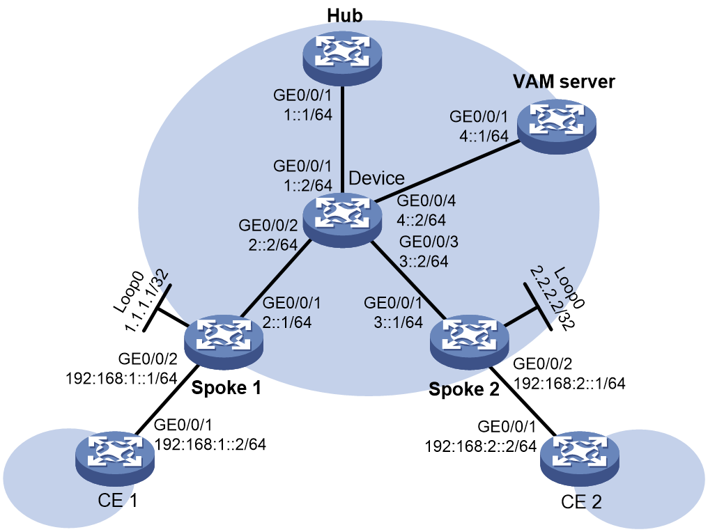
As shown in Figure 2, the specific networking requirements in this example are as follows:
· Spoke 1 and Spoke 2 establish ADVPN tunnels with Hub.
· Configure IPv6 LDP on the ADVPN tunnels to establish IPv6 LDP LSPs over the ADVPN tunnels.
· Spoke 1, Spoke 2 and Hub act as VAM clients to register their public and private network addresses with the VAM server.
Analysis
To establish IPv6 LDP LSPs across ADVPN tunnels, perform the following configuration:
· Run OSPFv3 on the backbone-facing interfaces of Spokes, Device, Hub, and VAM server to ensure routing connectivity between the VAM clients and VAM server.
· Configure ADVPN on Spokes and Hub to establish ADVPN tunnels using GRE encapsulation between Spokes and Hub.
· Configure IPsec on the ADVPN tunnels to ensure secure data transmission.
· For IPv6 LDP, an ADVPN tunnel is a virtual link on the backbone network. To enable private network routing between sites and communication between sites through ADVPN tunnels, a routing protocol (OSPFv3 in this example) must be configured on the ADVPN tunnel interfaces on Spoke and Hub devices.
· To establish IPv6 LDP LSPs over the ADVPN tunnels, enable MPLS and LDP on the ADVPN tunnel interfaces of Spoke and Hub devices.
Software versions used
This configuration example was created and verified on R9141P16 of the MSR2630E-X1 router.
Data planning
Table 2 Configuration data
|
Configuration Item |
Data |
|
VAM server address |
4::1 |
|
ADVPN tunnel interface address of the hub |
192:168:3::1/64 |
|
ADVPN tunnel interface address of Spoke 1 |
192:168:3::2/64 |
|
ADVPN tunnel interface address of Spoke 2 |
192:168:3::3/64 |
Procedures
Configuring the VAM server
Configuring interface IPv6 addresses and unicast routing
# Create OSPFv3 process 1 in area 0, and configure the router ID of the node.
<Sysname> system-view
[Sysname] sysname VAMserver
[VAMserver] ospfv3
[VAMserver-ospfv3-1] router-id 4.4.4.4
[VAMserver-ospfv3-1] area 0
[VAMserver-ospfv3-1-area-0.0.0.0] quit
[VAMserver-ospfv3-1] quit
# Configure the IPv6 address of the interface and enable OSPFv3 on the interface.
[VAMserver] interface gigabitethernet 0/0/1
[VAMserver-GigabitEthernet0/0/1] ipv6 address 4::1/64
[VAMserver-GigabitEthernet0/0/1] ospfv3 1 area 0.0.0.0
[VAMserver-GigabitEthernet0/0/1] quit
Configuring the VAM server
# Create ADVPN domain abc.
[VAMserver] vam server advpn-domain abc id 1
# Create hub group 0.
[VAMserver-vam-server-domain-abc] hub-group 0
# Specify the hub IPv6 private address.
[VAMserver-vam-server-domain-abc-hub-group-0] hub ipv6 private-address 192:168:3::1
# Specify the IPv6 private network address range for spokes in the hub group.
[VAMserver-vam-server-domain-abc-hub-group-0] spoke ipv6 private-address network 192:168:: 32
[VAMserver-vam-server-domain-abc-hub-group-0] quit
# Configure the preshared key of the VAM server as 123456.
[VAMserver-vam-server-domain-abc] pre-shared-key simple 123456
# Configure the VAM server to not authenticate VAM clients.
[VAMserver-vam-server-domain-abc] authentication-method none
# Enable the VAM server for the ADVPN domain.
[VAMserver-vam-server-domain-abc] server enable
[VAMserver-vam-server-domain-abc] quit
Configuring the hub
Configuring interface IPv6 addresses and unicast routing
# Create OSPFv3 process 1 in area 0, and configure the router ID of the node.
<Sysname> system-view
[Sysname] sysname Hub
[Hub] ospfv3
[Hub-ospfv3-1] router-id 5.5.5.5
[Hub-ospfv3-1] area 0
[Hub-ospfv3-1-area-0.0.0.0] quit
[Hub-ospfv3-1] quit
# Configure the IPv6 address of the interface and enable OSPFv3 on the interface.
[Hub] interface gigabitethernet 0/0/1
[Hub-GigabitEthernet0/0/1] ipv6 address 1::1 64
[Hub-GigabitEthernet0/0/1] ospfv3 1 area 0.0.0.0
[Hub-GigabitEthernet0/0/1] quit
Configuring the hub as a VAM client
# Create VAM client Hub.
[Hub] vam client name Hub
# Specify ADVPN domain abc for the VAM client.
[Hub-vam-client-Hub] advpn-domain abc
# Configure the preshared key of the VAM client as 123456.
[Hub-vam-client-Hub] pre-shared-key simple 123456
# Specify the IP address of the VAM server.
[Hub-vam-client-Hub] server primary ipv6-address 4::1
# Enable the VAM client.
[Hub-vam-client-Hub] client enable
[Hub-vam-client-Hub] quit
Configuring IPsec
# Configure an IKE profile.
[Hub] ike keychain abc
[Hub-ike-keychain-abc] pre-shared-key address ipv6 :: 0 key simple 123456
[Hub-ike-keychain-abc] quit
[Hub] ike profile abc
[Hub-ike-profile-abc] keychain abc
[Hub-ike-profile-abc] quit
# Configure an IPsec profile.
[Hub] ipsec transform-set abc
[Hub-ipsec-transform-set-abc] encapsulation-mode transport
[Hub-ipsec-transform-set-abc] esp encryption-algorithm des-cbc
[Hub-ipsec-transform-set-abc] esp authentication-algorithm sha1
[Hub-ipsec-transform-set-abc] quit
[Hub] ipsec profile abc isakmp
[Hub-ipsec-profile-isakmp-abc] transform-set abc
[Hub-ipsec-profile-isakmp-abc] ike-profile abc
[Hub-ipsec-profile-isakmp-abc] quit
Configuring the ADVPN tunnel
Create a GRE-mode IPv6 ADVPN tunnel interface named Tunnel1, and configure an IPv6 address for this interface.
[Hub] interface tunnel1 mode advpn gre ipv6
[Hub-Tunnel1] ipv6 address 192:168:3::1 64
[Hub-Tunnel1] ipv6 address fe80::1 link-local
# Bind the VAM client to the IPv6 ADVPN tunnel interface.
[Hub-Tunnel1] vam ipv6 client Hub
# Configure OSPF network type as P2MP to form a hub-spoke network, where ADVPN tunnels are established only between hub and spokes, and no ADVPN tunnels are established between spokes.
[Hub-Tunnel1] ospfv3 network-type p2mp
# Configure the source interface of the IPv6 ADVPN tunnel.
[Hub-Tunnel1] source gigabitethernet 0/0/1
# Apply an IPsec profile to the IPv4 ADVPN tunnel to ensure secure data transmission.
[Hub-Tunnel1] tunnel protection ipsec profile abc
[Hub-Tunnel1] quit
Configuring OSPFv3 to advertise the ADVPN tunnel interface address
# Configure OSPFv3 to advertise the route for the ADVPN tunnel interface address. Make sure to use different OSPFv3 processes to advertise the routes for Tunnel1 and GigabitEthernet 0/0/1.
[Hub] ospfv3 2
[Hub-ospfv3-2] router-id 5.5.5.5
[Hub-ospfv3-2] area 0
[Hub-ospfv3-2-area-0.0.0.0] quit
[Hub-ospfv3-2] quit
[Hub] interface tunnel1
[Hub-Tunnel1] ospfv3 2 area 0.0.0.0
[Hub-Tunnel1] quit
Configuring an MPLS LSR ID and enabling MPLS and MPLS LDP on nodes
# Enable MPLS and MPLS LDP, and configure all IPv6 routes to trigger the establishment of IPv6 LDP LSPs.
[Hub] mpls lsr-id 5.5.5.5
[Hub] mpls ldp
[Hub-ldp] ipv6 lsp-trigger all
[Hub-ldp] quit
# Enable MPLS and MPLS LDP on interface Tunnel1, and configure LDP transport address as the address of Tunnel1.
[Hub] interface tunnel1
[Hub-Tunnel1] mpls enable
[Hub-Tunnel1] mpls ldp ipv6 enable
[Hub-Tunnel1] mpls ldp transport-address 192:168:3::1
[Hub-Tunnel1] quit
Configuring Spoke 1
Configuring interface IPv6 addresses and unicast routing
# Create OSPFv3 process 1 in area 0, and configure the router ID of the node.
<Sysname> system-view
[Sysname] sysname Spoke1
[Spoke1] ospfv3
[Spoke1-ospfv3-1] router-id 1.1.1.1
[Spoke1-ospfv3-1] area 0
[Spoke1-ospfv3-1-area-0.0.0.0] quit
[Spoke1-ospfv3-1] quit
# Assign an IPv6 address to interface GigabitEthernet 0/0/1 and enable OSPFv3 on the interface.
[Spoke1] interface gigabitethernet 0/0/1
[Spoke1-GigabitEthernet0/0/1] ipv6 address 2::1 64
[Spoke1-GigabitEthernet0/0/1] ospfv3 1 area 0.0.0.0
[Spoke1-GigabitEthernet0/0/1] quit
# Assign an IPv6 address to interface GigabitEthernet 0/0/2.
[Spoke1] interface gigabitethernet 0/0/2
[Spoke1-GigabitEthernet0/0/2] ipv6 address 192:168:1::1 64
[Spoke1-GigabitEthernet0/0/2] quit
Configuring the VAM client
# Create VAM client Spoke1.
[Spoke1] vam client name Spoke1
# Specify ADVPN domain abc for the VAM client.
[Spoke1-vam-client-Spoke1] advpn-domain abc
# Configure a preshared key for the VAM client.
[Spoke1-vam-client-Spoke1] pre-shared-key simple 123456
# Specify the IP address of the VAM server.
[Spoke1-vam-client-Spoke1] server primary ipv6-address 4::1
# Enable the VAM client.
[Spoke1-vam-client-Spoke1] client enable
[Spoke1-vam-client-Spoke1] quit
Configuring IPsec
# Configure an IKE profile.
[Spoke1] ike keychain abc
[Spoke1-ike-keychain-abc] pre-shared-key address ipv6 :: 0 key simple 123456
[Spoke1-ike-keychain-abc] quit
[Spoke1] ike profile abc
[Spoke1-ike-profile-abc] keychain abc
[Spoke1-ike-profile-abc] quit
# Configure an IPsec profile.
[Spoke1] ipsec transform-set abc
[Spoke1-ipsec-transform-set-abc] encapsulation-mode transport
[Spoke1-ipsec-transform-set-abc] esp encryption-algorithm des-cbc
[Spoke1-ipsec-transform-set-abc] esp authentication-algorithm sha1
[Spoke1-ipsec-transform-set-abc] quit
[Spoke1] ipsec profile abc isakmp
[Spoke1-ipsec-profile-isakmp-abc] transform-set abc
[Spoke1-ipsec-profile-isakmp-abc] ike-profile abc
[Spoke1-ipsec-profile-isakmp-abc] quit
Configuring the ADVPN tunnel
Create a GRE-mode IPv6 ADVPN tunnel interface named Tunnel1, and configure an IPv6 address for this interface.
[Spoke1] interface tunnel1 mode advpn gre ipv6
[Spoke1-Tunnel1] ipv6 address 192:168:3::2 64
[Spoke1-Tunnel1] ipv6 address FE80::3 link-local
# Bind the VAM client to the IPv6 ADVPN tunnel interface.
[Spoke1-Tunnel1] vam ipv6 client Spoke1
# Configure OSPF network type as P2MP to form a hub-spoke network, where ADVPN tunnels are established only between hub and spokes, and no ADVPN tunnels are established between spokes.
[Spoke1-Tunnel1] ospfv3 network-type p2mp
# Configure the source interface of the IPv6 ADVPN tunnel.
[Spoke1-Tunnel1] source gigabitethernet 0/0/1
# Apply an IPsec profile to the IPv6 ADVPN tunnel to ensure secure data transmission.
[Spoke1-Tunnel1] tunnel protection ipsec profile abc
[Spoke1-Tunnel1] quit
Configuring OSPFv3 to advertise the ADVPN tunnel interface address
# Configure OSPFv3 to advertise the route for the ADVPN tunnel interface address. Make sure the OSPFv3 process for advertising the routes of Tunnel1 and GigabitEthernet 0/0/2 is different from that for advertising the route of GigabitEthernet 0/0/1.
[Spoke1] ospfv3 2
[Spoke1-ospfv3-2] router-id 1.1.1.1
[Spoke1-ospfv3-2] area 0
[Spoke1-ospfv3-2-area-0.0.0.0] quit
[Spoke1-ospfv3-2] quit
[Spoke1] interface tunnel1
[Spoke1-Tunnel1] ospfv3 2 area 0.0.0.0
[Spoke1-Tunnel1] quit
[Spoke1] interface gigabitethernet 0/0/2
[Spoke1-GigabitEthernet0/0/2] ospfv3 2 area 0.0.0.0
[Spoke1-GigabitEthernet0/0/2] quit
Configuring an MPLS LSR ID and enabling MPLS and MPLS LDP on nodes
# Enable MPLS and MPLS LDP, and configure all IPv6 routes to trigger the establishment of IPv6 LDP LSPs.
[Spoke1] mpls lsr-id 1.1.1.1
[Spoke1] mpls ldp
[Spoke1-ldp] ipv6 lsp-trigger all
[Spoke1-ldp] quit
# Enable MPLS and MPLS LDP on interface Tunnel1, and configure LDP transport address as the address of the interface.
[Spoke1] interface tunnel1
[Spoke1-Tunnel1] mpls enable
[Spoke1-Tunnel1] mpls ldp ipv6 enable
[Spoke1-Tunnel1] mpls ldp transport-address 192:168:3::2
[Spoke1-Tunnel1] quit
Configuring Spoke 2
Configuring interface IPv6 addresses and unicast routing
# Create OSPFv3 process 1 in area 0, and configure the router ID of the node.
<Sysname> system-view
[Sysname] sysname Spoke2
[Spoke2] ospfv3
[Spoke2-ospfv3-1] router-id 2.2.2.2
[Spoke2-ospfv3-1] area 0
[Spoke2-ospfv3-1-area-0.0.0.0] quit
[Spoke2-ospfv3-1] quit
# Assign an IPv6 address to interface GigabitEthernet 0/0/1 and enable OSPFv3 on the interface.
[Spoke2] interface gigabitethernet 0/0/1
[Spoke2-GigabitEthernet0/0/1] ipv6 address 3::1 64
[Spoke2-GigabitEthernet0/0/1] ospfv3 1 area 0.0.0.0
[Spoke2-GigabitEthernet0/0/1] quit
# Assign an IPv6 address to interface GigabitEthernet 0/0/2.
[Spoke2] interface gigabitethernet 0/0/2
[Spoke2-GigabitEthernet0/0/2] ipv6 address 192:168:2::1 64
[Spoke2-GigabitEthernet0/0/2] quit
Configuring the VAM client
# Create VAM client Spoke2.
[Spoke2] vam client name Spoke2
# Specify ADVPN domain abc for the VAM client.
[Spoke2-vam-client-Spoke2] advpn-domain abc
# Configure a preshared key for the VAM client.
[Spoke2-vam-client-Spoke2] pre-shared-key simple 123456
# Specify the IP address of the VAM server.
[Spoke2-vam-client-Spoke2] server primary ipv6-address 4::1
# Enable the VAM client.
[Spoke2-vam-client-Spoke2] client enable
[Spoke2-vam-client-Spoke2] quit
Configuring IPsec
# Configure an IKE profile.
[Spoke2] ike keychain abc
[Spoke2-ike-keychain-abc] pre-shared-key address ipv6 :: 0 key simple 123456
[Spoke2-ike-keychain-abc] quit
[Spoke2] ike profile abc
[Spoke2-ike-profile-abc] keychain abc
[Spoke2-ike-profile-abc] quit
# Configure an IPsec profile.
[Spoke2] ipsec transform-set abc
[Spoke2-ipsec-transform-set-abc] encapsulation-mode transport
[Spoke2-ipsec-transform-set-abc] esp encryption-algorithm des-cbc
[Spoke2-ipsec-transform-set-abc] esp authentication-algorithm sha1
[Spoke2-ipsec-transform-set-abc] quit
[Spoke2] ipsec profile abc isakmp
[Spoke2-ipsec-profile-isakmp-abc] transform-set abc
[Spoke2-ipsec-profile-isakmp-abc] ike-profile abc
[Spoke2-ipsec-profile-isakmp-abc] quit
Configuring the ADVPN tunnel
Create a GRE-mode IPv6 ADVPN tunnel interface named Tunnel1, and configure an IPv6 address for this interface.
[Spoke2] interface tunnel1 mode advpn gre ipv6
[Spoke2-Tunnel1] ipv6 address 192:168:3::3/64
[Spoke2-Tunnel1] ipv6 address fe80::4 link-local
# Bind the VAM client to the IPv6 ADVPN tunnel interface.
[Spoke2-Tunnel1] vam ipv6 client Spoke2
# Configure OSPF network type as P2MP to form a hub-spoke network, where ADVPN tunnels are established only between hub and spokes, and no ADVPN tunnels are established between spokes.
[Spoke2-Tunnel1] ospfv3 network-type p2mp
# Configure the source interface of the IPv6 ADVPN tunnel.
[Spoke2-Tunnel1] source gigabitethernet 0/0/1
# Apply an IPsec profile to the IPv6 ADVPN tunnel to ensure secure data transmission.
[Spoke2-Tunnel1] tunnel protection ipsec profile abc
[Spoke2-Tunnel1] quit
Configuring OSPFv3 to advertise the ADVPN tunnel interface address
# Configure OSPFv3 to advertise the route for the ADVPN tunnel interface address. Make sure the OSPFv3 process for advertising the routes of Tunnel1 and GigabitEthernet 0/0/2 is different from that for advertising the route of GigabitEthernet 0/0/1.
[Spoke2] ospfv3 2
[Spoke2-ospfv3-2] router-id 2.2.2.2
[Spoke2-ospfv3-2] area 0
[Spoke2-ospfv3-2-area-0.0.0.0] quit
[Spoke2-ospfv3-2] quit
[Spoke2] interface tunnel1
[Spoke2-Tunnel1] ospfv3 2 area 0.0.0.0
[Spoke2-Tunnel1] quit
[Spoke2] interface gigabitethernet 0/0/2
[Spoke2-GigabitEthernet0/0/2] ospfv3 2 area 0.0.0.0
[Spoke2-GigabitEthernet0/0/2] quit
Configuring an MPLS LSR ID and enabling MPLS and MPLS LDP on nodes
# Enable MPLS and MPLS LDP, and configure all IPv6 routes to trigger the establishment of IPv6 LDP LSPs.
[Spoke2] mpls lsr-id 2.2.2.2
[Spoke2] mpls ldp
[Spoke2-ldp] ipv6 lsp-trigger all
[Spoke2-ldp] quit
# Enable MPLS and MPLS LDP on interface Tunnel1, and configure LDP transport address as the address of the interface.
[Spoke2] interface tunnel1
[Spoke2-Tunnel1] mpls enable
[Spoke2-Tunnel1] mpls ldp ipv6 enable
[Spoke2-Tunnel1] mpls ldp transport-address 192:168:3::3
[Spoke2-Tunnel1] quit
Configuring Device
# Create OSPFv3 process 1 in area 0, and configure the router ID of the node.
<Sysname> system-view
[Sysname] sysname Device
[Device] ospfv3
[Device-ospfv3-1] router-id 3.3.3.3
[Device-ospfv3-1] area 0
[Device-ospfv3-1-area-0.0.0.0] quit
[Device-ospfv3-1] quit
# Configure the IPv6 address of the interface and enable OSPFv3 on the interface.
[Device] interface gigabitethernet 0/0/1
[Device-GigabitEthernet0/0/1] ipv6 address 1::2 64
[Device-GigabitEthernet0/0/1] ospfv3 1 area 0.0.0.0
[Device-GigabitEthernet0/0/1] quit
[Device] interface gigabitethernet 0/0/2
[Device-GigabitEthernet0/0/2] ipv6 address 2::2 64
[Device-GigabitEthernet0/0/2] ospfv3 1 area 0.0.0.0
[Device-GigabitEthernet0/0/2] quit
[Device] interface gigabitethernet 0/0/3
[Device-GigabitEthernet0/0/3] ipv6 address 3::2 64
[Device-GigabitEthernet0/0/3] ospfv3 1 area 0.0.0.0
[Device-GigabitEthernet0/0/3] quit
[Device] interface gigabitethernet 0/0/4
[Device-GigabitEthernet0/0/4] ipv6 address 4::2 64
[Device-GigabitEthernet0/0/4] ospfv3 1 area 0.0.0.0
[Device-GigabitEthernet0/0/4] quit
Configuring CE 1
# Create OSPFv3 process 1 in area 0, and configure the router ID of the node.
<Sysname> system-view
[Sysname] sysname CE1
[CE1] ospfv3 2
[CE1-ospfv3-2] router-id 6.6.6.6
[CE1-ospfv3-2] area 0
[CE1-ospfv3-2-area-0.0.0.0] quit
[CE1-ospfv3-2] quit
# Assign an IPv6 address to interface GigabitEthernet 0/0/1 and enable OSPFv3 on the interface.
[CE1] interface gigabitethernet 0/0/1
[CE1-GigabitEthernet0/0/1] ipv6 address 192:168:1::2 64
[CE1-GigabitEthernet0/0/1] ospfv3 2 area 0.0.0.0
[CE1-GigabitEthernet0/0/1] quit
Configuring CE 2
# Create OSPFv3 process 1 in area 0, and configure the router ID of the node.
<Sysname> system-view
[Sysname] sysname CE2
[CE2] ospfv3 2
[CE2-ospfv3-2] router-id 7.7.7.7
[CE2-ospfv3-2] area 0
[CE2-ospfv3-2-area-0.0.0.0] quit
[CE2-ospfv3-2] quit
# Assign an IPv6 address to interface GigabitEthernet 0/0/1 and enable OSPFv3 on the interface.
[CE2] interface gigabitethernet 0/0/1
[CE2-GigabitEthernet0/0/1] ipv6 address 192:168:2::2 64
[CE2-GigabitEthernet0/0/1] ospfv3 2 area 0.0.0.0
[CE2-GigabitEthernet0/0/1] quit
Verifying the configuration
Verifying that ADVPN tunnels are established successfully
# Display IPv6 address mapping information for all VAM clients registered with the VAM server. The output shows that Hub, Spoke 1, and Spoke 2 have all registered their address mapping information with the VAM server.
<VAMserver> display vam server ipv6 address-map
ADVPN domain name: abc
Total private address mappings: 3
Group Private address Public address Type NAT Holding time
0 192:168:3::1 1::1 Hub No 0H 48M 45S
0 192:168:3::2 2::1 Spoke No 0H 42M 54S
0 192:168:3::3 3::1 Spoke No 0H 48M 1S
# Display IPv6 ADVPN tunnel information on Hub, Spoke 1, and Spoke 2. The output shows that ADVPN tunnels have been established between the hub and spokes, but no ADVPN tunnels have been established between the spokes.
<Hub> display advpn ipv6 session
Interface : Tunnel1
Number of sessions: 2
Private address Public address Port Type State Holding time
192:168:3::2 2::1 -- H-S Success 0H 38M 22S
192:168:3::3 3::1 -- H-S Success 0H 43M 30S
<Spoke1> display advpn ipv6 session
Interface : Tunnel1
Number of sessions: 1
Private address Public address Port Type State Holding time
192:168:3::1 1::1 -- S-H Success 0H 34M 26S
<Spoke2> display advpn ipv6 session
Interface : Tunnel1
Number of sessions: 1
Private address Public address Port Type State Holding time
192:168:3::1 1::1 -- S-H Success 0H 45M 17S
Verifying that LDP LSPs are established between the hub and spokes successfully
# Execute the display mpls ldp peer command on the hub and spokes. The output shows that the hub and spokes have established LDP peer relationships.
<Hub> display mpls ldp peer
VPN instance: public instance
Total number of peers: 2
Peer LDP ID State Role GR Auth KA Sent/Rcvd
1.1.1.1:0 Operational Passive Off None 93/93
2.2.2.2:0 Operational Passive Off None 92/92
<Spoke1> display mpls ldp peer
VPN instance: public instance
Total number of peers: 2
Peer LDP ID State Role GR Auth KA Sent/Rcvd
5.5.5.5:0 Operational Active Off None 78/78
<Spoke2> display mpls ldp peer
VPN instance: public instance
Total number of peers: 2
Peer LDP ID State Role GR Auth KA Sent/Rcvd
5.5.5.5:0 Operational Active Off None 99/99
# Execute the display mpls lsp ipv6 command on the hub and spokes. The output shows that the hub and spokes have established IPv6 LDP LSPs. The outgoing interfaces of the IPv6 LDP LSPs is Tunnel1, which is an ADVPN tunnel interface. For example, the IPv6 LDP LSP with the FEC prefix of 192:168:2::/64 from Spoke 1 to Spoke 2 is as follows:
1. On Spoke 1, the LSP's outgoing label is 24118 and outgoing interface is ADVPN tunnel interface Tunnel1.
2. On Hub, the LSP's incoming label is 24118, outgoing label is 24123, and outgoing interface is ADVPN tunnel interface Tunnel1.
3. On Spoke 2, the LSP's incoming label is 24123 and outgoing label is empty, indicating that after popping the label from a packet, the packet is forwarded to CE 2 through the direct route.
<Spoke1> display mpls lsp ipv6 192:168:2:: 64
FEC : 192:168:2::/64
Protocol : LDP In-Label : 24118
Out-Label: 24118 Out-Interface: Tun1
FEC : 192:168:2::/64
Protocol : LDP In-Label : -
Out-Label: 24118 Out-Interface: Tun1
<Hub> display mpls lsp ipv6 192:168:2:: 64
FEC : 192:168:2::/64
Protocol : LDP In-Label : 24118
Out-Label: 24123 Out-Interface: Tun1
FEC : 192:168:2::/64
Protocol : LDP In-Label : -
Out-Label: 24123 Out-Interface: Tun1
<Spoke2> display mpls lsp ipv6 192:168:2:: 64
FEC : 192:168:2::/64
Protocol : LDP In-Label : 24123
Out-Label: - Out-Interface: -
Verifying that CEs can communicate with each other through IPv6 LDP LSP
# Enable debugging for MPLS packets on spoke and hub devices. This example uses Spoke 1.
<Spoke1> debugging mpls packet
<Spoke1> terminal debugging
<Spoke1> terminal monitor
# Ping CE 2 from CE 1.
<CE1> ping ipv6 192:168:2::2
Ping6(56 data bytes) 192:168:1::2 --> 192:168:2::2, press CTRL_C to break
56 bytes from 192:168:2::2, icmp_seq=0 hlim=61 time=3.000 ms
56 bytes from 192:168:2::2, icmp_seq=1 hlim=61 time=4.000 ms
56 bytes from 192:168:2::2, icmp_seq=2 hlim=61 time=3.000 ms
56 bytes from 192:168:2::2, icmp_seq=3 hlim=61 time=2.000 ms
56 bytes from 192:168:2::2, icmp_seq=4 hlim=61 time=2.000 ms
--- Ping6 statistics for 192:168:2::2 ---
5 packet(s) transmitted, 5 packet(s) received, 0.0% packet loss
round-trip min/avg/max/std-dev = 2.000/2.800/4.000/0.748 ms
# During the ping operation, verify that MPLS packet sending, receiving, and processing information is printed on the spoke and hub devices, indicating that the packet is forwarded through MPLS over an IPv6 LDP LSP. This example uses Spoke 1.
<Spoke1>
*Oct 11 11:04:15:032 2023 Spoke1 MPLSFW/7/MPLSFW: -MDC=1;
MPLS Forward: Receiving IPv6 packet, len = 104, s = 192:168:1::2, d = 192:168:2::2.
*Oct 11 11:04:15:032 2023 Spoke1 MPLSFW/7/MPLSFW: -MDC=1;
PUSH Label=24118, EXP=0, TTL=63.
*Oct 11 11:04:15:032 2023 Spoke1 MPLSFW/7/MPLSFW: -MDC=1;
MPLS Output6: Sending to interface Tun1, PktLen=108, AF=36, Label(s)=24118, EXP=0, TTL=63.
*Oct 11 11:04:15:032 2023 Spoke1 MPLSFW/7/MPLSFW: -MDC=1;
MPLS send result 0.
*Oct 11 11:04:15:035 2023 Spoke1 MPLSFW/7/MPLSFW: -MDC=1;
MPLS FSInput: Receiving from interface Tun1, PktLen=108, AF=36, Label(s)=24119, EXP=0, TTL=62.
*Oct 11 11:04:15:035 2023 Spoke1 MPLSFW/7/MPLSFW: -MDC=1;
POP Label=24119, EXP=0, TTL=62.
*Oct 11 11:04:15:237 2023 Spoke1 MPLSFW/7/MPLSFW: -MDC=1;
MPLS FSForward: Receiving IPv6 packet, len = 104, s = 192:168:1::2, d = 192:168:2::2.
*Oct 11 11:04:15:237 2023 Spoke1 MPLSFW/7/MPLSFW: -MDC=1;
PUSH Label=24118, EXP=0, TTL=63.
*Oct 11 11:04:15:237 2023 Spoke1 MPLSFW/7/MPLSFW: -MDC=1;
MPLS FSOutput6: Sending to interface Tun1, PktLen=108, AF=36, Label(s)=24118, EXP=0, TTL=63.
*Oct 11 11:04:15:237 2023 Spoke1 MPLSFW/7/MPLSFW: -MDC=1;
MPLS send result 0.
*Oct 11 11:04:15:239 2023 Spoke1 MPLSFW/7/MPLSFW: -MDC=1;
MPLS Input: Receiving from interface Tun1, PktLen=108, AF=36, Label(s)=24119, EXP=0, TTL=62.
*Oct 11 11:04:15:239 2023 Spoke1 MPLSFW/7/MPLSFW: -MDC=1;
POP Label=24119, EXP=0, TTL=62.
*Oct 11 11:04:15:441 2023 Spoke1 MPLSFW/7/MPLSFW: -MDC=1;
MPLS FSForward: Receiving IPv6 packet, len = 104, s = 192:168:1::2, d = 192:168:2::2.
*Oct 11 11:04:15:441 2023 Spoke1 MPLSFW/7/MPLSFW: -MDC=1;
PUSH Label=24118, EXP=0, TTL=63.
*Oct 11 11:04:15:441 2023 Spoke1 MPLSFW/7/MPLSFW: -MDC=1;
MPLS FSOutput6: Sending to interface Tun1, PktLen=108, AF=36, Label(s)=24118, EXP=0, TTL=63.
*Oct 11 11:04:15:441 2023 Spoke1 MPLSFW/7/MPLSFW: -MDC=1;
MPLS send result 0.
*Oct 11 11:04:15:443 2023 Spoke1 MPLSFW/7/MPLSFW: -MDC=1;
MPLS FSInput: Receiving from interface Tun1, PktLen=108, AF=36, Label(s)=24119, EXP=0, TTL=62.
*Oct 11 11:04:15:443 2023 Spoke1 MPLSFW/7/MPLSFW: -MDC=1;
POP Label=24119, EXP=0, TTL=62.
*Oct 11 11:04:15:645 2023 Spoke1 MPLSFW/7/MPLSFW: -MDC=1;
MPLS FSForward: Receiving IPv6 packet, len = 104, s = 192:168:1::2, d = 192:168:2::2.
*Oct 11 11:04:15:645 2023 Spoke1 MPLSFW/7/MPLSFW: -MDC=1;
PUSH Label=24118, EXP=0, TTL=63.
*Oct 11 11:04:15:645 2023 Spoke1 MPLSFW/7/MPLSFW: -MDC=1;
MPLS FSOutput6: Sending to interface Tun1, PktLen=108, AF=36, Label(s)=24118, EXP=0, TTL=63.
*Oct 11 11:04:15:645 2023 Spoke1 MPLSFW/7/MPLSFW: -MDC=1;
MPLS send result 0.
*Oct 11 11:04:15:647 2023 Spoke1 MPLSFW/7/MPLSFW: -MDC=1;
MPLS FSInput: Receiving from interface Tun1, PktLen=108, AF=36, Label(s)=24119, EXP=0, TTL=62.
*Oct 11 11:04:15:647 2023 Spoke1 MPLSFW/7/MPLSFW: -MDC=1;
POP Label=24119, EXP=0, TTL=62.
*Oct 11 11:04:15:847 2023 Spoke1 MPLSFW/7/MPLSFW: -MDC=1;
MPLS FSForward: Receiving IPv6 packet, len = 104, s = 192:168:1::2, d = 192:168:2::2.
*Oct 11 11:04:15:847 2023 Spoke1 MPLSFW/7/MPLSFW: -MDC=1;
PUSH Label=24118, EXP=0, TTL=63.
*Oct 11 11:04:15:847 2023 Spoke1 MPLSFW/7/MPLSFW: -MDC=1;
MPLS FSOutput6: Sending to interface Tun1, PktLen=108, AF=36, Label(s)=24118, EXP=0, TTL=63.
*Oct 11 11:04:15:847 2023 Spoke1 MPLSFW/7/MPLSFW: -MDC=1;
MPLS send result 0.
*Oct 11 11:04:15:849 2023 Spoke1 MPLSFW/7/MPLSFW: -MDC=1;
MPLS FSInput: Receiving from interface Tun1, PktLen=108, AF=36, Label(s)=24119, EXP=0, TTL=62.
*Oct 11 11:04:15:849 2023 Spoke1 MPLSFW/7/MPLSFW: -MDC=1;
POP Label=24119, EXP=0, TTL=62.
Configuration files
· VAM server
#
sysname VAMserver
#
ospfv3 1
router-id 4.4.4.4
area 0.0.0.0
#
interface GigabitEthernet0/0/1
port link-mode route
combo enable copper
ospfv3 1 area 0.0.0.0
ipv6 address 4::1/64
#
vam server advpn-domain abc id 1
pre-shared-key cipher $c$3$OpYSbdgXeyNryePMVEIu/YkmfyL/OsFeNg==
authentication-method none
server enable
hub-group 0
hub ipv6 private-address 192:168:3::1
spoke ipv6 private-address range 192:168:: 192:168:FFFF:FFFF:FFFF:FFFF:FFFF:FFFF
#
return
· Hub
#
sysname Hub
#
ospfv3 1
router-id 5.5.5.5
area 0.0.0.0
#
ospfv3 2
router-id 5.5.5.5
area 0.0.0.0
#
mpls lsr-id 5.5.5.5
#
mpls ldp
ipv6 lsp-trigger all
#
interface GigabitEthernet0/0/1
port link-mode route
combo enable copper
ospfv3 1 area 0.0.0.0
ipv6 address 1::1/64
#
interface Tunnel1 mode advpn gre ipv6
ospfv3 2 area 0.0.0.0
ospfv3 network-type p2mp
mpls enable
mpls ldp ipv6 enable
mpls ldp transport-address 192:168:3::1
source GigabitEthernet0/0/1
ipv6 address FE80::1 link-local
ipv6 address 192:168:3::1/64
tunnel protection ipsec profile abc
vam ipv6 client Hub
#
ipsec transform-set abc
encapsulation-mode transport
esp encryption-algorithm des-cbc
esp authentication-algorithm sha1
#
ipsec profile abc isakmp
transform-set abc
ike-profile abc
#
ike profile abc
keychain abc
#
ike keychain abc
pre-shared-key address ipv6 :: 0 key cipher $c$3$T7Q4sF6vhxaDLrThPwGn/xWxdO0yP+MOkA==
#
vam client name Hub
advpn-domain abc
server primary ipv6-address 4::1
pre-shared-key cipher $c$3$4BBIUe2nuHqNxXJ4M1O2Hv44697+GQOTSg==
client enable
#
return
· Spoke 1
#
sysname Spoke1
#
ospfv3 1
router-id 1.1.1.1
area 0.0.0.0
#
ospfv3 2
router-id 1.1.1.1
area 0.0.0.0
#
mpls lsr-id 1.1.1.1
#
mpls ldp
ipv6 lsp-trigger all
#
interface GigabitEthernet0/0/1
port link-mode route
combo enable copper
ospfv3 1 area 0.0.0.0
ipv6 address 2::1/64
#
interface GigabitEthernet0/0/2
port link-mode route
combo enable copper
ospfv3 2 area 0.0.0.0
ipv6 address 192:168:1::1/64
#
interface Tunnel1 mode advpn gre ipv6
ospfv3 2 area 0.0.0.0
ospfv3 network-type p2mp
mpls enable
mpls ldp ipv6 enable
mpls ldp transport-address 192:168:3::2
source GigabitEthernet0/0/1
ipv6 address FE80::3 link-local
ipv6 address 192:168:3::2/64
tunnel protection ipsec profile abc
vam ipv6 client Spoke1
#
ipsec transform-set abc
encapsulation-mode transport
esp encryption-algorithm des-cbc
esp authentication-algorithm sha1
#
ipsec profile abc isakmp
transform-set abc
ike-profile abc
#
ike profile abc
keychain abc
#
ike keychain abc
pre-shared-key address ipv6 :: 0 key cipher $c$3$7cyhmn5VAtBz5E3PnQJvRxUeUE2a4wDDtQ==
#
vam client name Spoke1
advpn-domain abc
server primary ipv6-address 4::1
pre-shared-key cipher $c$3$XkOIAx+EhtRrlRVOCfJhmx5YkLY4figR1w==
client enable
#
return
· Spoke 2
#
sysname Spoke2
#
ospfv3 1
router-id 2.2.2.2
area 0.0.0.0
#
ospfv3 2
router-id 2.2.2.2
area 0.0.0.0
#
mpls lsr-id 2.2.2.2
#
mpls ldp
ipv6 lsp-trigger all
#
interface GigabitEthernet0/0/1
port link-mode route
combo enable copper
ospfv3 1 area 0.0.0.0
ipv6 address 3::1/64
#
interface GigabitEthernet0/0/2
port link-mode route
combo enable copper
ospfv3 2 area 0.0.0.0
ipv6 address 192:168:2::1/64
#
interface Tunnel1 mode advpn gre ipv6
ospfv3 2 area 0.0.0.0
ospfv3 network-type p2mp
mpls enable
mpls ldp ipv6 enable
mpls ldp transport-address 192:168:3::3
source GigabitEthernet0/0/1
ipv6 address FE80::4 link-local
ipv6 address 192:168:3::3/64
tunnel protection ipsec profile abc
vam ipv6 client Spoke2
#
ipsec transform-set abc
encapsulation-mode transport
esp encryption-algorithm des-cbc
esp authentication-algorithm sha1
#
ipsec profile abc isakmp
transform-set abc
ike-profile abc
#
ike profile abc
keychain abc
#
ike keychain abc
pre-shared-key address ipv6 :: 0 key cipher $c$3$Ysgday0kEOAsz7PK2VBkQKXts2w88tNplA==
#
vam client name Spoke2
advpn-domain abc
server primary ipv6-address 4::1
pre-shared-key cipher $c$3$YkiBYd4FdavbYylKBwpRNDzBHCUrotn5NA==
client enable
#
return
· Device
#
sysname Device
#
ospfv3 1
router-id 3.3.3.3
area 0.0.0.0
#
interface GigabitEthernet0/0/1
port link-mode route
combo enable copper
ospfv3 1 area 0.0.0.0
ipv6 address 1::2/64
#
interface GigabitEthernet0/0/2
port link-mode route
combo enable copper
ospfv3 1 area 0.0.0.0
ipv6 address 2::2/64
#
interface GigabitEthernet0/0/3
port link-mode route
combo enable copper
ospfv3 1 area 0.0.0.0
ipv6 address 3::2/64
#
interface GigabitEthernet0/0/4
port link-mode route
combo enable copper
ospfv3 1 area 0.0.0.0
ipv6 address 4::2/64
#
return
· CE 1
#
sysname CE1
#
ospfv3 2
router-id 6.6.6.6
area 0.0.0.0
#
interface GigabitEthernet0/0/1
port link-mode route
combo enable copper
ospfv3 2 area 0.0.0.0
ipv6 address 192:168:1::2/64
#
return
· CE 2
#
sysname CE2
#
ospfv3 2
router-id 7.7.7.7
area 0.0.0.0
#
interface GigabitEthernet0/0/1
port link-mode route
combo enable copper
ospfv3 2 area 0.0.0.0
ipv6 address 192:168:2::2/64
#
return
Related documentation
· MPLS Configuration Guide in H3C MSR1000[2600][3600] Routers Configuration Guides(V9)
· MPLS Command Reference in H3C MSR1000[2600][3600] Routers Command References(V9)