- Table of Contents
-
- H3C MSR1000[2600][3600] Routers Configuration Examples All-in-One-R9141-6W100
- 00-Preface
- 01-Local 802.1X Authentication Configuration Examples
- 02-RADIUS-Based 802.1X Authentication Configuration Examples
- 03-AAA Configuration Examples
- 04-ACL Configuration Examples
- 05-MPLS over ADVPN Configuration Examples
- 06-ARP Attack Protection Configuration Examples
- 07-BFD Configuration Examples
- 08-Basic BGP Configuration Examples
- 09-BGP Route Attribute-Based Route Selection Configuration Examples
- 10-EAA Monitor Policy Configuration Examples
- 11-GRE with OSPF Configuration Examples
- 12-HoVPN Configuration Examples
- 13-IGMP Snooping Configuration Examples
- 14-IGMP Configuration Examples
- 15-IPsec Configuration Examples
- 16-IPsec Digital Certificate Authentication Configuration Examples
- 17-IPv6 IS-IS Configuration Examples
- 18-IPv6 over IPv4 GRE Tunnel Configuration Examples
- 19-IPv6 over IPv4 Manual Tunnel with OSPFv3 Configuration Examples
- 20-IS-IS Configuration Examples
- 21-Combined ISATAP Tunnel and 6to4 Tunnel Configuration Examples
- 22-L2TP over IPsec Configuration Examples
- 23-Multi-Instance L2TP Configuration Examples
- 24-L2TP Multidomain Access Configuration Examples
- 25-MPLS L3VPN Configuration Examples
- 26-MPLS OAM Configuration Examples
- 27-MPLS TE Configuration Examples
- 28-Basic MPLS Configuration Examples
- 29-NAT DNS Mapping Configuration Examples
- 30-NetStream Configuration Examples
- 31-NQA Configuration Examples
- 32-NTP Configuration Examples
- 33-OSPFv3 Configuration Examples
- 34-OSPF Configuration Examples
- 35-OSPF Multi-Process Configuration Examples
- 36-OSPF Multi-Instance Configuration Examples
- 37-Portal Configuration Examples
- 38-PPP Configuration Examples
- 39-RBAC Configuration Examples
- 40-RMON Configuration Examples
- 41-IPv4 NetStream Sampling Configuration Examples
- 42-SNMP Configuration Examples
- 43-SRv6 Configuration Examples
- 44-SSH Configuration Examples
- 45-Tcl Commands Configuration Examples
- 46-VLAN Configuration Examples
- 47-VRRP Configuration Examples
- 48-VXLAN over IPsec Configuration Examples
- 49-WLAN AC Configuration Examples
- 50-Small and Medium-Sized Store Configuration Examples
- 51-Cloudnet VPN Configuration Examples
- 52-Ethernet Link Aggregation Configuration Examples
- 53-Ethernet OAM Configuration Examples
- 54-Outbound Bidirectional NAT Configuration Examples
- 55-NAT Hairpin in C-S Mode Configuration Examples
- 56-Load Sharing NAT Server Configuration Examples
- 57-BIDIR-PIM Configuration Examples
- 58-Control Plane-Based QoS Policy Configuration Examples
- 59-Scheduling a Task Configuration Examples
- 60-Client-Initiated L2TP Tunnel Configuration Examples
- 61-LAC-Auto-Initiated L2TP Tunnel Configuration Examples
- 62-Authorized ARP Configuration Examples
- 63-GTS Configuration Examples
- 64-Traffic Policing Configuration Examples
- 65-Traffic Accounting Configuration Examples
- 66-Mobile Communication Modem Management Configuration Examples
- 67-Port Isolation Configuration Examples
- 68-PBR Configuration Examples
- 69-TFTP Client Software Upgrade Configuration Examples
- 70-FTP Client Software Upgrade Configuration Examples
- 71-FTP Server Software Upgrade Configuration Examples
- 72-Routing Policy Configuration Examples
- 73-Software Upgrade from the BootWare Menu Configuration Examples
- 74-Mirroring Configuration Examples
- Related Documents
-
| Title | Size | Download |
|---|---|---|
| 28-Basic MPLS Configuration Examples | 162.37 KB |
|
|
|
H3C Routers |
|
Basic MPLS Configuration Examples |
|
|
|
|
Copyright © 2024 New H3C Technologies Co., Ltd. All rights reserved.
No part of this manual may be reproduced or transmitted in any form or by any means without prior written consent of New H3C Technologies Co., Ltd.
Except for the trademarks of New H3C Technologies Co., Ltd., any trademarks that may be mentioned in this document are the property of their respective owners.
The information in this document is subject to change without notice.
Introduction
The following information provides examples for configuring static LSPs and LDP LSPs.
Prerequisites
The following information applies to Comware 9-based routers. Procedures and information in the examples might be slightly different depending on the software or hardware version of the routers.
The configuration examples were created and verified in a lab environment, and all the devices were started with the factory default configuration. When you are working on a live network, make sure you understand the potential impact of every command on your network.
The following information is provided based on the assumption that you have basic knowledge of MPLS and LDP.
Example: Configuring static LSPs
Network configuration
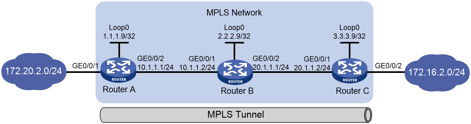
As shown in Figure 1, routers on the carrier network run MPLS. Router A and Router C are MPLS edge devices. Establish an MPLS tunnel that uses static LSPs between Router A and Router C, so that subnets 172.20.2.0/24 and 172.16.2.0/24 can access each other over MPLS.
Analysis
· To ensure the LSRs to forward packets along the correct path, make sure the outgoing label specified on an LSR is the same as the incoming label specified on the directly connected downstream LSR.
· LSPs are unidirectional. To implement bidirectional data transmission, you must configure an LSP for each direction of the data forwarding path.
· For a static LSP, only the ingress node must have a route to reach the FEC destination address. The transit and egress nodes do not need such a route. This example configures static routing on the ingress node.
Software versions used
This configuration example was created and verified on R9141P16 of the MSR2630E-X1 device.
Restrictions and guidelines
· When you configure a static route for a static LSP, make sure to specify the same outgoing interface or next hop for the static route and the static LSP.
· When configuring an ingress or transit LSR, the local public network address cannot be specified as the next hop.
· MPLS will encapsulate one or multiple label into packets. As a best practice to ensure successful packet forwarding, enable the jumboframe on MPLS-enabled interfaces and set a proper frame length according to the actual needs and the number of labels to be added.
Procedures
Table 1 Assign IP addresses to network interfaces.
Configure IP addresses and masks for interfaces as shown in Figure 1. (Details not shown.)
Table 2 Configure a static route on the ingress of each LSP to reach the FEC destination address:
# Configure Router A.
<RouterA> system-view
[RouterA] ip route-static 172.16.2.0 24 10.1.1.2
# Configure Router C.
<RouterC> system-view
[RouterC] ip route-static 172.20.2.0 24 20.1.1.1
# After the configuration is completed, execute the display ip routing-table command on the ingress to view the static route configuration. Take Router A as an example:
[RouterA] display ip routing-table
Destinations : 18 Routes : 18
Destination/Mask Proto Pre Cost NextHop Interface
0.0.0.0/32 Direct 0 0 127.0.0.1 InLoop0
1.1.1.9/32 Direct 0 0 127.0.0.1 InLoop0
10.1.1.0/24 Direct 0 0 10.1.1.1 GE0/0/2
10.1.1.0/32 Direct 0 0 10.1.1.1 GE0/0/2
10.1.1.1/32 Direct 0 0 127.0.0.1 InLoop0
10.1.1.255/32 Direct 0 0 10.1.1.1 GE0/0/2
127.0.0.0/8 Direct 0 0 127.0.0.1 InLoop0
127.0.0.0/32 Direct 0 0 127.0.0.1 InLoop0
127.0.0.1/32 Direct 0 0 127.0.0.1 InLoop0
127.255.255.255/32 Direct 0 0 127.0.0.1 InLoop0
172.16.2.0/24 Static 60 0 10.1.1.2 GE0/0/2
172.20.2.0/24 Direct 0 0 172.20.2.1 GE0/0/1
172.20.2.0/32 Direct 0 0 172.20.2.1 GE0/0/1
172.20.2.1/32 Direct 0 0 127.0.0.1 InLoop0
172.20.2.255/32 Direct 0 0 172.20.2.1 GE0/0/1
224.0.0.0/4 Direct 0 0 0.0.0.0 NULL0
224.0.0.0/24 Direct 0 0 0.0.0.0 NULL0
255.255.255.255/32 Direct 0 0 127.0.0.1 InLoop0
Table 3 Configure basic MPLS on the routers:
# Configure Router A.
[RouterA] mpls lsr-id 1.1.1.9
[RouterA] interface gigabitethernet 0/0/2
[RouterA-GigabitEthernet0/0/2] mpls enable
[RouterA-GigabitEthernet0/0/2] quit
# Configure Router B.
[RouterB] mpls lsr-id 2.2.2.9
[RouterB] interface gigabitethernet 0/0/1
[RouterB-GigabitEthernet0/0/1] mpls enable
[RouterB-GigabitEthernet0/0/1] quit
[RouterB] interface gigabitethernet 0/0/2
[RouterB-GigabitEthernet0/0/2] mpls enable
[RouterB-GigabitEthernet0/0/2] quit
# Configure Router C.
[RouterC] mpls lsr-id 3.3.3.9
[RouterC] interface gigabitethernet 0/0/1
[RouterC-GigabitEthernet0/0/1] mpls enable
[RouterC-GigabitEthernet0/0/1] quit
Table 4 Configure a static LSP from Router A to Router C:
# Configure the LSP ingress node, Router A.
[RouterA] static-lsp ingress AtoC destination 172.16.2.1 24 nexthop 10.1.1.2 out-label 30
# Configure the LSP transit node, Router B.
[RouterB] static-lsp transit AtoC in-label 30 nexthop 20.1.1.2 out-label 50
# Configure the LSP egress node, Router C.
[RouterC] static-lsp egress AtoC in-label 50
Table 5 Configure a static LSP from Router C to Router A:
# Configure the LSP ingress node, Router C.
[RouterC] static-lsp ingress CtoA destination 172.20.2.1 24 nexthop 20.1.1.1 out-label 40
# Configure the LSP transit node, Router B.
[RouterB] static-lsp transit CtoA in-label 40 nexthop 10.1.1.1 out-label 70
# Configure the LSP egress node, Router A.
[RouterA] static-lsp egress CtoA in-label 70
Verifying the configuration
# After the configuration is completed, display static LSP information on each router by using the display mpls static-lsp command. Take Router A as an example:
[RouterA] display mpls static-lsp
Total: 2
Name FEC In/Out Label Nexthop/Out Interface State
AtoC 172.16.2.0/24 NULL/30 10.1.1.2 Up
CtoA -/- 70/NULL - Up
# Test the connectivity of the static LSP from Router A to Router C.
[RouterA] ping mpls -a 172.20.2.1 ipv4 172.16.2.0 24
MPLS ping FEC 172.16.2.0/24 with 100 bytes of data:
100 bytes from 20.1.1.2: Sequence=1 time=3 ms
100 bytes from 20.1.1.2: Sequence=2 time=2 ms
100 bytes from 20.1.1.2: Sequence=3 time=2 ms
100 bytes from 20.1.1.2: Sequence=4 time=2 ms
100 bytes from 20.1.1.2: Sequence=5 time=27 ms
--- Ping statistics for FEC 172.16.2.0/24 ---
5 packets transmitted, 5 packets received, 0.0% packet loss
Round-trip min/avg/max = 2/7/27 ms
# Test the connectivity of the static LSP from Router C to Router A.
[RouterC] ping mpls -a 172.16.2.1 ipv4 172.20.2.0 24
MPLS ping FEC 172.20.2.0/24 with 100 bytes of data:
100 bytes from 10.1.1.1: Sequence=1 time=3 ms
100 bytes from 10.1.1.1: Sequence=2 time=2 ms
100 bytes from 10.1.1.1: Sequence=3 time=2 ms
100 bytes from 10.1.1.1: Sequence=4 time=2 ms
100 bytes from 10.1.1.1: Sequence=5 time=27 ms
--- Ping statistics for FEC 172.20.2.0/24 ---
5 packets transmitted, 5 packets received, 0.0% packet loss
Round-trip min/avg/max = 2/7/27 ms
Configuration files
· Router A:
#
mpls lsr-id 1.1.1.9
#
interface LoopBack0
ip address 1.1.1.9 255,255,255,255
#
interface GigabitEthernet0/0/1
port link-mode route
ip address 172.20.2.1 255.255.255.0
#
interface GigabitEthernet0/0/2
port link-mode route
ip address 10.1.1.1 255.255.255.0
mpls enable
#
ip route-static 172.16.2.0 24 10.1.1.2
#
static-lsp ingress AtoC destination 172.16.2.0 24 nexthop 10.1.1.2 out-label 30
static-lsp egress CtoA in-label 70
#
· Router B:
#
mpls lsr-id 2.2.2.9
#
interface LoopBack0
ip address 2.2.2.9 255,255,255,255
#
interface GigabitEthernet0/0/1
port link-mode route
ip address 10.1.1.2 255.255.255.0
mpls enable
#
interface GigabitEthernet0/0/2
port link-mode route
ip address 20.1.1.1 255.255.255.0
mpls enable
#
static-lsp transit AtoC in-label 30 nexthop 20.1.1.2 out-label 50
static-lsp transit CtoA in-label 40 nexthop 10.1.1.1 out-label 70
#
· Router C:
#
mpls lsr-id 3.3.3.9
#
interface LoopBack0
ip address 3.3.3.9 255,255,255,255
#
interface GigabitEthernet0/0/1
port link-mode route
ip address 20.1.1.2 255.255.255.0
mpls enable
#
interface GigabitEthernet0/0/2
port link-mode route
ip address 172.16.2.1 255.255.255.0
#
ip route-static 172.20.2.1 255.255.255.0 20.1.1.1
#
static-lsp ingress CtoA destination 172.20.2.0 24 nexthop 20.1.1.1 out-label 40
static-lsp egress AtoC in-label 50
#
Example: Configuring dynamical LSPs by using LDP
Network configuration
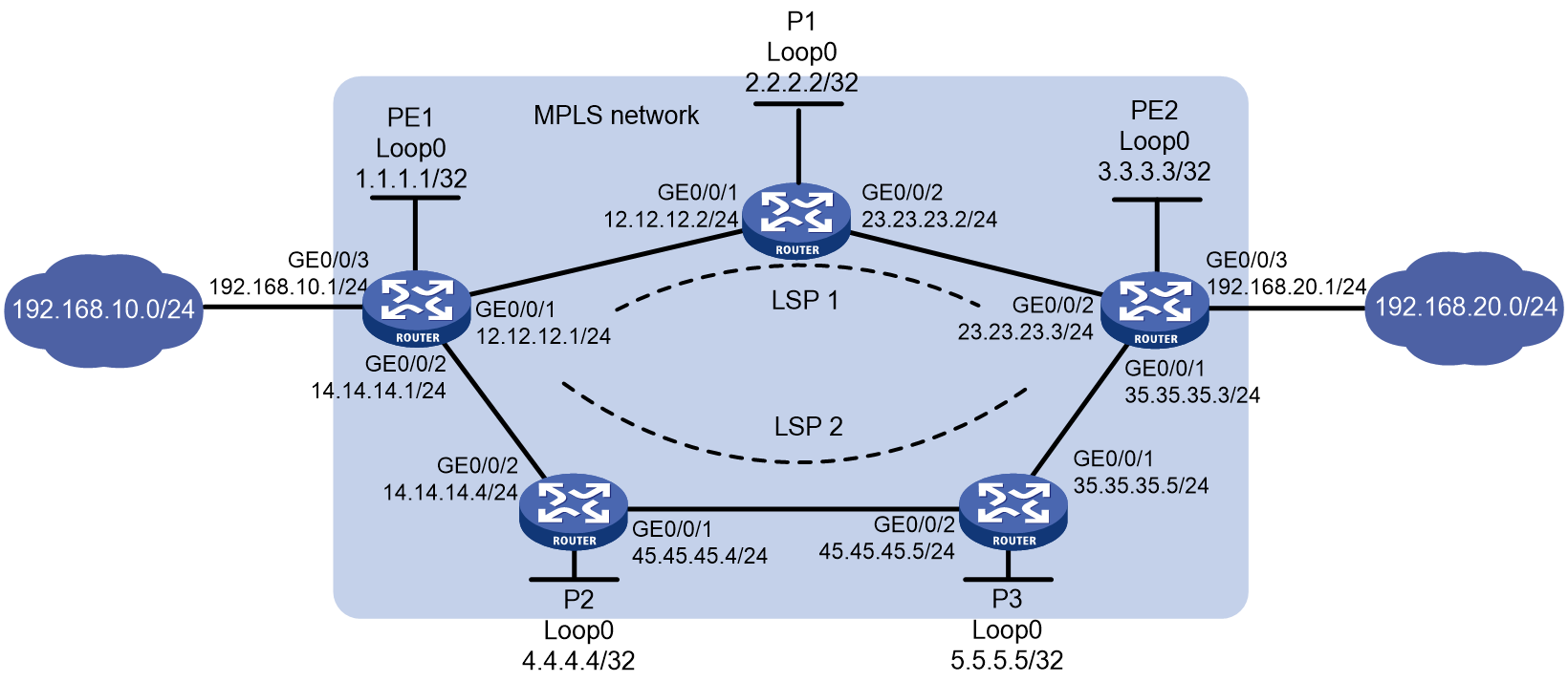
As shown in Figure 2, on the MPLS network of the carrier, PE 1 and PE 2 have two routes to each other.
· Configure LDP on the MPLS network to dynamically establish LSPs, so subnets 192.168.10.0/24 and 192.168.20.0/24 can transmit packets to each other over the LSPs.
· By default, packets are transmitted over LSP 1. When LSP 1 fails, packets are transmitted over LSP 2.
· All devices on the MPLS network allow only routes destined for 1.1.1.1/32, 2.2.2.2/32, 3.3.3.3/32, 4.4.4.4/32, 5.5.5.5/32, 192.168.10.0/24, and 192.168.20.0/24 to trigger LDP to establish LSPs. Other routes are not allowed to trigger LSP establishment to avoid affecting device performance due to excessive LSPs.
Analysis
· To create LSPs dynamically through LDP, configure a routing protocol to ensure IP connectivity between the LSRs. This example uses OSPF.
· To use LSP 1 as the primary LSP and LSP 2 as the backup LSP for packet forwarding, configure the primary route between subnet 192.168.10.0/24 and 192.168.20.0/24 as LSP 1 and the backup route as LSP 2. In this example, OSPF automatically calculates the route cost for LSP 1 to be smaller than that for LSP 2, so LSP 1 is preferred.
· To ensure that LDP establishes LSPs only for specific routes, configure LSP generation policies on each LSR.
Software versions used
This configuration example was created and verified on R9141P16 of the MSR2630E-X1 device.
Procedures
Table 1 Assign IP addresses to the network interfaces.
Configure IP addresses and masks for interfaces as shown in Figure 2. (Details not shown.)
Table 2 Configure OSPF on each router to ensure IP connectivity between them:
# Configure PE 1.
[PE1] ospf 1
[PE1-ospf-1] area 0
[PE1-ospf-1-area-0.0.0.0] network 1.1.1.1 0.0.0.0
[PE1-ospf-1-area-0.0.0.0] network 12.12.12.0 0.0.0.255
[PE1-ospf-1-area-0.0.0.0] network 14.14.14.0 0.0.0.255
[PE1-ospf-1-area-0.0.0.0] network 192.168.10.0 0.0.0.255
[PE1-ospf-1-area-0.0.0.0] quit
[PE1-ospf-1] quit
# Configure P 1.
[P1] ospf 1
[P1-ospf-1] area 0
[P1-ospf-1-area-0.0.0.0] network 2.2.2.2 0.0.0.0
[P1-ospf-1-area-0.0.0.0] network 12.12.12.0 0.0.0.255
[P1-ospf-1-area-0.0.0.0] network 23.23.23.0 0.0.0.255
[P1-ospf-1-area-0.0.0.0] quit
[P1-ospf-1] quit
# Configure P 2.
[P2] ospf 1
[P2-ospf-1] area 0
[P2-ospf-1-area-0.0.0.0] network 4.4.4.4 0.0.0.0
[P2-ospf-1-area-0.0.0.0] network 14.14.14.0 0.0.0.255
[P2-ospf-1-area-0.0.0.0] network 45.45.45.0 0.0.0.255
[P2-ospf-1-area-0.0.0.0] quit
[P2-ospf-1] quit
# Configure P 3.
[P3] ospf 1
[P3-ospf-1] area 0
[P3-ospf-1-area-0.0.0.0] network 5.5.5.5 0.0.0.0
[P3-ospf-1-area-0.0.0.0] network 45.45.45.0 0.0.0.255
[P3-ospf-1-area-0.0.0.0] network 35.35.35.0 0.0.0.255
[P3-ospf-1-area-0.0.0.0] quit
[P3-ospf-1] quit
# Configure PE 2.
[PE2] ospf 1
[PE2-ospf-1] area 0
[PE2-ospf-1-area-0.0.0.0] network 3.3.3.3 0.0.0.0
[PE2-ospf-1-area-0.0.0.0] network 23.23.23.0 0.0.0.255
[PE2-ospf-1-area-0.0.0.0] network 35.35.35.0 0.0.0.255
[PE2-ospf-1-area-0.0.0.0] network 192.168.20.0 0.0.0.255
[PE2-ospf-1-area-0.0.0.0] quit
[PE2-ospf-1] quit
# After the configuration is completed, execute the display ospf routing command on each router to verify that the routers have learned the routes to each other. Use PE1 as an example:
[PE1] display ospf routing
OSPF Process 1 with Router ID 1.1.1.1
Routing Table
Routing for network
Destination Cost Type NextHop AdvRouter Area
45.45.45.0/24 2 Transit 14.14.14.4 5.5.5.5 0.0.0.0
35.35.35.0/24 3 Transit 14.14.14.4 5.5.5.5 0.0.0.0
35.35.35.0/24 3 Transit 12.12.12.2 5.5.5.5 0.0.0.0
192.168.10.0/24 1 Stub 192.168.10.1 1.1.1.1 0.0.0.0
5.5.5.5/32 2 Stub 14.14.14.4 5.5.5.5 0.0.0.0
14.14.14.0/24 1 Transit 14.14.14.1 4.4.4.4 0.0.0.0
23.23.23.0/24 2 Transit 12.12.12.2 3.3.3.3 0.0.0.0
4.4.4.4/32 1 Stub 14.14.14.4 4.4.4.4 0.0.0.0
3.3.3.3/32 2 Stub 12.12.12.2 3.3.3.3 0.0.0.0
12.12.12.0/24 1 Transit 12.12.12.1 2.2.2.2 0.0.0.0
2.2.2.2/32 1 Stub 12.12.12.2 2.2.2.2 0.0.0.0
1.1.1.1/32 0 Stub 1.1.1.1 1.1.1.1 0.0.0.0
192.168.20.0/24 3 Stub 12.12.12.2 3.3.3.3 0.0.0.0
Total nets: 13
Intra area: 13 Inter area: 0 ASE: 0 NSSA: 0
PE 1 should have established OSPF peering with P 1 and P 2, and PE 2 with P 2 and P 3. Execute the display ospf peer verbose command to verify that the OSPF neighbors are in Full state. Use PE1 as an example:
[PE1] display ospf peer verbose
OSPF Process 1 with Router ID 1.1.1.1
Neighbors
Area 0.0.0.0 interface 14.14.14.1(GigabitEthernet0/0/2)'s neighbors
Router ID: 4.4.4.4 Address: 14.14.14.4 GR state: Normal
State: Full Mode: Nbr is master Priority: 1
DR: 14.14.14.4 BDR: 14.14.14.1 MTU: 0
Options is 0x42 (-|O|-|-|-|-|E|-)
Dead timer due in 40 sec
Neighbor is up for 00:03:30
Authentication Sequence: [ 0 ]
Neighbor state change count: 6
BFD status: Disabled
Neighbors
Area 0.0.0.0 interface 12.12.12.1(GigabitEthernet0/0/1)'s neighbors
Router ID: 2.2.2.2 Address: 12.12.12.2 GR state: Normal
State: Full Mode: Nbr is master Priority: 1
DR: 12.12.12.2 BDR: 12.12.12.1 MTU: 0
Options is 0x42 (-|O|-|-|-|-|E|-)
Dead timer due in 36 sec
Neighbor is up for 00:03:24
Authentication Sequence: [ 0 ]
Neighbor state change count: 6
BFD status: Disabled
Table 3 Enable basic MPLS and MPLS LDP:
# Configure PE 1.
[PE1] mpls lsr-id 1.1.1.1
[PE1] mpls ldp
[PE1-ldp] quit
[PE1] interface gigabitethernet 0/0/1
[PE1-GigabitEthernet0/0/1] mpls enable
[PE1-GigabitEthernet0/0/1] mpls ldp enable
[PE1-GigabitEthernet0/0/1] quit
[PE1] interface gigabitethernet 0/0/2
[PE1-GigabitEthernet0/0/2] mpls enable
[PE1-GigabitEthernet0/0/2] mpls ldp enable
[PE1-GigabitEthernet0/0/2] quit
# Configure P 1.
[P1] mpls lsr-id 2.2.2.2
[P1] mpls ldp
[P1-ldp] quit
[P1] interface gigabitethernet 0/0/1
[P1-GigabitEthernet0/0/1] mpls enable
[P1-GigabitEthernet0/0/1] mpls ldp enable
[P1-GigabitEthernet0/0/1] quit
[P1] interface gigabitethernet 0/0/2
[P1-GigabitEthernet0/0/2] mpls enable
[P1-GigabitEthernet0/0/2] mpls ldp enable
[P1-GigabitEthernet0/0/2] quit
# Configure P 2.
[P2] mpls lsr-id 4.4.4.4
[P2] mpls ldp
[P2-ldp] quit
[P2] interface gigabitethernet 0/0/1
[P2-GigabitEthernet0/0/1] mpls enable
[P2-GigabitEthernet0/0/1] mpls ldp enable
[P2-GigabitEthernet0/0/1] quit
[P2] interface gigabitethernet 0/0/2
[P2-GigabitEthernet0/0/2] mpls enable
[P2-GigabitEthernet0/0/2] mpls ldp enable
[P2-GigabitEthernet0/0/2] quit
# Configure P 3.
[P3] mpls lsr-id 5.5.5.5
[P3] mpls ldp
[P3-ldp] quit
[P3] interface gigabitethernet 0/0/1
[P3-GigabitEthernet0/0/1] mpls enable
[P3-GigabitEthernet0/0/1] mpls ldp enable
[P3-GigabitEthernet0/0/1] quit
[P3] interface gigabitethernet 0/0/2
[P3-GigabitEthernet0/0/2] mpls enable
[P3-GigabitEthernet0/0/2] mpls ldp enable
[P3-GigabitEthernet0/0/2] quit
# Configure PE 2.
[PE2] mpls lsr-id 3.3.3.3
[PE2] mpls ldp
[PE2-ldp] quit
[PE2] interface gigabitethernet 0/0/1
[PE2-GigabitEthernet0/0/1] mpls enable
[PE2-GigabitEthernet0/0/1] mpls ldp enable
[PE2-GigabitEthernet0/0/1] quit
[PE2] interface gigabitethernet 0/0/2
[PE2-GigabitEthernet0/0/2] mpls enable
[PE2-GigabitEthernet0/0/2] mpls ldp enable
[PE2-GigabitEthernet0/0/2] quit
After the configuration is completed, PE 1 should have established local LDP sessions with P 1 and P 2, and PE 2 with P 2 and P 3.
Execute the display mpls ldp peer command on each router to view the LDP peer information. Use PE1 as an example:
[PE1] display mpls ldp peer
Total number of peers: 2
Peer LDP ID State Role GR MD5 KA Sent/Rcvd
2.2.2.2:0 Operational Passive Off Off 55/55
4.4.4.4:0 Operational Passive Off Off 6/6
Table 4 Configure an LSP generation policy to establish LSPs for routes destined for 1.1.1.1/32, 2.2.2.2/32, 3.3.3.3/32, 4.4.4.4/32, 5.5.5.5/32, 192.168.10.0/24, and 192.168.20.0/24:
# On PE 1, configure IP prefix list PE1, and configure LDP to use only the routes permitted by the prefix list to establish LSPs.
[PE1] ip prefix-list PE1 index 10 permit 1.1.1.1 32
[PE1] ip prefix-list PE1 index 20 permit 2.2.2.2 32
[PE1] ip prefix-list PE1 index 30 permit 3.3.3.3 32
[PE1] ip prefix-list PE1 index 40 permit 4.4.4.4 32
[PE1] ip prefix-list PE1 index 50 permit 5.5.5.5 32
[PE1] ip prefix-list PE1 index 60 permit 192.168.10.0 24
[PE1] ip prefix-list PE1 index 70 permit 192.168.20.0 24
[PE1] mpls ldp
[PE1-ldp] lsp-trigger prefix-list PE1
[PE1-ldp] quit
# On P 1, configure IP prefix list P1, and configure LDP to use only the routes permitted by the prefix list to establish LSPs.
[P1] ip prefix-list P1 index 10 permit 1.1.1.1 32
[P1] ip prefix-list P1 index 20 permit 2.2.2.2 32
[P1] ip prefix-list P1 index 30 permit 3.3.3.3 32
[P1] ip prefix-list P1 index 40 permit 4.4.4.4 32
[P1] ip prefix-list P1 index 50 permit 5.5.5.5 32
[P1] ip prefix-list P1 index 60 permit 192.168.10.0 24
[P1] ip prefix-list P1 index 70 permit 192.168.20.0 24
[P1] mpls ldp
[P1-ldp] lsp-trigger prefix-list P1
[P1-ldp] quit
# On P 2, configure IP prefix list P2, and configure LDP to use only the routes permitted by the prefix list to establish LSPs.
[P2] ip prefix-list P2 index 10 permit 1.1.1.1 32
[P2] ip prefix-list P2 index 20 permit 2.2.2.2 32
[P2] ip prefix-list P2 index 30 permit 3.3.3.3 32
[P2] ip prefix-list P2 index 40 permit 4.4.4.4 32
[P2] ip prefix-list P2 index 50 permit 5.5.5.5 32
[P2] ip prefix-list P2 index 60 permit 192.168.10.0 24
[P2] ip prefix-list P2 index 70 permit 192.168.20.0 24
[P2] mpls ldp
[P2-ldp] lsp-trigger prefix-list P2
[P2-ldp] quit
# On P 3, configure IP prefix list P3, and configure LDP to use only the routes permitted by the prefix list to establish LSPs.
[P3] ip prefix-list P3 index 10 permit 1.1.1.1 32
[P3] ip prefix-list P3 index 20 permit 2.2.2.2 32
[P3] ip prefix-list P3 index 30 permit 3.3.3.3 32
[P3] ip prefix-list P3 index 40 permit 4.4.4.4 32
[P3] ip prefix-list P3 index 50 permit 5.5.5.5 32
[P3] ip prefix-list P3 index 60 permit 192.168.10.0 24
[P3] ip prefix-list P3 index 70 permit 192.168.20.0 24
[P3] mpls ldp
[P3-ldp] lsp-trigger prefix-list P3
[P3-ldp] quit
# On PE 2, configure IP prefix list PE 2, and configure LDP to use only the routes permitted by the prefix list to establish LSPs.
[PE2] ip prefix-list PE2 index 10 permit 1.1.1.1 32
[PE2] ip prefix-list PE2 index 20 permit 2.2.2.2 32
[PE2] ip prefix-list PE2 index 30 permit 3.3.3.3 32
[PE2] ip prefix-list PE2 index 40 permit 4.4.4.4 32
[PE2] ip prefix-list PE2 index 50 permit 5.5.5.5 32
[PE2] ip prefix-list PE2 index 60 permit 192.168.10.0 24
[PE2] ip prefix-list PE2 index 70 permit 192.168.20.0 24
[PE2] mpls ldp
[PE2-ldp] lsp-trigger prefix-list PE2
[PE2-ldp] quit
Verifying the configuration
After the configuration is completed, execute the display mpls ldp lsp command on PE 1 to view LDP LSP information. The output shows that the LSP destined for subnet 192.168.20.0/24 uses P 1 as the next hop by default.
[PE1] display mpls ldp lsp
Status Flags: * - stale, L - liberal, B - backup
FECs: 7 Ingress LSPs: 5 Transit LSPs: 5 Egress LSPs: 2
FEC In/Out Label Nexthop OutInterface
1.1.1.1/32 3/-
-/1151(L)
-/1151(L)
2.2.2.2/32 -/3 12.12.12.2 GE0/0/1
1151/3 12.12.12.2 GE0/0/1
-/1150(L)
3.3.3.3/32 -/1150 12.12.12.2 GE0/0/1
1150/1150 12.12.12.2 GE0/0/1
-/1148(L)
4.4.4.4/32 -/1149(L)
-/3 14.14.14.4 GE0/0/2
1149/3 14.14.14.4 GE0/0/2
5.5.5.5/32 -/1148(L)
-/1149 14.14.14.4 GE0/0/2
1148/1149 14.14.14.4 GE0/0/2
192.168.10.0/24 1145/-
-/1146(L)
-/1146(L)
192.168.20.0/24 -/1147 12.12.12.2 GE0/0/1
1146/1147 12.12.12.2 GE0/0/1
-/1147(L)
# Perform MPLS ping to test the validity and reachability of an MPLS LSP.
[PE1] ping mpls -a 192.168.10.1 ipv4 192.168.20.0 24
MPLS ping FEC 192.168.20.0/24 with 100 bytes of data:
100 bytes from 23.23.23.3: Sequence=1 time=2 ms
100 bytes from 23.23.23.3: Sequence=2 time=2 ms
100 bytes from 23.23.23.3: Sequence=3 time=2 ms
100 bytes from 23.23.23.3: Sequence=4 time=2 ms
100 bytes from 23.23.23.3: Sequence=5 time=2 ms
--- Ping statistics for FEC 192.168.20.0/24 ---
5 packets transmitted, 5 packets received, 0.0% packet loss
Round-trip min/avg/max = 2/2/2 ms
# When P 1 fails, execute the display mpls ldp lsp command. The output shows that the LSP destined for subnet 192.168.20.0/24 uses P 2 as the next hop.
[PE1] display mpls ldp lsp
Status Flags: * - stale, L - liberal, B - backup
FECs: 7 Ingress LSPs: 5 Transit LSPs: 5 Egress LSPs: 2
FEC In/Out Label Nexthop OutInterface
1.1.1.1/32 3/-
-/1150(L)
2.2.2.2/32 -/1149 14.14.14.4 GE0/0/2
1150/1149 14.14.14.4 GE0/0/2
3.3.3.3/32 -/1148 14.14.14.4 GE0/0/2
1147/1148 14.14.14.4 GE0/0/2
4.4.4.4/32 -/3 14.14.14.4 GE0/0/2
1149/3 14.14.14.4 GE0/0/2
5.5.5.5/32 -/1151 14.14.14.4 GE0/0/2
1148/1151 14.14.14.4 GE0/0/2
192.168.10.0/24 1151/-
-/1146(L)
-/1146(L)
192.168.20.0/24 -/1147 14.14.14.4 GE0/0/2
1146/1147 14.14.14.4 GE0/0/2
# Perform MPLS ping to test the validity and reachability of an MPLS LSP.
[PE1] ping mpls -a 192.168.10.1 ipv4 192.168.20.0 24
MPLS ping FEC 192.168.20.0/24 with 100 bytes of data:
100 bytes from 35.35.35.3: Sequence=1 time=1 ms
100 bytes from 35.35.35.3: Sequence=2 time=1 ms
100 bytes from 35.35.35.3: Sequence=3 time=1 ms
100 bytes from 35.35.35.3: Sequence=4 time=1 ms
100 bytes from 35.35.35.3: Sequence=5 time=1 ms
--- Ping statistics for FEC 192.168.20.0/24 ---
5 packets transmitted, 5 packets received, 0.0% packet loss
Round-trip min/avg/max = 1/1/1 ms
Configuration files
· PE 1:
#
ospf 1
area 0.0.0.0
network 1.1.1.1 0.0.0.0
network 12.12.12.0 0.0.0.255
network 14.14.14.0 0.0.0.255
network 192.168.10.0 0.0.0.255
#
mpls lsr-id 1.1.1.1
#
mpls ldp
lsp-trigger prefix-list PE1
#
interface LoopBack0
ip address 1.1.1.1 255,255,255,255
#
interface GigabitEthernet0/0/1
port link-mode route
ip address 12.12.12.1 255.255.255.0
mpls enable
mpls ldp enable
#
interface GigabitEthernet0/0/2
port link-mode route
ip address 14.14.14.1 255.255.255.0
mpls enable
mpls ldp enable
#
interface GigabitEthernet0/0/3
port link-mode route
ip address 192.168.10.1 255.255.255.0
#
ip prefix-list PE1 index 10 permit 1.1.1.1 32
ip prefix-list PE1 index 20 permit 2.2.2.2 32
ip prefix-list PE1 index 30 permit 3.3.3.3 32
ip prefix-list PE1 index 40 permit 4.4.4.4 32
ip prefix-list PE1 index 50 permit 5.5.5.5 32
ip prefix-list PE1 index 60 permit 192.168.10.0 24
ip prefix-list PE1 index 70 permit 192.168.20.0 24
· P 1:
#
ospf 1
area 0.0.0.0
network 2.2.2.2 0.0.0.0
network 12.12.12.0 0.0.0.255
network 23.23.23.0 0.0.0.255
#
mpls lsr-id 2.2.2.2
#
mpls ldp
lsp-trigger prefix-list P1
#
interface LoopBack0
ip address 2.2.2.2 255,255,255,255
#
interface GigabitEthernet0/0/1
port link-mode route
ip address 12.12.12.2 255.255.255.0
mpls enable
mpls ldp enable
#
interface GigabitEthernet0/0/2
port link-mode route
ip address 23.23.23.2 255.255.255.0
mpls enable
mpls ldp enable
#
ip prefix-list P1 index 10 permit 1.1.1.1 32
ip prefix-list P1 index 20 permit 2.2.2.2 32
ip prefix-list P1 index 30 permit 3.3.3.3 32
ip prefix-list P1 index 40 permit 4.4.4.4 32
ip prefix-list P1 index 50 permit 5.5.5.5 32
ip prefix-list P1 index 60 permit 192.168.10.0 24
ip prefix-list P1 index 70 permit 192.168.20.0 24
#
· P 2:
#
ospf 1
area 0.0.0.0
network 4.4.4.4 0.0.0.0
network 14.14.14.0 0.0.0.255
network 45.45.45.0 0.0.0.255
#
mpls lsr-id 4.4.4.4
#
mpls ldp
lsp-trigger prefix-list P2
#
interface LoopBack0
ip address 4.4.4.4 255,255,255,255
#
interface GigabitEthernet0/0/1
port link-mode route
ip address 45.45.45.4 255.255.255.0
mpls enable
mpls ldp enable
#
interface GigabitEthernet0/0/2
port link-mode route
ip address 14.14.14.4 255.255.255.0
mpls enable
mpls ldp enable
#
ip prefix-list P2 index 10 permit 1.1.1.1 32
ip prefix-list P2 index 20 permit 2.2.2.2 32
ip prefix-list P2 index 30 permit 3.3.3.3 32
ip prefix-list P2 index 40 permit 4.4.4.4 32
ip prefix-list P2 index 50 permit 5.5.5.5 32
ip prefix-list P2 index 60 permit 192.168.10.0 24
ip prefix-list P2 index 70 permit 192.168.20.0 24
#
· P 3:
#
ospf 1
area 0.0.0.0
network 5.5.5.5 0.0.0.0
network 35.35.35.0 0.0.0.255
network 45.45.45.0 0.0.0.255
#
mpls lsr-id 5.5.5.5
#
mpls ldp
lsp-trigger prefix-list P3
#
interface LoopBack0
ip address 2.2.2.2 255,255,255,255
#
interface GigabitEthernet0/0/1
port link-mode route
ip address 35.35.35.5 255.255.255.0
mpls enable
mpls ldp enable
#
interface GigabitEthernet0/0/1
port link-mode route
ip address 45.45.45.5 255.255.255.0
mpls enable
mpls ldp enable
#
ip prefix-list P3 index 10 permit 1.1.1.1 32
ip prefix-list P3 index 20 permit 2.2.2.2 32
ip prefix-list P3 index 30 permit 3.3.3.3 32
ip prefix-list P3 index 40 permit 4.4.4.4 32
ip prefix-list P3 index 50 permit 5.5.5.5 32
ip prefix-list P3 index 60 permit 192.168.10.0 24
ip prefix-list P3 index 70 permit 192.168.20.0 24
#
· PE 2:
#
ospf 1
area 0.0.0.0
network 3.3.3.3 0.0.0.0
network 23.23.23.0 0.0.0.255
network 33.0.0.0 0.0.0.255
network 192.168.20.0 0.0.0.255
#
mpls lsr-id 3.3.3.3
#
mpls ldp
lsp-trigger prefix-list PE2
#
interface LoopBack0
ip address 3.3.3.3 255,255,255,255
#
interface GigabitEthernet0/0/1
port link-mode route
ip address 35.35.35.3 255.255.255.0
mpls enable
mpls ldp enable
#
interface GigabitEthernet0/0/2
port link-mode route
ip address 23.23.23.3 255.255.255.0
mpls enable
mpls ldp enable
#
interface GigabitEthernet0/0/3
port link-mode route
ip address 192.168.20.1 255.255.255.0
#
ip prefix-list PE2 index 10 permit 1.1.1.1 32
ip prefix-list PE2 index 20 permit 2.2.2.2 32
ip prefix-list PE2 index 30 permit 3.3.3.3 32
ip prefix-list PE2 index 40 permit 4.4.4.4 32
ip prefix-list PE2 index 50 permit 5.5.5.5 32
ip prefix-list PE2 index 60 permit 192.168.10.0 24
ip prefix-list PE2 index 70 permit 192.168.20.0 24
#
Related documentation
· MPLS Configuration Guide in H3C MSR1000[2600][3600] Routers Configuration Guides (V9)
· MPLS Command Reference in H3C MSR1000[2600][3600] Routers Command References (V9)