- Table of Contents
-
- H3C MSR1000[2600][3600] Routers Configuration Examples All-in-One-R9141-6W100
- 00-Preface
- 01-Local 802.1X Authentication Configuration Examples
- 02-RADIUS-Based 802.1X Authentication Configuration Examples
- 03-AAA Configuration Examples
- 04-ACL Configuration Examples
- 05-MPLS over ADVPN Configuration Examples
- 06-ARP Attack Protection Configuration Examples
- 07-BFD Configuration Examples
- 08-Basic BGP Configuration Examples
- 09-BGP Route Attribute-Based Route Selection Configuration Examples
- 10-EAA Monitor Policy Configuration Examples
- 11-GRE with OSPF Configuration Examples
- 12-HoVPN Configuration Examples
- 13-IGMP Snooping Configuration Examples
- 14-IGMP Configuration Examples
- 15-IPsec Configuration Examples
- 16-IPsec Digital Certificate Authentication Configuration Examples
- 17-IPv6 IS-IS Configuration Examples
- 18-IPv6 over IPv4 GRE Tunnel Configuration Examples
- 19-IPv6 over IPv4 Manual Tunnel with OSPFv3 Configuration Examples
- 20-IS-IS Configuration Examples
- 21-Combined ISATAP Tunnel and 6to4 Tunnel Configuration Examples
- 22-L2TP over IPsec Configuration Examples
- 23-Multi-Instance L2TP Configuration Examples
- 24-L2TP Multidomain Access Configuration Examples
- 25-MPLS L3VPN Configuration Examples
- 26-MPLS OAM Configuration Examples
- 27-MPLS TE Configuration Examples
- 28-Basic MPLS Configuration Examples
- 29-NAT DNS Mapping Configuration Examples
- 30-NetStream Configuration Examples
- 31-NQA Configuration Examples
- 32-NTP Configuration Examples
- 33-OSPFv3 Configuration Examples
- 34-OSPF Configuration Examples
- 35-OSPF Multi-Process Configuration Examples
- 36-OSPF Multi-Instance Configuration Examples
- 37-Portal Configuration Examples
- 38-PPP Configuration Examples
- 39-RBAC Configuration Examples
- 40-RMON Configuration Examples
- 41-IPv4 NetStream Sampling Configuration Examples
- 42-SNMP Configuration Examples
- 43-SRv6 Configuration Examples
- 44-SSH Configuration Examples
- 45-Tcl Commands Configuration Examples
- 46-VLAN Configuration Examples
- 47-VRRP Configuration Examples
- 48-VXLAN over IPsec Configuration Examples
- 49-WLAN AC Configuration Examples
- 50-Small and Medium-Sized Store Configuration Examples
- 51-Cloudnet VPN Configuration Examples
- 52-Ethernet Link Aggregation Configuration Examples
- 53-Ethernet OAM Configuration Examples
- 54-Outbound Bidirectional NAT Configuration Examples
- 55-NAT Hairpin in C-S Mode Configuration Examples
- 56-Load Sharing NAT Server Configuration Examples
- 57-BIDIR-PIM Configuration Examples
- 58-Control Plane-Based QoS Policy Configuration Examples
- 59-Scheduling a Task Configuration Examples
- 60-Client-Initiated L2TP Tunnel Configuration Examples
- 61-LAC-Auto-Initiated L2TP Tunnel Configuration Examples
- 62-Authorized ARP Configuration Examples
- 63-GTS Configuration Examples
- 64-Traffic Policing Configuration Examples
- 65-Traffic Accounting Configuration Examples
- 66-Mobile Communication Modem Management Configuration Examples
- 67-Port Isolation Configuration Examples
- 68-PBR Configuration Examples
- 69-TFTP Client Software Upgrade Configuration Examples
- 70-FTP Client Software Upgrade Configuration Examples
- 71-FTP Server Software Upgrade Configuration Examples
- 72-Routing Policy Configuration Examples
- 73-Software Upgrade from the BootWare Menu Configuration Examples
- 74-Mirroring Configuration Examples
- Related Documents
-
| Title | Size | Download |
|---|---|---|
| 51-Cloudnet VPN Configuration Examples | 950.87 KB |
H3C Routers
Cloudnet VPN Configuration Examples
Copyright © 2024 New H3C Technologies Co., Ltd. All rights reserved.
No part of this manual may be reproduced or transmitted in any form or by any means without prior written consent of Hangzhou H3C Technologies Co., Ltd.
Except for the trademarks of New H3C Technologies Co., Ltd., any trademarks that may be mentioned in this document are the property of their respective owners.
The information in this document is subject to change without notice.
Contents
Example: Configuring Cloudnet VPN
Log in to the Cloudnet platform
(Optional) Configuring VPN configuration
(Optional) Subscribing to tunnel state alarms
Introduction
This document describes typical configurations for Cloudnet VPN.
The Cloudnet platform is a new IT online operating platform established to meet Internet+ requirements. The Cloudnet VPN solution relies on the Cloudnet platform and uses the Hub-Spoke method to establish dedicated VPN tunnels.
Prerequisites
The configuration examples were created and verified in a lab environment, and all the devices were started with the factory default configuration. When you are working on a live network, make sure you understand the potential impact of every command on your network.
This assumes that you have basic knowledge of IPsec.
Restrictions and guidelines
The method of creating branch VPNs in bulk is only applicable to devices of the same model. The method is suitable only for scenarios where multiple sites use devices of the same model.
Example: Configuring Cloudnet VPN
Network configuration
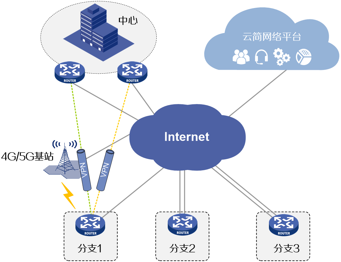
Branches connect to the center using a Hub-Spoke topology, where the center functions as the Hub site and each branch functions as a Spoke site. Branch 1 connects to the center using a wired link and a 4G/5G backup link, and Branches 2 and 3 use two wired links for access. Create Cloudnet VPN tunnels between the center and branches based on actual service requirements. Use the Cloudnet platform to ensure online service security between the center and the branches. For example, to establish Cloudnet VPN tunnels between the center and branch 1:
· Establish two VPN tunnels between the center and branch 1.
· Configure the two tunnels to operate in master/backup state. When the master tunnel disconnects, configure the backup tunnel to take over services.
Figure 1 Network diagram
Analysis
Table 1 Create two center VPNs on the center and configure the priorities for the two VPN domains. Adjust the VPN domain priorities to establish a master-backup relationship.
Table 2 Create two branch VPNs on branch 1. Configure the egress interface and VPN domain for each branch VPN, for the two VPN tunnels established between branch 1 and the center to back up each other.
Software versions used
This configuration example was created and verified on Cloudnet R202404 and R9141P16 of the MSR2630E-X1 router.
Restrictions and guidelines
· To establish Cloudnet VPN tunnels, specify the same VPN domain for the center VPNs and branch VPNs.
· For a VPN domain to be available on branch VPNs, you must first configure the domain on the center VPNs.
· The smaller the VPN domain priority value, the higher the priority of the VPN domain.
Procedures
Log in to the Cloudnet platform
Table 1 Open a browser, and enter https://oasis.h3c.com/ in the address bar to access the Cloudnet interface. As shown in Figure 2, enter the username and password of your Cloudnet account and click to log in to Cloudnet. This configuration uses username admin as an example.
Figure 2 H3C Cloudnet interface
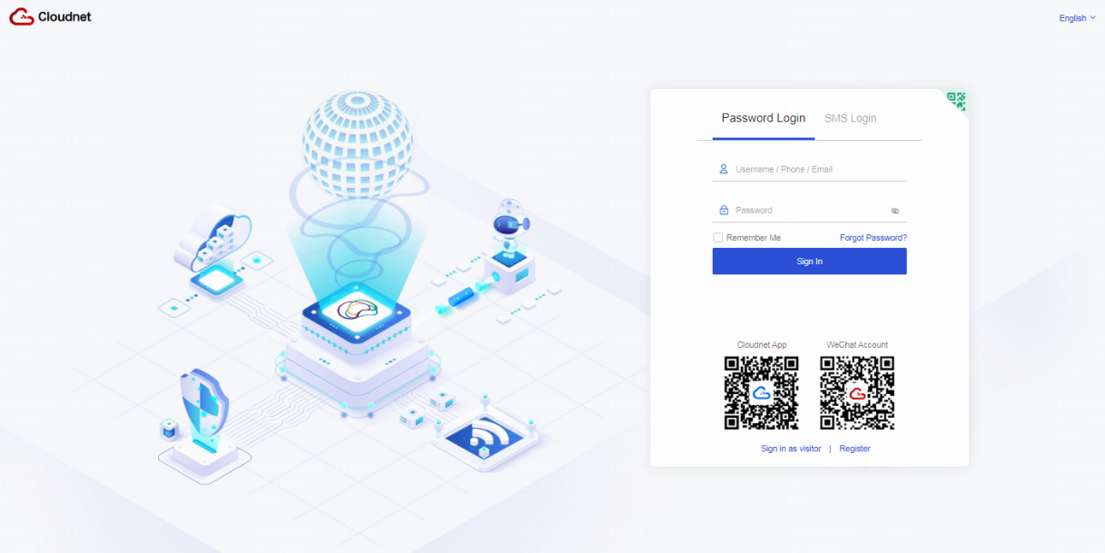
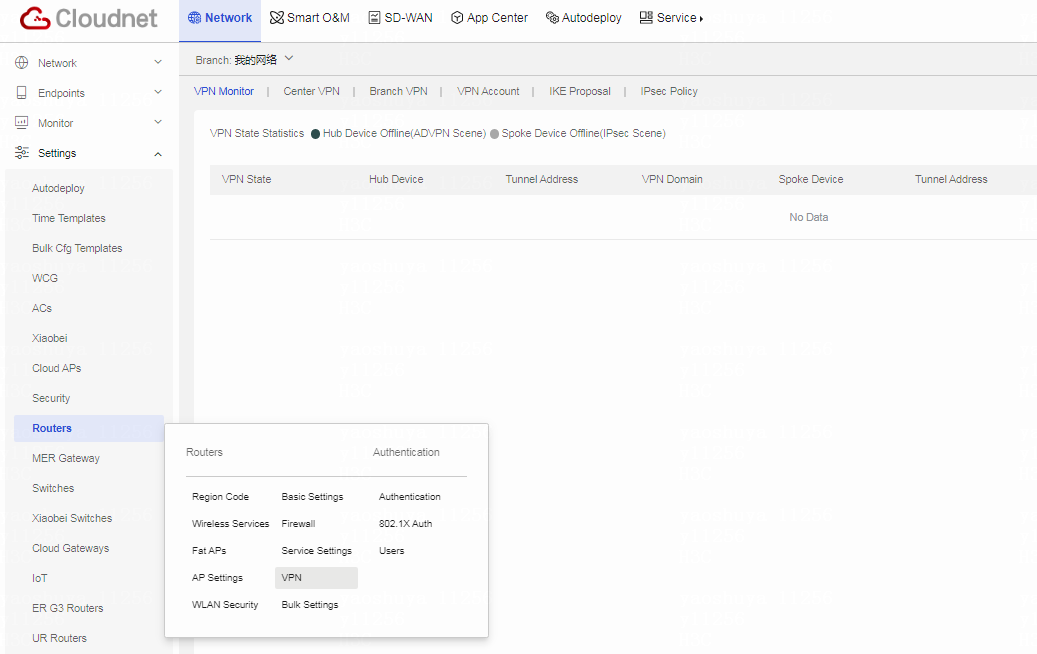
Table 2 Click Network on the top navigation bar, and then select Settings > Routers > VPN from the left navigation pane.
Figure 3 Cloudnet VPN configuration page
Creating center VPNs
Creating center VPN 1
Table 1 Click the Center VPN tab. Click Add (ADVPN Scene).

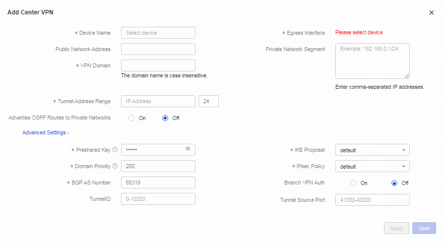
Table 2 Configure center VPN parameters. Parameters marked with a red asterisk (*) are required.
Configure center VPN1 as follows:
a. Select the center device from the Device Name field.
b. Select the egress interface.
c. Specify the VPN domain name for the center VPN in the VPN Domain field.
d. Specify the tunnel address.
e. Enter the preshared key.
f. Enter the priority of the VPN domain. Smaller the value, higher the priority.
g. Use the default settings in the BGP AS Number, IKE Proposal, IPsec Policy, TunnelID, Tunnel Source Port, and Branch VPN Auth fields.
h. Click Apply.
Figure 5 Configuring advanced settings for the center VPN
After the configuration and application, the center VPN page displays the application status of center VPN 1.
Creating center VPN 2
Create center VPN 2 in the same way center VPN 1 was created.
Creating branch VPNs
Creating branch VPN 1
Table 1 Click the Branch VPN tab. Click Add (ADVPN Scene).
Figure 6 Creating a branch VPN for the ADVPN scene
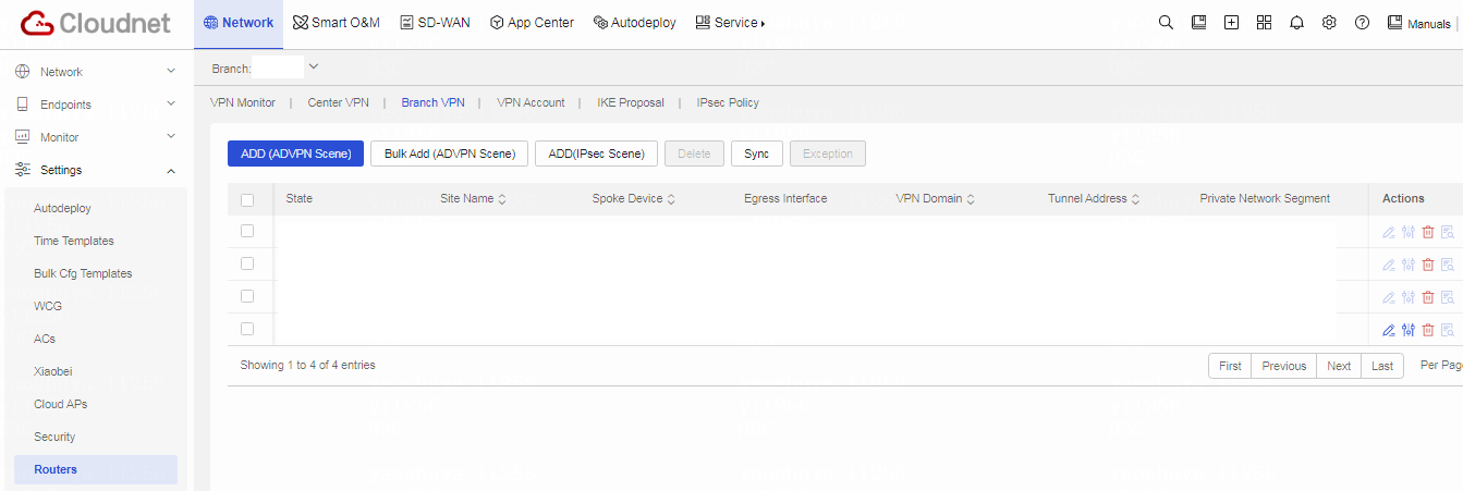
Table 2 Configure branch VPN parameters.
Configure branch VPN 1 as follows:
a. Select the branch device from the Device Name field.
b. Select the egress interface of the branch device.
c. Select the VPN domain configured for the center VPN.
d. Select the private network interfaces of the branch device.
e. Select the traffic forwarding mode. If you select local forwarding, the branch forwards only the VPN traffic to the center VPN. If you select centralized forwarding, the branch forwards all traffic to the center VPN.
f. Retain the default settings for advanced configuration fields.
g. Click Apply.
Figure 7 Creating branch VPN 1

After the configuration and application, the branch VPN page displays the application status of branch VPN 1.
Creating branch VPN 2
Create branch VPN 2 in the same way branch VPN 1 was created.
Creating branch VPNs in bulk
|
|
NOTE: Use this method to create branch VPNs in bulk for devices of the same model. In this method, you must first select the target sites after clicking the Bulk Add button. Each site has a router by default, and selecting a site is equivalent to selecting the corresponding router. |
Table 1 Click the Branch VPN tab. Click Bulk Add (ADVPN Scene). Select the target sites and then click Next.
Figure 8 Creating branch VPNs in bulk
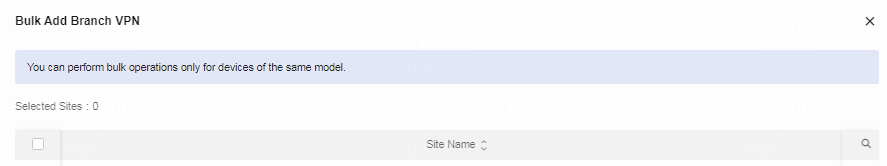
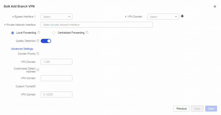
Table 2 Configure branch VPN parameters. Parameters marked with a red asterisk (*) are required.
Configure branch VPNs as follows:
a. Select the egress interface of the branch device.
b. Select the VPN domain configured for the center VPN.
c. Select the private network interfaces of the branch device.
d. Select the traffic forwarding mode. If you select local forwarding, the branch forwards only the VPN traffic to the center VPN. If you select centralized forwarding, the branch forwards all traffic to the center VPN.
e. Retain the default settings for advanced configuration fields.
f. Click Apply.
Figure 9 Creating branch VPNs in bulk
(Optional) Configuring VPN configuration
(Optional) Configuring a VPN account
Table 1 On the VPN page, click the VPN Account tab.
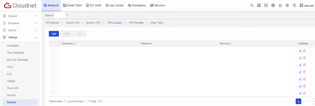
Table 2 Click Add. Configure a VPN account as follows:
a. Specify the VPN account name.
b. Set the VPN account password.
c. Enter the VPN account password again in the Confirm Password field.
d. Specify the remarks as needed.
e. Click OK.
Figure 11 Adding a VPN account
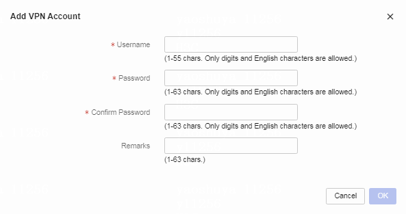
Table 3 On the VPN Account tab, select the target VPN accounts, and then click Sync to synchronize the accounts to the center device.
Table 4 In the dialog box that opens, select the target sites and then click OK.
Figure 12 Selecting the target sites for account synchronization
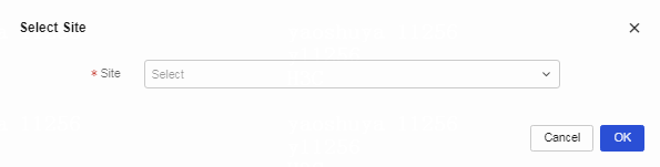
Table 5 In the confirmation dialog box that opens, click OK.
After the accounts are synchronized to the center device, you can select to authenticate branch VPNs on the center VPN when creating the center VPN. Select On for Branch VPN Auth to enable the center VPN to authenticate branch VPNs.
Figure 13 Enabling branch VPN authentication

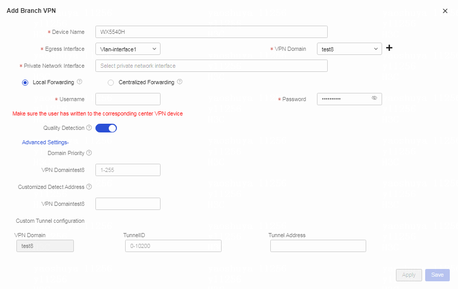
Table 6 With branch VPN authentication enabled, you must specify the authentication user and authentication password when adding a branch VPN. Create a branch VPN as follows:
a. Enter the name of the VPN account synchronized to the center device as the authentication account.
b. Enter the password of the VPN account.
c. Click Apply. After the branch VPN passes authentication, it can successfully establish a VPN tunnel with the center VPN.
Figure 14 Authenticating the branch VPN
(Optional) Configuring an IKE proposal
Table 7 On the VPN page, click the IKE Proposal tab. On the IKE Proposal page, you can see that a default IKE proposal exists. The default proposal uses the AES-CBC-256 encryption algorithm, SHA1 authentication algorithm, and DH group 1 for IKE.
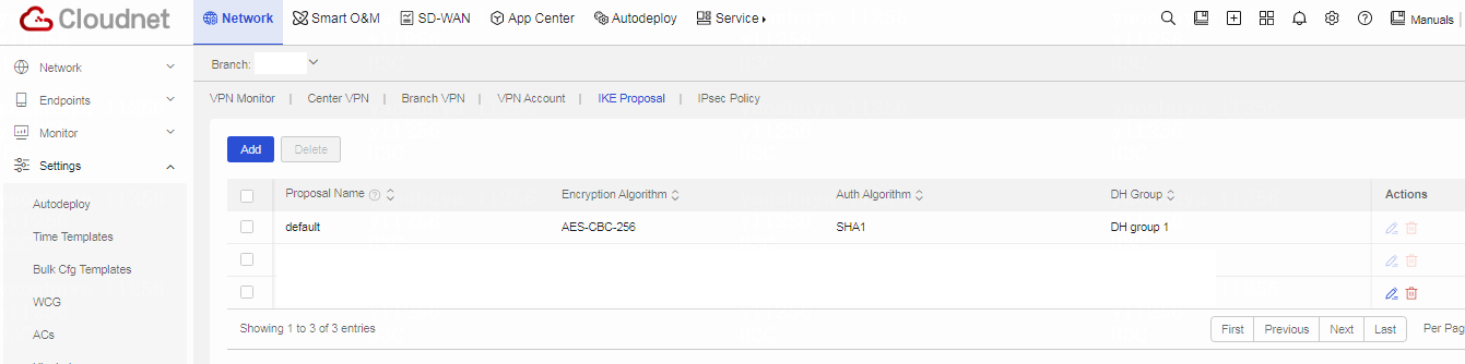
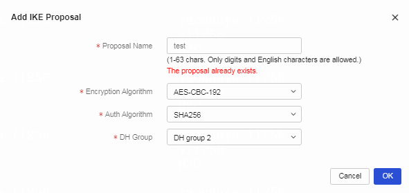
Table 8 Click Add. Configure the IKE proposal as follows:
a. Enter the IKE proposal name. In this example, the name is test.
b. Select the encryption algorithm. Available encryption algorithms include DES-CBC, DES-3DES, AES-CBC-128, AES-CBC-192, and AES-CBC-256. In this example, the encryption algorithm is set to AES-CBC-192.
c. Select the authentication algorithm. Available authentication algorithms include SHA1, MD5, SHA256, SHA384, and SHA512. In this example, the authentication algorithm is set to SHA256.
d. Select the DH group. Available DH groups include DH group1, DH group2, DH group5, DH group14, and DH group24. In this example, the DH group is set to DH group2.
e. Click OK.
Figure 16 Adding an IKE proposal
After successfully adding an IKE proposal, you can select the configured IKE proposal for the center VPN when you create the VPN. Select the configured IKE proposal. In this example, select IKE proposal test.
Figure 17 Selecting the configured IKE proposal for a center VPN

(Optional) Configuring an IPsec policy
Table 9 On the VPN page, click the IPsec Policy tab. On the IPsec Policy page, you can see that a default IPsec policy exists. The default IPsec policy uses the ESP security mode, MD5 authentication algorithm, and AES-CBC-256 encryption algorithm.
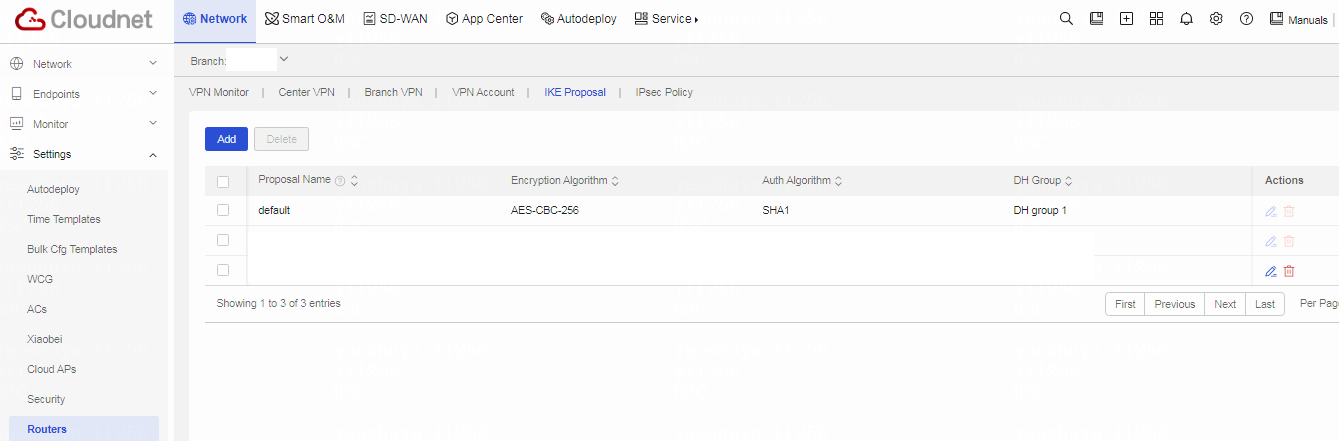
Table 10 Click Add. Configure the IPsec policy as follows:
a. Set the name of the IPsec policy. In this example, the policy name is test.
b. Set the security mode for the IPsec policy. Available security modes include ESP, AH, and ESP+AH. The AH mode does not support NAT traversal. If a NAT gateway exists in the network, use the ESP mode as a best practice. In this example, the security mode is set to ESP.
c. Set the ESP authentication algorithm. Available ESP authentication algorithms include MD5, SHA1, SHA256, SHA384, and SHA512. In this example, the ESP authentication algorithm is set to SHA1.
d. Set the ESP encryption algorithm. Available ESP encryption algorithms include DES-CBC, 3DES-CBC, AES-CBC-128, AES-CBC-192, and AES-CBC-256. In this example, the ESP encryption algorithm is set to AES-CBC-128.
e. Select whether to enable the PFS feature. In this example, this feature is disabled.
f. Click OK.
After successfully adding an IPsec policy, you can select the configured IPsec policy for the center VPN when you create the VPN. Select the configured IPsec policy. In this example, select IPsec policy test.
Figure 19 Selecting the configured IPsec policy for a center VPN

(Optional) Subscribing to tunnel state alarms
Table 1 Click Network on the top navigation bar, and then select Messages > Alarms from the left navigation pane.
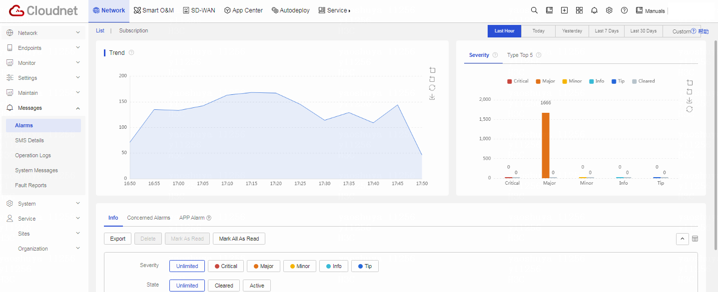
Table 2 Click the Subscription tab. You can see that a default alarm policy exists and the alarm push method is Not Push.
Figure 21 Alarm subscription page
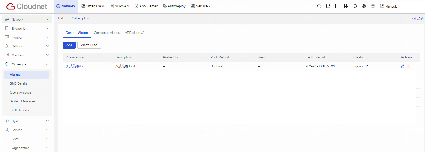
Table 3 Click Add. Configure the subscription policy. Parameters marked with a red asterisk are required.
Configure the alarm policy as follows:
a. Set the name of the alarm policy.
b. Set the alarm notification method.
c. Set notification time range from the Triggered field.
d. Specify the maintenance time range.
e. Select the alarm accounts. Select the target accounts, and then click the right chevron icon to add the accounts to the selected account list.
Figure 22 Configuring an alarm policy
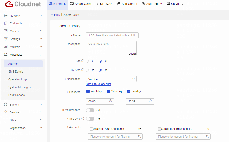
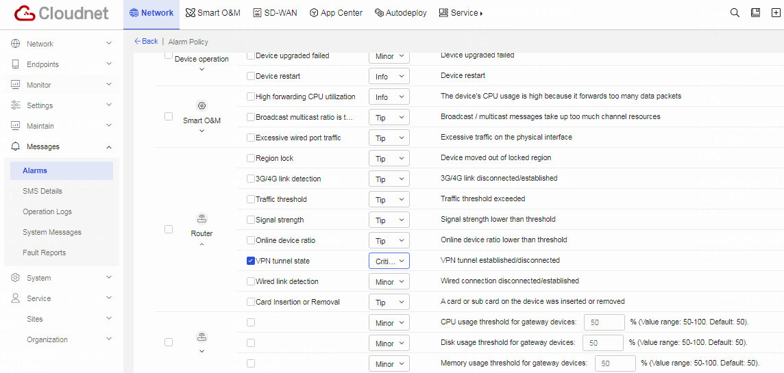
Table 4 In the Alarm Info section, select VPN tunnel state for Router category, and set the alarm severity to Critical. Click OK to save the configured alarm policy.
Figure 23 Configuring alarm details
Verifying the configuration
After you complete the above configuration, the center and the branch establish a VPN tunnel. On the VPN page, click the VPN Monitor tab, and view the state of the VPN tunnel.
Related documentation
· Security Configuration Guide in H3C MSR1000[2600][3600] Routers Configuration Guides(V9)
· Security Command Reference in H3C MSR1000[2600][3600] Routers Command References(V9)