- Table of Contents
-
- H3C MSR1000[2600][3600] Routers Configuration Examples All-in-One-R9141-6W100
- 00-Preface
- 01-Local 802.1X Authentication Configuration Examples
- 02-RADIUS-Based 802.1X Authentication Configuration Examples
- 03-AAA Configuration Examples
- 04-ACL Configuration Examples
- 05-MPLS over ADVPN Configuration Examples
- 06-ARP Attack Protection Configuration Examples
- 07-BFD Configuration Examples
- 08-Basic BGP Configuration Examples
- 09-BGP Route Attribute-Based Route Selection Configuration Examples
- 10-EAA Monitor Policy Configuration Examples
- 11-GRE with OSPF Configuration Examples
- 12-HoVPN Configuration Examples
- 13-IGMP Snooping Configuration Examples
- 14-IGMP Configuration Examples
- 15-IPsec Configuration Examples
- 16-IPsec Digital Certificate Authentication Configuration Examples
- 17-IPv6 IS-IS Configuration Examples
- 18-IPv6 over IPv4 GRE Tunnel Configuration Examples
- 19-IPv6 over IPv4 Manual Tunnel with OSPFv3 Configuration Examples
- 20-IS-IS Configuration Examples
- 21-Combined ISATAP Tunnel and 6to4 Tunnel Configuration Examples
- 22-L2TP over IPsec Configuration Examples
- 23-Multi-Instance L2TP Configuration Examples
- 24-L2TP Multidomain Access Configuration Examples
- 25-MPLS L3VPN Configuration Examples
- 26-MPLS OAM Configuration Examples
- 27-MPLS TE Configuration Examples
- 28-Basic MPLS Configuration Examples
- 29-NAT DNS Mapping Configuration Examples
- 30-NetStream Configuration Examples
- 31-NQA Configuration Examples
- 32-NTP Configuration Examples
- 33-OSPFv3 Configuration Examples
- 34-OSPF Configuration Examples
- 35-OSPF Multi-Process Configuration Examples
- 36-OSPF Multi-Instance Configuration Examples
- 37-Portal Configuration Examples
- 38-PPP Configuration Examples
- 39-RBAC Configuration Examples
- 40-RMON Configuration Examples
- 41-IPv4 NetStream Sampling Configuration Examples
- 42-SNMP Configuration Examples
- 43-SRv6 Configuration Examples
- 44-SSH Configuration Examples
- 45-Tcl Commands Configuration Examples
- 46-VLAN Configuration Examples
- 47-VRRP Configuration Examples
- 48-VXLAN over IPsec Configuration Examples
- 49-WLAN AC Configuration Examples
- 50-Small and Medium-Sized Store Configuration Examples
- 51-Cloudnet VPN Configuration Examples
- 52-Ethernet Link Aggregation Configuration Examples
- 53-Ethernet OAM Configuration Examples
- 54-Outbound Bidirectional NAT Configuration Examples
- 55-NAT Hairpin in C-S Mode Configuration Examples
- 56-Load Sharing NAT Server Configuration Examples
- 57-BIDIR-PIM Configuration Examples
- 58-Control Plane-Based QoS Policy Configuration Examples
- 59-Scheduling a Task Configuration Examples
- 60-Client-Initiated L2TP Tunnel Configuration Examples
- 61-LAC-Auto-Initiated L2TP Tunnel Configuration Examples
- 62-Authorized ARP Configuration Examples
- 63-GTS Configuration Examples
- 64-Traffic Policing Configuration Examples
- 65-Traffic Accounting Configuration Examples
- 66-Mobile Communication Modem Management Configuration Examples
- 67-Port Isolation Configuration Examples
- 68-PBR Configuration Examples
- 69-TFTP Client Software Upgrade Configuration Examples
- 70-FTP Client Software Upgrade Configuration Examples
- 71-FTP Server Software Upgrade Configuration Examples
- 72-Routing Policy Configuration Examples
- 73-Software Upgrade from the BootWare Menu Configuration Examples
- 74-Mirroring Configuration Examples
- Related Documents
-
| Title | Size | Download |
|---|---|---|
| 47-VRRP Configuration Examples | 335.43 KB |
VRRP Configuration Examples
Copyright © 2023 New H3C Technologies Co., Ltd. All rights reserved.
No part of this manual may be reproduced or transmitted in any form or by any means without prior written consent of New H3C Technologies Co., Ltd.
Except for the trademarks of New H3C Technologies Co., Ltd., any trademarks that may be mentioned in this document are the property of their respective owners.
The information in this document is subject to change without notice.
Contents
Example: Configuring a single VRRP group
Example: Configuring multiple VRRP groups
Example: Configuring VRRP load balancing
Example: Configuring VRRP with IPsec
Introduction
The following information provides an example for configuring Virtual Router Redundancy Protocol (VRRP) on routers.
Prerequisites
The following information applies to Comware 9-based routers. Procedures and information in the examples might be slightly different depending on the software or hardware version of the router.
The configuration examples were created and verified in a lab environment, and all the devices were started with the factory default configuration. When you are working on a live network, make sure you understand the potential impact of every command on your network.
The following information is provided based on the assumption that you have basic knowledge of VRRP, Spanning Tree Protocol (STP), and IPsec.
Example: Configuring a single VRRP group
Network configuration
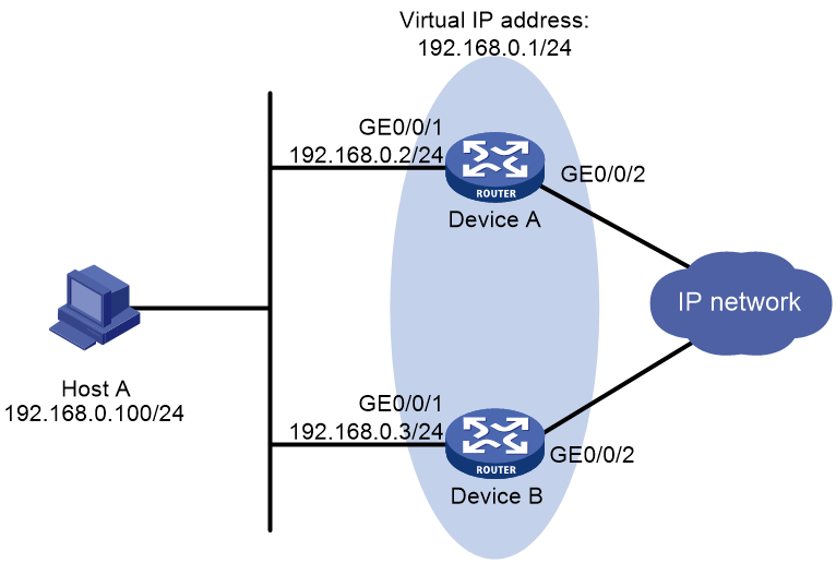
As shown in Figure 1, two gateway devices are deployed at the network egress of Host A. Device A and Device B form a VRRP group that acts as the default gateway for Host A. The network requirements are as follows:
· Device A operates as the master to forward packets from Host A to Host B.
· When Device A fails, Device B takes over to forward packets for Host A.
· When Device A recovers, Device A acts as the gateway again.
Analysis
· To enable Device A to become the master in the VRRP group, you need to configure a higher priority for Device A.
· To enable the master to automatically adjust its VRRP priority according to uplink interface state, configure preemption mode and uplink interface monitoring settings for the VRRP group. This configuration implements master/backup switchover upon a role change in the VRRP group.
· To avoid frequent role changes in the VRRP group, configure a preemption delay.
Software versions used
This configuration example was created and verified on R9141P16 of the MSR2630E-X1 device.
Restrictions and guidelines
· You cannot specify the virtual IP address as any of the following IP addresses:
¡ All-zero address (0.0.0.0).
¡ Broadcast address (255.255.255.255).
¡ Loopback address.
¡ IP address of other than Class A, Class B, and Class C.
¡ Invalid IP address (for example, 0.0.0.1).
· You can specify the IPv4 VRRP version as VRRPv2 or VRRPv3 (default version). For an IPv4 VRRP group to operate correctly, configure the same VRRP version for all routers in the IPv4 VRRP group.
· If you remove the VRRP group on an IP address owner, an IP address conflict will occur. To avoid the conflict, change the IP address of the interface on the IP address owner before you remove the VRRP group from the interface.
· Make sure all members in a VRRP group have the same virtual IP address configured.
· Make sure the reduced priority is lower than the priority of any other devices in the VRRP group, so that another device can be elected as master.
Procedures
Configuring Device A
# Configure an IP address for interface GigabitEthernet 0/0/1.
<DeviceA> system-view
[DeviceA] interface gigabitethernet 0/0/1
[DeviceA-GigabitEthernet0/0/1] ip address 192.168.0.2 24
# Create VRRP group 1 and configure the virtual IP address for VRRP group 1 as 192.168.0.1.
[DeviceA-GigabitEthernet0/0/1] vrrp vrid 1 virtual-ip 192.168.0.1
# Assign Device A a higher priority than Device B in VRRP group 1, so Device A can become the master.
[DeviceA-GigabitEthernet0/0/1] vrrp vrid 1 priority 110
# Configure Device A to operate in preemptive mode, so it can become the master whenever it operates correctly. Set the preemption delay to five seconds to avoid frequent status switchover.
[DeviceA-GigabitEthernet0/0/1] vrrp vrid 1 preempt-mode delay 5
[DeviceA-GigabitEthernet0/0/1] quit
# Create track entry 1 associated with the physical state of uplink interface GigabitEthernet 0/0/2.
[DeviceA] track 1 interface gigabitethernet 0/0/2
# Create track entry 1. When the track entry transits to Negative state, Device A decreases its priority by 50 in the VRRP group.
[DeviceA] interface gigabitethernet 0/0/1
[DeviceA-GigabitEthernet0/0/1] vrrp vrid 1 track 1 priority reduced 50
[DeviceA-GigabitEthernet0/0/1] quit
Configuring Device B
# Configure an IP address for interface GigabitEthernet 0/0/1.
[DeviceB] interface gigabitethernet 0/0/1
[DeviceB-GigabitEthernet0/0/1] ip address 192.168.0.3 24
# Create VRRP group 1 and configure the virtual IP address for VRRP group 1 as 192.168.0.1.
[DeviceB-GigabitEthernet0/0/1] vrrp vrid 1 virtual-ip 192.168.0.1
# Set the priority of Device B to 100 in VRRP group 1.
[DeviceB-GigabitEthernet0/0/1] vrrp vrid 1 priority 100
# Configure Device B to operate in preemptive mode, and set the preemption delay to five seconds.
[DeviceB-GigabitEthernet0/0/1] vrrp vrid 1 preempt-mode delay 5
[DeviceB-GigabitEthernet0/0/1] quit
Verifying the configuration
# Ping Host B from Host A. (Details not shown.)
# Display detailed information about VRRP group 1 on Device A.
[DeviceA] display vrrp verbose
IPv4 Virtual Router Information:
Running Mode : Standard
Total number of virtual routers : 1
Interface GigabitEthernet0/0/1
VRID : 1 Adver Timer : 100
Admin Status : Up State : Master
Config Pri : 110 Running Pri : 110
Preempt Mode : Yes Delay Time : 5
Auth Type : None
Virtual IP : 192.168.0.1
Virtual MAC : 0000-5e00-0101
Master IP : 192.168.0.2
VRRP Track Information:
Track Object : 1 State : Positive Pri Reduced : 50
# Display detailed information about VRRP group 1 on Device B.
[DeviceB] display vrrp verbose
IPv4 Virtual Router Information:
Running Mode : Standard
Total number of virtual routers : 1
Interface GigabitEthernet0/0/1
VRID : 1 Adver Timer : 100
Admin Status : Up State : Backup
Config Pri : 100 Running Pri : 100
Preempt Mode : Yes Delay Time : 5
Become Master : 412ms left
Auth Type : None
Virtual IP : 192.168.0.1
Master IP : 192.168.0.2
# When Device A fails, verify that Host A can still ping Host B. (Details not shown.)
# Display detailed information about VRRP group 1 on Device B.
[DeviceB] display vrrp verbose
IPv4 Virtual Router Information:
Running Mode : Standard
Total number of virtual routers : 1
Interface GigabitEthernet0/0/1
VRID : 1 Adver Timer : 100
Admin Status : Up State : Master
Config Pri : 100 Running Pri : 100
Preempt Mode : Yes Delay Time : 5
Auth Type : None
Virtual IP : 192.168.0.1
Virtual MAC : 0000-5e00-0101
Master IP : 192.168.0.3
# After Device A recovers, display detailed information about VRRP group 1 on Device A.
[DeviceA] display vrrp verbose
IPv4 Virtual Router Information:
Running Mode : Standard
Total number of virtual routers : 1
Interface GigabitEthernet0/0/1
VRID : 1 Adver Timer : 100
Admin Status : Up State : Master
Config Pri : 110 Running Pri : 110
Preempt Mode : Yes Delay Time : 5
Auth Type : None
Virtual IP : 192.168.0.1
Virtual MAC : 0000-5e00-0101
Master IP : 192.168.0.2
VRRP Track Information:
Track Object : 1 State : Positive Pri Reduced : 50
Configuration files
· Device A:
#
interface GigabitEthernet0/0/1
port link-mode route
ip address 192.168.0.2 255.255.255.0
vrrp vrid 1 virtual-ip 192.168.0.1
vrrp vrid 1 priority 110
vrrp vrid 1 preempt-mode delay 5
vrrp vrid 1 track 1 priority reduced 50
#
track 1 interface GigabitEthernet 0/0/2
#
· Device B:
#
interface GigabitEthernet0/0/1
port link-mode route
ip address 192.168.0.3 255.255.255.0
vrrp vrid 1 virtual-ip 192.168.0.1
vrrp vrid 1 priority 100
vrrp vrid 1 preempt-mode delay 5
#
Example: Configuring multiple VRRP groups
Network configuration
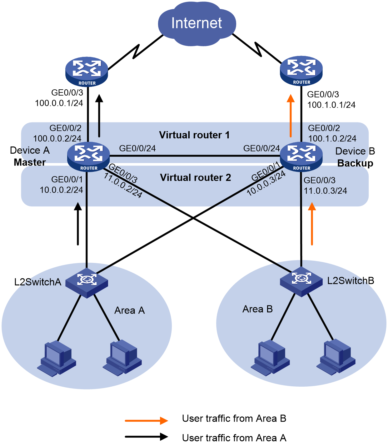
As shown in Figure 2, to achieve gateway redundancy and load balancing for internal host traffic, a company deploys two devices at the internal network egress. Two devices formed two VRRP groups in load balancing mode as default gateways for areas A and B, respectively. The network requirements are as follows:
· Device A operates as the master in VRRP group 1. Device B operates as the master in VRRP group 2. Typically, Device A forwards user data in area A, and Device B forwards user data in area B.
· When Device A or its uplink interface fails, Device B takes over to forward host traffic in area A. When Device A recovers, it acts as the gateway for VRRP group 1 again.
· When Device B or its uplink interface fails, Device A takes over to forward host traffic in area B. When Device B recovers, it acts as the gateway for VRRP group 2 again.
Analysis
· To enable Device A to become the master in VRRP group 1, you need to configure a higher priority for Device A in VRRP group 1. To enable Device B to become the master in VRRP group 2, you need to configure a higher priority for Device B in VRRP group 2.
· To avoid frequent role changes in the VRRP groups, configure a preemption delay.
Software versions used
This configuration example was created and verified on R9141P16 of the MSR2630E-X1 device.
Restrictions and guidelines
· You cannot specify the virtual IP address as any of the following IP addresses:
¡ All-zero address (0.0.0.0).
¡ Broadcast address (255.255.255.255).
¡ Loopback address.
¡ IP address of other than Class A, Class B, and Class C.
¡ Invalid IP address (for example, 0.0.0.1).
· You can specify the IPv4 VRRP version as VRRPv2 or VRRPv3 (default version). For an IPv4 VRRP group to operate correctly, configure the same VRRP version for all routers in the IPv4 VRRP group.
· If you remove the VRRP group on an IP address owner, an IP address conflict will occur. To avoid the conflict, change the IP address of the interface on the IP address owner before you remove the VRRP group from the interface.
· Make sure the reduced priority is lower than the priority of any other devices in the VRRP group, so that another device can be elected as master device.
· Make sure the following settings are consistent on all members in a VRRP group.
¡ Number of virtual IP addresses.
¡ Virtual IP address of the VRRP group.
¡ Timers.
Procedures
Configuring Device A
# Configure an IP address for interface GigabitEthernet 0/0/1.
<DeviceA> system-view
[DeviceA] interface gigabitethernet 0/0/1
[DeviceA-GigabitEthernet0/0/1] ip address 10.0.0.2 24
[DeviceA-GigabitEthernet0/0/1] quit
# Assign IP addresses to other interfaces in Figure 2 in the same way. (Details not shown.)
# Create VRRP group 1 and configure the virtual IP address for VRRP group 1 as 10.0.0.1. Assign Device A a higher priority than Device B in VRRP group 1, so Device A can become the master.
[DeviceA] interface gigabitethernet 0/0/1
[DeviceA-GigabitEthernet0/0/1] vrrp vrid 1 virtual-ip 10.0.0.1
[DeviceA-GigabitEthernet0/0/1] vrrp vrid 1 priority 120
[DeviceA-GigabitEthernet0/0/1] quit
# Create VRRP group 2 and configure the virtual IP address for VRRP group 2 as 11.0.0.1.
[DeviceA] interface gigabitethernet 0/0/3
[DeviceA-GigabitEthernet0/0/3] vrrp vrid 2 virtual-ip 11.0.0.1
[DeviceA-GigabitEthernet0/0/3] quit
# Configure Device A to operate in preemptive mode, and set the preemption delay to five seconds.
[DeviceA] interface gigabitethernet 0/0/1
[DeviceA-GigabitEthernet0/0/1] vrrp vrid 1 preempt-mode delay 5
[DeviceA-GigabitEthernet0/0/1] quit
# Create track entry 1 associated with the physical state of uplink interface GigabitEthernet 0/0/2.
[DeviceA] track 1 interface gigabitethernet 0/0/2
# Create track entry 1. When the track entry transits to Negative state, Device A decreases its priority by 50 in VRRP group 1.
[DeviceA] interface gigabitethernet 0/0/1
[DeviceA-GigabitEthernet0/0/1] vrrp vrid 1 track 1 priority reduced 50
[DeviceA-GigabitEthernet0/0/1] quit
Configuring Device B
<DeviceB> system-view
[DeviceB] interface gigabitethernet 0/0/1
[DeviceB-GigabitEthernet0/0/1] ip address 10.0.0.3 24
[DeviceB-GigabitEthernet0/0/1] quit
# Assign IP addresses to other interfaces in Figure 2 in the same way. (Details not shown.)
# Create VRRP group 1 and configure the virtual IP address for VRRP group 1 as 10.0.0.1.
[DeviceB] interface gigabitethernet 0/0/1
[DeviceB-GigabitEthernet0/0/1] vrrp vrid 1 virtual-ip 10.0.0.1
[DeviceB-GigabitEthernet0/0/1] quit
# Create VRRP group 2 and configure the virtual IP address for VRRP group 2 as 11.0.0.1. Assign Device B a higher priority than Device A in VRRP group 2, so Device B can become the master.
[DeviceB] interface gigabitethernet 0/0/3
[DeviceB-GigabitEthernet0/0/3] vrrp vrid 2 virtual-ip 11.0.0.1
[DeviceB-GigabitEthernet0/0/3] vrrp vrid 2 priority 120
# Configure Device B to operate in preemptive mode, and set the preemption delay to five seconds.
[DeviceB-GigabitEthernet0/0/3] vrrp vrid 2 preempt-mode delay 5
[DeviceB-GigabitEthernet0/0/3] quit
# Create track entry 2 associated with the physical state of uplink interface GigabitEthernet 0/0/2.
[DeviceB] track 2 interface gigabitethernet 0/0/2
# Create track entry 2. When the track entry transits to Negative state, Device B decreases its priority by 50 in VRRP group 2.
[DeviceB] interface gigabitethernet 0/0/3
[DeviceB-GigabitEthernet0/0/3] vrrp vrid 2 track 2 priority reduced 50
[DeviceB-GigabitEthernet0/0/3] quit
Verifying the configuration
1. Verify that the hosts in area A and area B can ping the external network.
# Ping 100.0.0.1 on host A in area A.
<host A> ping 100.0.0.1
PING 100.0.0.1 (100.0.0.1): 56 data bytes
56 bytes from 100.0.0.1: seq=0 ttl=128 time=22.43 ms
56 bytes from 100.0.0.1: seq=1 ttl=128 time=7.17 ms
56 bytes from 100.0.0.1: seq=2 ttl=128 time=8.91 ms
56 bytes from 100.0.0.1: seq=3 ttl=128 time=7.45 ms
56 bytes from 100.0.0.1: seq=4 ttl=128 time=9.11 ms
--- 100.0.0.1 ping statistics ---
5 packets transmitted, 5 packets received, 0% packet loss
round-trip min/avg/max = 7.17/11.01/22.43 ms
# Ping 100.1.0.1 on host C in area B.
<host C> ping 100.1.0.1
PING 100.1.0.1 (100.1.0.1): 56 data bytes
56 bytes from 100.1.0.1: seq=0 ttl=128 time=22.43 ms
56 bytes from 100.1.0.1: seq=1 ttl=128 time=7.17 ms
56 bytes from 100.1.0.1: seq=2 ttl=128 time=8.91 ms
56 bytes from 100.1.0.1: seq=3 ttl=128 time=7.45 ms
56 bytes from 100.1.0.1: seq=4 ttl=128 time=9.11 ms
--- 100.1.0.1 ping statistics ---
5 packets transmitted, 5 packets received, 0% packet loss
round-trip min/avg/max = 7.17/11.01/22.43 ms
2. Use the display vrrp verbose command to verify the configuration.
# Display detailed VRRP group information Device A. Verify that Device A is the master in VRRP group 1 and backup in VRRP group 2.
[DeviceA] display vrrp verbose
IPv4 Virtual Router Information:
Running Mode : Standard
Total number of virtual routers : 2
Interface GigabitEthernet0/0/1
VRID : 1 Adver Timer : 100
Admin Status : Up State : Master
Config Pri : 120 Running Pri : 120
Preempt Mode : Yes Delay Time : 5
Auth Type : None
Virtual IP : 10.0.0.1
Virtual MAC : 0000-5e00-0101
Master IP : 10.0.0.2
VRRP Track Information:
Track Object : 1 State : Positive Pri Reduced : 50
Interface GigabitEthernet0/0/3
VRID : 2 Adver Timer : 100
Admin Status : Up State : Backup
Config Pri : 100 Running Pri : 100
Preempt Mode : Yes Delay Time : 0
Auth Type : None
Become Master : 3550ms left
Virtual IP : 11.0.0.1
Master IP : 11.0.0.3
# Display detailed VRRP group information Device B. Verify that Device B is the backup in VRRP group 1 and master in VRRP group 2.
[DeviceB] display vrrp verbose
IPv4 Virtual Router Information:
Running Mode : Standard
Total number of virtual routers : 2
Interface GigabitEthernet0/0/1
VRID : 1 Adver Timer : 100
Admin Status : Up State : Backup
Config Pri : 100 Running Pri : 100
Preempt Mode : Yes Delay Time : 0
Auth Type : None
Become Master : 3500ms left
Virtual IP : 10.0.0.1
Master IP : 10.0.0.2
Interface GigabitEthernet0/0/3
VRID : 2 Adver Timer : 100
Admin Status : Up State : Master
Config Pri : 120 Running Pri : 120
Preempt Mode : Yes Delay Time : 5
Auth Type : None
Virtual IP : 11.0.0.1
Virtual MAC : 0000-5e00-0102
Master IP : 11.0.0.3
VRRP Track Information:
Track Object : 2 State : Positive Pri Reduced : 50
# When Device A becomes faulty, execute the display vrrp verbose command to display detailed VRRP group information on Device B. Verify that Device B preempts as the master in VRRP group 1.
[DeviceB] display vrrp verbose
IPv4 Virtual Router Information:
Running Mode : Standard
Total number of virtual routers : 2
Interface GigabitEthernet0/0/1
VRID : 1 Adver Timer : 100
Admin Status : Up State : Master
Config Pri : 100 Running Pri : 100
Preempt Mode : Yes Delay Time : 0
Auth Type : None
Virtual IP : 10.0.0.1
Virtual MAC : 0000-5e00-0101
Master IP : 10.0.0.3
Interface GigabitEthernet0/0/3
VRID : 2 Adver Timer : 100
Admin Status : Up State : Master
Config Pri : 120 Running Pri : 120
Preempt Mode : Yes Delay Time : 5
Auth Type : None
Virtual IP : 11.0.0.1
Virtual MAC : 0000-5e00-0102
Master IP : 11.0.0.3
VRRP Track Information:
Track Object : 2 State : Positive Pri Reduced : 50
The output shows that the hosts in area A and area B can still ping the external network when Device A becomes faulty.
# After Device A recovers, display detailed VRRP group information on Device A.
[DeviceA] display vrrp verbose
IPv4 Virtual Router Information:
Running Mode : Standard
Total number of virtual routers : 2
Interface GigabitEthernet0/0/1
VRID : 1 Adver Timer : 100
Admin Status : Up State : Master
Config Pri : 120 Running Pri : 120
Preempt Mode : Yes Delay Time : 5
Auth Type : None
Virtual IP : 10.0.0.1
Virtual MAC : 0000-5e00-0101
Master IP : 10.0.0.2
VRRP Track Information:
Track Object : 1 State : Positive Pri Reduced : 50
Interface GigabitEthernet0/0/3
VRID : 2 Adver Timer : 100
Admin Status : Up State : Backup
Config Pri : 100 Running Pri : 100
Preempt Mode : Yes Delay Time : 0
Become Master : 3550ms left
Auth Type : None
Virtual IP : 11.0.0.1
Master IP : 11.0.0.3
The output shows that after Device A recovers, it resumes the original priority and becomes the master in VRRP group 1 again to forward host traffic from area A to the external network.
Configuration files
· Device A:
#
interface GigabitEthernet0/0/1
port link-mode route
ip address 10.0.0.2 255.255.255.0
vrrp vrid 1 virtual-ip 10.0.0.1
vrrp vrid 1 priority 120
vrrp vrid 1 preempt-mode delay 5
vrrp vrid 1 track 1 priority reduced 50
#
interface GigabitEthernet0/0/2
port link-mode route
ip address 100.0.0.2 255.255.255.0
#
interface GigabitEthernet0/0/3
port link-mode route
ip address 11.0.0.2 255.255.255.0
vrrp vrid 2 virtual-ip 11.0.0.1
#
track 1 interface gigabitethernet 0/0/2
#
· Device B:
#
interface GigabitEthernet0/0/1
port link-mode route
ip address 10.0.0.3 255.255.255.0
vrrp vrid 1 virtual-ip 10.0.0.1
#
interface GigabitEthernet0/0/2
port link-mode route
ip address 100.1.0.2 255.255.255.0
#
interface GigabitEthernet0/0/3
port link-mode route
ip address 11.0.0.3 255.255.255.0
vrrp vrid 2 priority 120
vrrp vrid 2 preempt-mode delay 5
vrrp vrid 2 track 2 priority reduced 50
#
track 2 interface gigabitethernet 0/0/2
#
Example: Configuring VRRP load balancing
Network configuration
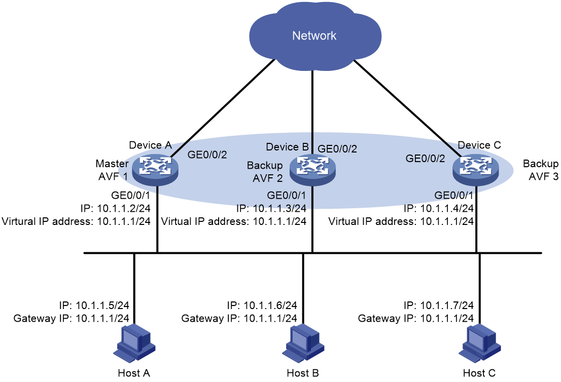
As shown in Figure 3, three routers are deployed at the network egresses of Host A, Host B, and Host C. Device A, Device B, and Device C form a load-balanced VRRP group that acts as the default gateways for LAN hosts. The network requirements are as follows:
· When Device A, Device B, or Device C or its uplink interface fails, Host A, Host B, and Host C can communicate through other devices that are operating correctly. When the failure is resolved, the faulty device can provide gateway services again.
Analysis
· For Device A to become the master in the VRRP group, configure a higher priority for Device A than Device B and Device C in the VRRP group. For Device B to become the master in the VRRP group, configure a higher priority for Device B than Device C in the VRRP group.
· To avoid frequent role changes in the VRRP group, configure a preemption delay.
· To monitor uplink interface state through track entries, configure VFs on Device A, Device B, and Device C. When an uplink interface failure occurs, the weights of the VFs on the faulty device decrease so another AVF can take over to avoid service interruption.
· For the original master to become the master again upon failure recovery, configure the VRRP group to operate in preemptive mode.
Software versions used
This configuration example was created and verified on R9141P16 of the MSR2630E-X1 device.
Restrictions and guidelines
· You cannot specify the virtual IP address as any of the following IP addresses:
¡ All-zero address (0.0.0.0).
¡ Broadcast address (255.255.255.255).
¡ Loopback address.
¡ IP address of other than Class A, Class B, and Class C.
¡ Invalid IP address (for example, 0.0.0.1).
· You can specify the IPv4 VRRP version as VRRPv2 or VRRPv3 (default version). For an IPv4 VRRP group to operate correctly, configure the same VRRP version for all routers in the IPv4 VRRP group.
· If you remove the VRRP group on an IP address owner, an IP address conflict will occur. To avoid the conflict, change the IP address of the interface on the IP address owner before you remove the VRRP group from the interface.
· For VRRP to operate correctly in load balancing mode, make sure the virtual IP address of an IPv4 VRRP group is not the IP address of any interfaces in the VRRP group.
· When the upstream link of the VF owner fails, an LVF must take over as the AVF. The switchover occurs when the weight of the VF owner drops below the lower limit of failure. This requires that the reduced weight for the VF owner be higher than 245.
· Make sure all members in a VRRP group have the same virtual IP address configured.
· Make sure the reduced priority is lower than the priority of any other devices in the VRRP group, so that another device can be elected as master.
Procedures
Configuring Device A
1. Configure an interface
# Configure an IP address for interface GigabitEthernet 0/0/1.
<DeviceA> system-view
[DeviceA] interface gigabitethernet 0/0/1
[DeviceA-GigabitEthernet0/0/1] ip address 10.1.1.2 24
[DeviceA-GigabitEthernet0/0/1] quit
2. Configure VRRP
# Specify the load balancing mode for IPv4 VRRP.
[DeviceA] vrrp mode load-balance
# Create VRRP group 1 and configure the virtual IP address for VRRP group 1 as 10.1.1.1.
[DeviceA] interface gigabitethernet 0/0/1
[DeviceA-GigabitEthernet0/0/1] vrrp vrid 1 virtual-ip 10.1.1.1
# Assign Device A a higher priority than Device B and Device C in VRRP group 1, so Device A can become the master.
[DeviceA-GigabitEthernet0/0/1] vrrp vrid 1 priority 120
# Configure Device A to operate in preemptive mode, so it can become the master whenever it operates correctly. Set the preemption delay to five seconds to avoid frequent status switchover.
[DeviceA-GigabitEthernet0/0/1] vrrp vrid 1 preempt-mode delay 5
[DeviceA-GigabitEthernet0/0/1] quit
3. Configure Track
# Create track entry 1 associated with the physical state of uplink interface GigabitEthernet 0/0/2. If the track entry state is Negative, the uplink interface of Device A becomes faulty.
[DeviceA] track 1 interface gigabitethernet 0/0/2
# Associate the VFs of IPv4 VRRP group 1 on GigabitEthernet 0/0/1 with track entry 1. Decrease the weight of all VFs on Device A in the VRRP group to drop below the lower limit of failure, so another device can take over. In this example, reduce the priority of the device in the VRRP group by 250.
[DeviceA] interface gigabitethernet 0/0/1
[DeviceA-GigabitEthernet0/0/1] vrrp vrid 1 track 1 weight reduced 250
[DeviceA-GigabitEthernet0/0/1] quit
Configuring Device B
1. Configure an interface
# Configure an IP address for interface GigabitEthernet 0/0/1.
<DeviceB> system-view
[DeviceB] interface gigabitethernet 0/0/1
[DeviceB-GigabitEthernet0/0/1] ip address 10.1.1.3 24
[DeviceB-GigabitEthernet0/0/1] quit
2. Configure VRRP
# Specify the load balancing mode for IPv4 VRRP.
[DeviceB] vrrp mode load-balance
# Create VRRP group 1 and configure the virtual IP address for VRRP group 1 as 10.1.1.1.
[DeviceB] interface gigabitethernet 0/0/1
[DeviceB-GigabitEthernet0/0/1] vrrp vrid 1 virtual-ip 10.1.1.1
# Assign Device B a higher priority than Device C in VRRP group 1, so B can become the master when Device A fails.
[DeviceB-GigabitEthernet0/0/1] vrrp vrid 1 priority 110
# Configure Device B to operate in preemptive mode, and set the preemption delay to five seconds.
[DeviceB-GigabitEthernet0/0/1] vrrp vrid 1 preempt-mode delay 5
[DeviceB-GigabitEthernet0/0/1] quit
3. Configure Track
# Create track entry 1 associated with the physical state of uplink interface GigabitEthernet 0/0/2. If the track entry state is Negative, the uplink interface of Device B becomes faulty.
[DeviceB] track 1 interface gigabitethernet 0/0/2
# Associate the VFs of IPv4 VRRP group 1 on GigabitEthernet 0/0/1 with track entry 1. Decrease the weight of all VFs on Device B in the VRRP group to drop below the lower limit of failure, so another device can take over. In this example, reduce the priority of the device in the VRRP group by 250.
[DeviceB] interface gigabitethernet 0/0/1
[DeviceB-GigabitEthernet0/0/1] vrrp vrid 1 track 1 weight reduced 250
[DeviceB-GigabitEthernet0/0/1] quit
Configuring Device C
1. Configure an interface
# Configure an IP address for interface GigabitEthernet 0/0/1.
<DeviceC> system-view
[DeviceC] interface gigabitethernet 0/0/1
[DeviceC-GigabitEthernet0/0/1] ip address 10.1.1.4 24
[DeviceC-GigabitEthernet0/0/1] quit
2. Configure VRRP
# Specify the load balancing mode for IPv4 VRRP.
[DeviceA] vrrp mode load-balance
# Create VRRP group 1 and configure the virtual IP address for VRRP group 1 as 10.1.1.1.
[DeviceC] interface gigabitethernet 0/0/1
[DeviceC-GigabitEthernet0/0/1] vrrp vrid 1 virtual-ip 10.1.1.1
# Configure Device C to operate in preemptive mode, and set the preemption delay to five seconds.
[DeviceC-GigabitEthernet0/0/1] vrrp vrid 1 preempt-mode delay 5
[DeviceC-GigabitEthernet0/0/1] quit
3. Configure Track
# Create track entry 1 associated with the physical state of uplink interface GigabitEthernet 0/0/2. If the track entry state is Negative, the uplink interface of Device C becomes faulty.
[DeviceC] track 1 interface gigabitethernet 0/0/2
# Associate the VFs of IPv4 VRRP group 1 on GigabitEthernet 0/0/1 with track entry 1. Decrease the weight of all VFs on Device C in the VRRP group to drop below the lower limit of failure, so another device can take over. In this example, reduce the priority of the device in the VRRP group by 250.
[DeviceC] interface gigabitethernet 0/0/1
[DeviceC-GigabitEthernet0/0/1] vrrp vrid 1 track 1 weight reduced 250
[DeviceC-GigabitEthernet0/0/1] quit
Verifying the configuration
1. After configuration, verify that you can ping the external network on Host A, and use the display vrrp verbose command to view the configuration result.
# Display detailed VRRP group information on Device A.
[DeviceA] display vrrp verbose
IPv4 Virtual Device Information:
Running Mode : Load Balance
Total number of virtual routers : 1
Interface GigabitEthernet0/0/1
VRID : 1 Adver Timer : 100
Admin Status : Up State : Master
Config Pri : 120 Running Pri : 120
Preempt Mode : Yes Delay Time : 5
Auth Type : None
Virtual IP : 10.1.1.1
Member IP List : 10.1.1.2 (Local, Master)
10.1.1.3 (Backup)
10.1.1.4 (Backup)
Forwarder Information: 3 Forwarders 1 Active
Config Weight : 255
Running Weight : 255
Forwarder 01
State : Active
Virtual MAC : 000f-e2ff-0011 (Owner)
Owner ID : 0000-5e01-1101
Priority : 255
Active : local
Forwarder 02
State : Listening
Virtual MAC : 000f-e2ff-0012 (Learnt)
Owner ID : 0000-5e01-1103
Priority : 127
Active : 10.1.1.3
Forwarder 03
State : Listening
Virtual MAC : 000f-e2ff-0013 (Learnt)
Owner ID : 0000-5e01-1105
Priority : 127
Active : 10.1.1.4
Forwarder Weight Track Information:
Track Object : 1 State : Positive Weight Reduced : 250
# Display detailed VRRP group information on Device B.
[DeviceB] display vrrp verbose
IPv4 Virtual Device Information:
Running Mode : Load Balance
Total number of virtual routers : 1
Interface GigabitEthernet0/0/1
VRID : 1 Adver Timer : 100
Admin Status : Up State : Backup
Config Pri : 110 Running Pri : 110
Preempt Mode : Yes Delay Time : 5
Auth Type : None
Virtual IP : 10.1.1.1
Member IP List : 10.1.1.3 (Local, Backup)
10.1.1.2 (Master)
10.1.1.4 (Backup)
Forwarder Information: 3 Forwarders 1 Active
Config Weight : 255
Running Weight : 255
Forwarder 01
State : Listening
Virtual MAC : 000f-e2ff-0011 (Learnt)
Owner ID : 0000-5e01-1101
Priority : 127
Active : 10.1.1.2
Forwarder 02
State : Active
Virtual MAC : 000f-e2ff-0012 (Owner)
Owner ID : 0000-5e01-1103
Priority : 255
Active : local
Forwarder 03
State : Listening
Virtual MAC : 000f-e2ff-0013 (Learnt)
Owner ID : 0000-5e01-1105
Priority : 127
Active : 10.1.1.4
Forwarder Weight Track Information:
Track Object : 1 State : Positive Weight Reduced : 250
# Display detailed VRRP group information on Device C.
[DeviceC] display vrrp verbose
IPv4 Virtual Device Information:
Running Mode : Load Balance
Total number of virtual routers : 1
Interface GigabitEthernet0/0/1
VRID : 1 Adver Timer : 100
Admin Status : Up State : Backup
Config Pri : 100 Running Pri : 100
Preempt Mode : Yes Delay Time : 5
Auth Type : None
Virtual IP : 10.1.1.1
Member IP List : 10.1.1.4 (Local, Backup)
10.1.1.2 (Master)
10.1.1.3 (Backup)
Forwarder Information: 3 Forwarders 1 Active
Config Weight : 255
Running Weight : 255
Forwarder 01
State : Listening
Virtual MAC : 000f-e2ff-0011 (Learnt)
Owner ID : 0000-5e01-1101
Priority : 127
Active : 10.1.1.2
Forwarder 02
State : Listening
Virtual MAC : 000f-e2ff-0012 (Learnt)
Owner ID : 0000-5e01-1103
Priority : 127
Active : 10.1.1.3
Forwarder 03
State : Active
Virtual MAC : 000f-e2ff-0013 (Owner)
Owner ID : 0000-5e01-1105
Priority : 255
Active : local
Forwarder Weight Track Information:
Track Object : 1 State : Positive Weight Reduced : 250
The output shows that Device A is operating as the master in VRRP group 1, and Device B and Device C are backups. Device A, Device B, and Device C each has an AVF and two LVFs as backups.
2. Verify the configuration after uplink interface GigabitEthernet 0/0/2 of Device A fails
# Display detailed VRRP group information on Device A.
[DeviceA] display vrrp verbose
IPv4 Virtual Device Information:
Running Mode : Load Balance
Total number of virtual routers : 1
Interface GigabitEthernet0/0/1
VRID : 1 Adver Timer : 100
Admin Status : Up State : Master
Config Pri : 120 Running Pri : 120
Preempt Mode : Yes Delay Time : 5
Auth Type : None
Virtual IP : 10.1.1.1
Member IP List : 10.1.1.2 (Local, Master)
10.1.1.3 (Backup)
10.1.1.4 (Backup)
Forwarder Information: 3 Forwarders 0 Active
Config Weight : 255
Running Weight : 5
Forwarder 01
State : Initialize
Virtual MAC : 000f-e2ff-0011 (Owner)
Owner ID : 0000-5e01-1101
Priority : 0
Active : 10.1.1.4
Forwarder 02
State : Initialize
Virtual MAC : 000f-e2ff-0012 (Learnt)
Owner ID : 0000-5e01-1103
Priority : 0
Active : 10.1.1.3
Forwarder 03
State : Initialize
Virtual MAC : 000f-e2ff-0013 (Learnt)
Owner ID : 0000-5e01-1105
Priority : 0
Active : 10.1.1.4
Forwarder Weight Track Information:
Track Object : 1 State : Negative Weight Reduced : 250
# Display detailed VRRP group information on Device C.
[DeviceC] display vrrp verbose
IPv4 Virtual Device Information:
Running Mode : Load Balance
Total number of virtual routers : 1
Interface GigabitEthernet0/0/1
VRID : 1 Adver Timer : 100
Admin Status : Up State : Backup
Config Pri : 100 Running Pri : 100
Preempt Mode : Yes Delay Time : 5
Auth Type : None
Become Master : 3550ms left
Virtual IP : 10.1.1.1
Member IP List : 10.1.1.4 (Local, Backup)
10.1.1.2 (Master)
10.1.1.3 (Backup)
Forwarder Information: 3 Forwarders 2 Active
Config Weight : 255
Running Weight : 255
Forwarder 01
State : Active
Virtual MAC : 000f-e2ff-0011 (Take Over)
Owner ID : 0000-5e01-1101
Priority : 85
Active : local
Redirect Time : 93 secs
Time-out Time : 1293 secs
Forwarder 02
State : Listening
Virtual MAC : 000f-e2ff-0012 (Learnt)
Owner ID : 0000-5e01-1103
Priority : 85
Active : 10.1.1.3
Forwarder 03
State : Active
Virtual MAC : 000f-e2ff-0013 (Owner)
Owner ID : 0000-5e01-1105
Priority : 255
Active : local
Forwarder Weight Track Information:
Track Object : 1 State : Positive Weight Reduced : 250
The output shows that when the uplink interface of Device A fails, the VF weights on Device A decreases to 5, which is lower than the lower limit of failure. All VFs on Device A change to Initialized and cannot forward packets. Device C becomes the AVF associated with virtual MAC address 000f-e2ff-0011, and takes over the forwarding task for Device A.
# Upon expiration of the timeout timer (1800 seconds), display detailed VRRP group information on Device C.
[DeviceC] display vrrp verbose
IPv4 Virtual Device Information:
Running Mode : Load Balance
Total number of virtual routers : 1
Interface GigabitEthernet0/0/1
VRID : 1 Adver Timer : 100
Admin Status : Up State : Backup
Config Pri : 100 Running Pri : 100
Preempt Mode : Yes Delay Time : 5
Auth Type : None
Become Master : 3550ms left
Virtual IP : 10.1.1.1
Member IP List : 10.1.1.4 (Local, Backup)
10.1.1.2 (Master)
10.1.1.3 (Backup)
Forwarder Information: 2 Forwarders 1 Active
Config Weight : 255
Running Weight : 255
Forwarder 02
State : Listening
Virtual MAC : 000f-e2ff-0012 (Learnt)
Owner ID : 0000-5e01-1103
Priority : 127
Active : 10.1.1.3
Forwarder 03
State : Active
Virtual MAC : 000f-e2ff-0013 (Owner)
Owner ID : 0000-5e01-1105
Priority : 255
Active : local
Forwarder Weight Track Information:
Track Object : 1 State : Positive Weight Reduced : 250
The output shows that when the timeout timer expires, the VF for virtual MAC address 000f-e2ff-0011 is removed. The VF no longer forwards the packets destined for the MAC address.
3. When Router A fails, display detailed VRRP group information on Device B.
[DeviceB] display vrrp verbose
IPv4 Standby Information:
Run Mode : Load Balance
Run Method : Virtual MAC
Total number of virtual routers : 1
Interface GigabitEthernet0/0/1
VRID : 1 Adver Timer : 1
Admin Status : Up State : Master
Config Pri : 110 Running Pri : 110
Preempt Mode : Yes Delay Time : 5
Auth Type : None
Virtual IP : 10.1.1.1
Member IP List : 10.1.1.3 (Local, Master)
10.1.1.4 (Backup)
Forwarder Information: 2 Forwarders 1 Active
Config Weight : 255
Running Weight : 255
Forwarder 02
State : Active
Virtual MAC : 000f-e2ff-0012 (Owner)
Owner ID : 0000-5e01-1103
Priority : 255
Active : local
Forwarder 03
State : Listening
Virtual MAC : 000f-e2ff-0013 (Learnt)
Owner ID : 0000-5e01-1105
Priority : 127
Active : 10.1.1.4
Forwarder Weight Track Information:
Track Object : 1 State : Positive Weight Reduced : 250
The output shows that when Device A fails, Device B becomes the master because it has a higher priority than Device C.
Configuration files
· Device A:
#
vrrp mode load-balance
#
interface GigabitEthernet0/0/1
port link-mode route
ip address 10.1.1.2 255.255.255.0
vrrp vrid 1 virtual-ip 10.1.1.1
vrrp vrid 1 priority 120
vrrp vrid 1 preempt-mode delay 5
vrrp vrid 1 track 1 weight reduced 250
#
track 1 interface GigabitEthernet0/0/2
· Device B:
#
vrrp mode load-balance
#
interface GigabitEthernet0/0/1
port link-mode route
ip address 10.1.1.3 255.255.255.0
vrrp vrid 1 virtual-ip 10.1.1.1
vrrp vrid 1 priority 110
vrrp vrid 1 preempt-mode delay 5
vrrp vrid 1 track 1 weight reduced 250
#
track 1 interface GigabitEthernet0/0/2
· Device C:
#
vrrp mode load-balance
#
interface GigabitEthernet0/0/1
port link-mode route
ip address 10.1.1.4 255.255.255.0
vrrp vrid 1 virtual-ip 10.1.1.1
vrrp vrid 1 preempt-mode delay 5
vrrp vrid 1 track 1 weight reduced 250
#
track 1 interface GigabitEthernet0/0/2
Example: Configuring VRRP with IPsec
Network configuration
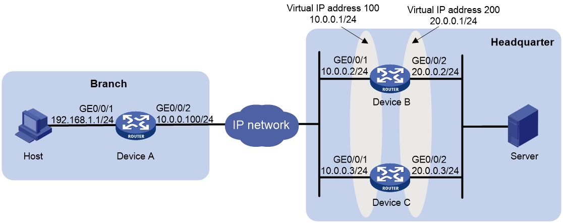
As shown in Figure 4, Device A is the gateway for an enterprise branch, and Device B and Device C are gateways for the enterprise headquarters. Configure VRRP on Device B and Device C to implement device redundancy backup for higher reliability. Hosts within the branch can access resources on internal servers at the enterprise headquarters. The network requirements are as follows:
· In normal situation, Device B acts as the master to forward traffic.
· When Device B fails, Device C takes over the traffic forwarding for Device B.
· Deploy an IPsec tunnel between Device A and the enterprise headquarters egress gateway for data integrity and confidentiality between branch network 192.168.1.0/24 and the headquarters network 20.0.0.0/24.
Analysis
· To ensure security of data between hosts and servers, establish a point-to-point IPsec tunnel between Device A and the master in VRRP group 100.
· To prevent IPsec tunnel interruption due to switchover in the VRRP group, configure Dead Peer Detection (DPD) to ensure that Device A can detect the peer router status in time and perform IKE renegotiation with other routers in the VRRP group.
· To enable Device B to become the master in the VRRP group, you need to configure a higher priority for B.
· To enable the master to automatically adjust its VRRP priority according to state of interface GigabitEthernet 0/0/2 connected to the headquarters internal network, configure preemption mode and uplink interface monitoring settings for the VRRP group. This configuration implements master/backup switchover upon a role change in the VRRP group.
· To avoid frequent role changes in the VRRP groups, configure a preemption delay.
Software versions used
This configuration example was created and verified on R9141P16 of the MSR2630E-X1 device.
Restrictions and guidelines
· You cannot specify the virtual IP address as any of the following IP addresses:
¡ All-zero address (0.0.0.0).
¡ Broadcast address (255.255.255.255).
¡ Loopback address.
¡ IP address of other than Class A, Class B, and Class C.
¡ Invalid IP address (for example, 0.0.0.1).
· You can specify the IPv4 VRRP version as VRRPv2 or VRRPv3 (default version). For an IPv4 VRRP group to operate correctly, configure the same VRRP version for all routers in the IPv4 VRRP group.
· If you remove the VRRP group on an IP address owner, an IP address conflict will occur. To avoid the conflict, change the IP address of the interface on the IP address owner before you remove the VRRP group from the interface.
· Make sure the source and destination addresses are consistent in the ACLs configured on both end of the IPsec tunnel.
· Make sure the pre-shared keys are the same on both ends of IKE negotiation.
· Make sure all members in a VRRP group have the same virtual IP address.
· Make sure the reduced priority is lower than the priority of any other devices in the VRRP group, so that another device can be elected as the master.
Procedures
Configuring Device A
# Configure IP addresses for interfaces.
<DeviceA> system-view
[DeviceA] interface gigabitethernet 0/0/1
[DeviceA-GigabitEthernet0/0/1] ip address 192.168.1.1 255.255.255.0
[DeviceA-GigabitEthernet0/0/1] quit
[DeviceA] interface gigabitethernet 0/0/2
[DeviceA-GigabitEthernet0/0/2] ip address 10.0.0.100 255.255.255.0
[DeviceA-GigabitEthernet0/0/2] quit
# Configure a static route destined to network 20.0.0.0/24.
[DeviceA] ip route-static 20.0.0.0 255.255.255.0 10.0.0.1
# Create ACL 3000 to identify data flows from subnet 192.168.1.0/24 to subnet 20.0.0.0/24.
[DeviceA] acl number 3000
[DeviceA-acl-adv-3000] rule 0 permit ip source 192.168.1.0 0.0.0.255 destination 20.0.0.0 0.0.0.255
[DeviceA-acl-adv-3000] quit
# Configure DPD to be triggered every 10 seconds and every 5 seconds between retries if the peer does not respond.
[DeviceA] ike dpd interval 10 retry 5 on-demand
# Create IKE keychain test, and set the preshared key to be used for IKE negotiation with peer 10.0.0.1 to 123456.
[DeviceA] ike keychain test
[DeviceA-ike-keychain-test] pre-shared-key address 10.0.0.1 key simple 123456
[DeviceA-ike-keychain-test] quit
# Create an IKE profile named test, specify IKE keychain test, configure the local ID with the identity type as IP address and the value as 10.0.0.100, and specify IP address 10.0.0.1 as the peer ID.
[DeviceA] ike profile test
[DeviceA-ike-profile-test] keychain test
[DeviceA-ike-profile-test] local-identity address 10.0.0.100
[DeviceA-ike-profile-test] match remote identity address 10.0.0.1
[DeviceA-ike-profile-test] quit
# Create an IPsec transform set named test, and use the default encapsulation mode and security protocol settings.
[DeviceA] ipsec transform-set test
# Specify the encryption and authentication algorithms for ESP as DES (64-bit key) and MD5, respectively.
[DeviceA-ipsec-transform-set-test] esp encryption-algorithm des-cbc
[DeviceA-ipsec-transform-set-test] esp authentication-algorithm md5
[DeviceA-ipsec-transform-set-test] quit
# Create an IKE-based IPsec policy entry with name test and sequence number 1.
[DeviceA] ipsec policy test 1 isakmp
# Specify the local IP address of the IPsec tunnel as 10.0.0.100.
[DeviceA-ipsec-policy-isakmp-test-1] local-address 10.0.0.100
# Specify the remote IP address of the IPsec tunnel as 10.0.0.1.
[DeviceA-ipsec-policy-isakmp-test-1] remote-address 10.0.0.1
# Apply ACL 3000.
[DeviceA-ipsec-policy-isakmp-test-1] security acl 3000
# Apply IPsec transform set test.
[DeviceA-ipsec-policy-isakmp-test-1] transform-set test
# Apply IKE profile test.
[DeviceA-ipsec-policy-isakmp-test-1] ike-profile test
[DeviceA-ipsec-policy-isakmp-test-1] quit
# Apply IPsec policy test to GigabitEthernet 0/0/2.
[DeviceA] interface gigabitethernet 0/0/2
[DeviceA-GigabitEthernet0/0/2] ipsec apply policy test
[DeviceA-GigabitEthernet0/0/2] quit
Configuring Device B
# Configure IP addresses for interfaces.
<DeviceB> system-view
[DeviceB] interface gigabitethernet 0/0/1
[DeviceB-GigabitEthernet0/0/1] ip address 10.0.0.2 255.255.255.0
[DeviceB-GigabitEthernet0/0/1] quit
[DeviceB] interface gigabitethernet 0/0/2
[DeviceB-GigabitEthernet0/0/2] ip address 20.0.0.2 255.255.255.0
[DeviceB-GigabitEthernet0/0/2] quit
# Configure a static route destined to network 192.168.1.0/24.
[DeviceB] ip route-static 192.168.1.0 255.255.255.0 10.0.0.100
# Create ACL 3000 to identify data flows from subnet 20.0.0.0/24 to subnet 192.168.1.0/24.
[DeviceB] acl number 3000
[DeviceB-acl-adv-3000] rule 0 permit ip source 20.0.0.0 0.0.0.255 destination 192.168.1.0 0.0.0.255
[DeviceB-acl-adv-3000] quit
# Create IKE keychain test, and set the preshared key to be used for IKE negotiation with peer 10.0.0.100 to 123456.
[DeviceB] ike keychain test
[DeviceB-ike-keychain-test] pre-shared-key address 10.0.0.100 key simple 123456
[DeviceB-ike-keychain-test] quit
# Create an IKE profile named test, specify IKE keychain test, configure the local ID with the identity type as IP address and the value as 10.0.0.1, and specify IP address 10.0.0.100 (IP address of the uplink interface of Device A) as the peer ID.
[DeviceB] ike profile test
[DeviceB-ike-profile-test] keychain test
[DeviceB-ike-profile-test] local-identity address 10.0.0.1
[DeviceB-ike-profile-test] match remote identity address 10.0.0.100
[DeviceB-ike-profile-test] quit
# Create an IPsec transform set named test, and use the default encapsulation mode and security protocol settings.
[DeviceB] ipsec transform-set test
# Specify the encryption and authentication algorithms for ESP as DES (64-bit key) and MD5, respectively.
[DeviceB-ipsec-transform-set-test] esp encryption-algorithm des-cbc
[DeviceB-ipsec-transform-set-test] esp authentication-algorithm md5
[DeviceB-ipsec-transform-set-test] quit
# Create an IKE-based IPsec policy entry with name test and sequence number 1.
[DeviceB] ipsec policy test 1 isakmp
# Specify the local IP address of the IPsec tunnel as 10.0.0.1.
[DeviceB-ipsec-policy-isakmp-test-1] local-address 10.0.0.1
# Specify the remote IP address of the IPsec tunnel as 10.0.0.100.
[DeviceB-ipsec-policy-isakmp-test-1] remote-address 10.0.0.100
# Apply ACL 3000.
[DeviceB-ipsec-policy-isakmp-test-1] security acl 3000
# Apply IPsec transform set test.
[DeviceB-ipsec-policy-isakmp-test-1] transform-set test
# Apply IKE profile test.
[DeviceB-ipsec-policy-isakmp-test-1] ike-profile test
[DeviceB-ipsec-policy-isakmp-test-1] quit
# Apply IPsec policy test to GigabitEthernet 0/0/1.
[DeviceB] interface gigabitethernet 0/0/1
[DeviceB-GigabitEthernet0/0/1] ipsec apply policy test
[DeviceB-GigabitEthernet0/0/1] quit
# Create track entry 1 to monitor the state of interface GigabitEthernet 0/0/2.
[DeviceB] track 1 interface gigabitethernet 0/0/2
# Create VRRP group 100, and configure the virtual IP address for VRRP group 100 as 10.0.0.1.
[DeviceB] interface gigabitethernet 0/0/1
[DeviceB-GigabitEthernet0/0/1] vrrp vrid 100 virtual-ip 10.0.0.1
# Set the priority of Device B to 150 in VRRP group 100.
[DeviceB-GigabitEthernet0/0/1] vrrp vrid 100 priority 150
# Create track entry 1. When the track entry transits to Negative state, Device B decreases its priority by 60 (lower than the default priority 100) in VRRP group 100.
[DeviceB-GigabitEthernet0/0/1] vrrp vrid 100 track 1 priority reduce 60
[DeviceB-GigabitEthernet0/0/1] quit
# Create track entry 2 to monitor the state of interface GigabitEthernet 0/0/1.
[DeviceB] track 2 interface gigabitethernet 0/0/1
# Create VRRP group 200, and configure the virtual IP address for VRRP group 200 as 20.0.0.1.
[DeviceB] interface gigabitethernet 0/0/2
[DeviceB-GigabitEthernet0/0/2] vrrp vrid 200 virtual-ip 20.0.0.1
# Set the priority of Device B to 150 in VRRP group 200.
[DeviceB-GigabitEthernet0/0/2] vrrp vrid 200 priority 150
# Create track entry 2. When the track entry transits to Negative state, Device B decreases its priority by 60 (lower than the default priority 100) in VRRP group 200.
[DeviceB-GigabitEthernet0/0/2] vrrp vrid 200 track 2 priority reduce 60
[DeviceB-GigabitEthernet0/0/2] quit
Configuring Device C
# Configure IP addresses for interfaces.
<DeviceC> system-view
[DeviceC] interface gigabitethernet 0/0/1
[DeviceC-GigabitEthernet0/0/1] ip address 10.0.0.3 255.255.255.0
[DeviceC-GigabitEthernet0/0/1] quit
[DeviceC] interface gigabitethernet 0/0/2
[DeviceC-GigabitEthernet0/0/2] ip address 20.0.0.3 255.255.255.0
[DeviceC-GigabitEthernet0/0/2] quit
# Configure a static route destined to network 192.168.1.0/24.
[DeviceC] ip route-static 192.168.1.0 255.255.255.0 10.0.0.100
# Create ACL 3000 to identify data flows from subnet 20.0.0.0/24 to subnet 192.168.1.0/24.
[DeviceC] acl number 3000
[DeviceC-acl-adv-3000] rule 0 permit ip source 20.0.0.0 0.0.0.255 destination 192.168.1.0 0.0.0.255
[DeviceC-acl-adv-3000] quit
# Create IKE keychain test, and set the preshared key to be used for IKE negotiation with peer 10.0.0.100 to 123456.
[DeviceC] ike keychain test
[DeviceC-ike-keychain-test] pre-shared-key address 10.0.0.100 key simple 123456
[DeviceC-ike-keychain-test] quit
# Create an IKE profile named test, specify IKE keychain test, configure the local ID with the identity type as IP address and the value as 10.0.0.1, and specify IP address 10.0.0.100 (IP address of the uplink interface of Device A) as the peer ID.
[DeviceC] ike profile test
[DeviceC-ike-profile-test] keychain test
[DeviceC-ike-profile-test] local-identity address 10.0.0.1
[DeviceC-ike-profile-test] match remote identity address 10.0.0.100
[DeviceC-ike-profile-test] quit
# Create an IPsec transform set named test, and use the default encapsulation mode and security protocol settings.
[DeviceC] ipsec transform-set test
# Specify the encryption and authentication algorithms for ESP as DES (64-bit key) and MD5, respectively.
[DeviceC-ipsec-transform-set-test] esp encryption-algorithm des-cbc
[DeviceC-ipsec-transform-set-test] esp authentication-algorithm md5
[DeviceC-ipsec-transform-set-test] quit
# Create an IKE-based IPsec policy entry with name test and sequence number 1.
[DeviceC] ipsec policy test 1 isakmp
# Specify the local IP address of the IPsec tunnel as 10.0.0.1.
[DeviceC-ipsec-policy-isakmp-test-1] local-address 10.0.0.1
# Specify the remote IP address of the IPsec tunnel as 10.0.0.100.
[DeviceC-ipsec-policy-isakmp-test-1] remote-address 10.0.0.100
# Apply ACL 3000.
[DeviceC-ipsec-policy-isakmp-test-1] security acl 3000
# Apply IPsec transform set test.
[DeviceC-ipsec-policy-isakmp-test-1] transform-set test
# Apply IKE profile test.
[DeviceC-ipsec-policy-isakmp-test-1] ike-profile test
[DeviceC-ipsec-policy-isakmp-test-1] quit
# Apply IPsec policy test to GigabitEthernet 0/0/1.
[DeviceC] interface gigabitethernet 0/0/1
[DeviceC-GigabitEthernet0/0/1] ipsec apply policy test
[DeviceC-GigabitEthernet0/0/1] quit
# Create VRRP group 100, and configure the virtual IP address for VRRP group 100 as 10.0.0.1.
[DeviceC] interface gigabitethernet 0/0/1
[DeviceC-GigabitEthernet0/0/1] vrrp vrid 100 virtual-ip 10.0.0.1
[DeviceC-GigabitEthernet0/0/1] quit
# Create VRRP group 200, and configure the virtual IP address for VRRP group 200 as 20.0.0.1.
[DeviceC] interface gigabitethernet 0/0/2
[DeviceC-GigabitEthernet0/0/2] vrrp vrid 200 virtual-ip 20.0.0.1
[DeviceC-GigabitEthernet0/0/2] quit
Verifying the configuration
1. View detailed VRRP group information on Device B and Device C. Verify that Device B is the master in VRRP groups 100 and 200, and Device C is the backup.
# Display detailed VRRP group information on Device B.
[DeviceB] display vrrp verbose
IPv4 Virtual Router Information:
Running Mode : Standard
Total number of virtual routers : 2
Interface GigabitEthernet0/0/1
VRID : 100 Adver Timer : 100
Admin Status : Up State : Master
Config Pri : 150 Running Pri : 150
Preempt Mode : Yes Delay Time : 0
Auth Type : None
Virtual IP : 10.0.0.1
Virtual MAC : 0000-5e00-0164
Master IP : 10.0.0.2
VRRP Track Information:
Track Object : 1 State : Positive Pri Reduced : 60
Interface GigabitEthernet0/0/2
VRID : 200 Adver Timer : 100
Admin Status : Up State : Master
Config Pri : 150 Running Pri : 150
Preempt Mode : Yes Delay Time : 0
Auth Type : None
Virtual IP : 20.0.0.1
Virtual MAC : 0000-5e00-0102
Master IP : 20.0.0.2
VRRP Track Information:
Track Object : 2 State : Positive Pri Reduced : 60
# Display detailed VRRP group information on Device C.
[DeviceC] display vrrp verbose
IPv4 Virtual Router Information:
Running Mode : Standard
Total number of virtual routers : 2
Interface GigabitEthernet0/0/1
VRID : 100 Adver Timer : 100
Admin Status : Up State : Backup
Config Pri : 100 Running Pri : 100
Preempt Mode : Yes Delay Time : 0
Become Master : 3480ms left
Auth Type : None
Virtual IP : 10.0.0.1
Master IP : 10.0.0.2
Interface GigabitEthernet0/0/2
VRID : 200 Adver Timer : 100
Admin Status : Up State : Backup
Config Pri : 100 Running Pri : 100
Preempt Mode : Yes Delay Time : 0
Become Master : 2820ms left
Auth Type : None
Virtual IP : 20.0.0.1
Master IP : 20.0.0.2
2. Ping the headquarters gateway IP address 20.0.0.1 from the branch to trigger IKE negotiation. The IP address can be pinged after the SA negotiation succeeds.
<DeviceA> ping -a 192.168.1.1 20.0.0.1
PING 30.1.1.123: 56 data bytes, press CTRL_C to break
Request time out
Reply from 20.0.0.1: bytes=56 Sequence=1 ttl=127 time=2 ms
Reply from 20.0.0.1: bytes=56 Sequence=2 ttl=127 time=1 ms
Reply from 20.0.0.1: bytes=56 Sequence=3 ttl=127 time=1 ms
Reply from 20.0.0.1: bytes=56 Sequence=4 ttl=127 time=2 ms
--- 20.0.0.1 ping statistics ---
5 packet(s) transmitted
4 packet(s) received
20.00% packet loss
round-trip min/avg/max = 1/1/2 ms
3. Execute the diplay ike sa command on Device A and Device B to verify the IKE SA setup status.
# Display IKE SA information on Device A. You can see that the peer address of the IKE SA on Device A is the virtual IP address of the VRRP group.
[DeviceA] display ike sa
Connection-ID Remote Flag DOI
------------------------------------------------------------------
29 10.0.0.1 RD IPSEC
Flags:
RD--READY RL--REPLACED FD-FADING
# Display IKE SA information on Device B. You can see that the peer address of the IKE SA on Device B is the IP address of GigabitEthernet 0/0/2 on Device A.
[DeviceB] display ike sa
Connection-ID Remote Flag DOI
------------------------------------------------------------------
17 10.0.0.100 RD IPSEC
Flags:
RD--READY RL--REPLACED FD-FADING
4. Execute the display ipsec sa brief command on Device A and Device B to verify the IKE SA setup status. You can see that the IPsec tunnel has been successfully established.
# Display IPsec SA information on Device A.
[DeviceA] display ipsec sa brief
-----------------------------------------------------------------------
Interface/Global Dst Address SPI Protocol Status
-----------------------------------------------------------------------
GE1/0/2 10.0.0.1 4051765865 ESP active
GE1/0/2 10.0.0.100 1860835944 ESP active
# Display IPsec SA information on Device B.
[DeviceB] display ipsec sa brief
-----------------------------------------------------------------------
Interface/Global Dst Address SPI Protocol Status
-----------------------------------------------------------------------
GE1/0/1 10.0.0.100 1860835944 ESP active
GE1/0/1 10.0.0.1 4051765865 ESP active
5. Manually shut down interface GigabitEthernet 0/0/1 on Device B. Then Device B becomes the backup and Device C becomes the master in the VRRP group. Ping the headquarters IP address 20.0.0.1 from the branch again. Upon detecting no response from the IKE peer in the DPD detection, the device removes the local SA configuration and starts IKE negotiation with Device C again. Upon successful SA setup, the headquarters IP address can be pinged.
# Display VRRP group state on Device B.
[DeviceB] display vrrp
IPv4 Virtual Router Information:
Running Mode : Standard
Total number of virtual routers : 2
Interface VRID State Run Adver Auth Virtual
Pri Timer Type IP
---------------------------------------------------------------------
GE1/0/1 100 Initialize 150 1 None 10.0.0.1
GE1/0/2 200 Backup 90 1 None 20.0.0.1
# Display VRRP group state on Device C. Device C changes from backup to master.
[DeviceC] display vrrp
IPv4 Virtual Router Information:
Running Mode : Standard
Total number of virtual routers : 2
Interface VRID State Run Adver Auth Virtual
Pri Timer Type IP
---------------------------------------------------------------------
GE1/0/1 100 Master 100 1 None 10.0.0.1
GE1/0/2 200 Master 100 1 None 20.0.0.1
# Ping the headquarters gateway IP address 20.0.0.1 on Device A. The ping operation succeeds.
<DeviceA> ping -a 192.168.1.1 20.0.0.1
PING 20.0.0.1: 56 data bytes, press CTRL_C to break
Reply from 20.0.0.1: bytes=56 Sequence=0 ttl=127 time=2 ms
Reply from 20.0.0.1: bytes=56 Sequence=1 ttl=127 time=1 ms
Reply from 20.0.0.1: bytes=56 Sequence=2 ttl=127 time=1 ms
Reply from 20.0.0.1: bytes=56 Sequence=3 ttl=127 time=1 ms
Reply from 20.0.0.1: bytes=56 Sequence=4 ttl=127 time=2 ms
--- 20.0.0.1 ping statistics ---
5 packet(s) transmitted
5 packet(s) received
0.00% packet loss
round-trip min/avg/max = 1/1/2 ms
# Execute the display ike sa command on Device A. You can see that Device A has renegotiated SA from the Connection-Id field in the command output.
[DeviceA] display ike sa
Connection-ID Remote Flag DOI
------------------------------------------------------------------
30 10.0.0.1 RD IPSEC
flag meaning
RD--READY ST--STAYALIVE RL--REPLACED FD--FADING TO--TIMEOUT RK--REKEY
# Display the IKE SA on Device C.
[DeviceC] display ike sa
Connection-ID Remote Flag DOI
------------------------------------------------------------------
3 10.0.0.100 RD IPSEC
flag meaning
RD--READY ST--STAYALIVE RL--REPLACED FD--FADING TO--TIMEOUT RK--REKEY
[DeviceC] display ipsec sa brief
total phase-2 IPv4 SAs: 2
Interface/Global Dst Address SPI Protocol Status
-----------------------------------------------------------------------
GE1/0/1 10.0.0.100 1235764751 ESP active
GE1/0/1 10.0.0.1 799485439 ESP active
6. When interface GE 1/0/1 comes up again on Device B, the VRRP state transits to master. Traffic from the branch to the headquarters switches back to Device B again. With the DPD feature, Device A removes the SA configuration and performs IKE renegotiation with Device B. Upon successful negotiation, traffic from the branch to the headquarters is transmitted through the new IPsec tunnel. Verify the configuration in the same way as in the previous step. (Details not shown.)
Configuration files
· Device A:
#
interface GigabitEthernet0/0/1
port link-mode route
ip address 192.168.1.1 255.255.255.0
#
interface GigabitEthernet0/0/2
port link-mode route
ip address 10.0.0.100 255.255.255.0
ipsec apply policy test
#
ip route-static 20.0.0.0 255.255.255.0 10.0.0.1
#
acl number 3000
rule 0 permit ip source 192.168.1.0 0.0.0.255 destination 20.0.0.0 0.0.0.255
#
ipsec transform-set test
esp encryption-algorithm des-cbc
esp authentication-algorithm md5
#
ipsec policy test 1 isakmp
transform-set test
security acl 3000
local-address 10.0.0.100
remote-address 10.0.0.1
ike-profile test
#
ike dpd interval 10 on-demand
#
ike profile test
keychain test
local-identity address 10.0.0.100
match remote identity address 10.0.0.1 255.255.255.0
#
ike keychain test
pre-shared-key address 10.0.0.1 255.255.255.255 key cipher $c$3$VPq7TeKUusm/5GG8rHfZGHQR+Rbrhbk=
#
· Device B:
#
interface GigabitEthernet0/0/1
port link-mode route
ip address 10.0.0.2 255.255.255.0
ipsec apply policy test
#
interface GigabitEthernet0/0/2
port link-mode route
ip address 20.0.0.2 255.255.255.0
#
ip route-static 192.168.1.0 255.255.255.0 10.0.0.100
#
acl number 3000
rule 0 permit ip source 20.0.0.0 0.0.0.255 destination 192.168.1.0 0.0.0.255
#
ipsec transform-set test
esp encryption-algorithm des-cbc
esp authentication-algorithm md5
#
ipsec policy test 1 isakmp
transform-set test
security acl 3000
local-address 10.0.0.1
remote-address 10.0.0.100
ike-profile test
#
ike profile test
keychain test
local-identity address 10.0.0.1
match remote identity address 10.0.0.100 255.255.255.0
#
ike keychain test
pre-shared-key address 10.0.0.100 255.255.255.255 key cipher $c$3$VPq7TeKUusm/5GG8rHfZGHQR+Rbrhbk=
#
· Device C:
#
interface GigabitEthernet0/0/1
port link-mode route
ip address 10.0.0.3 255.255.255.0
ipsec apply policy test
#
interface GigabitEthernet0/0/2
port link-mode route
ip address 20.0.0.3 255.255.255.0
#
ip route-static 192.168.1.0 255.255.255.0 10.0.0.100
#
acl number 3000
rule 0 permit ip source 20.0.0.0 0.0.0.255 destination 192.168.1.0 0.0.0.255
#
ipsec transform-set test
esp encryption-algorithm des-cbc
esp authentication-algorithm md5
#
ipsec policy test 1 isakmp
transform-set test
security acl 3000
local-address 10.0.0.1
remote-address 10.0.0.100
ike-profile test
#
ike profile test
keychain test
local-identity address 10.0.0.1
match remote identity address 10.0.0.100 255.255.255.0
#
ike keychain test
pre-shared-key address 10.0.0.100 255.255.255.255 key cipher $c$3$VPq7TeKUusm/5GG8rHfZGHQR+Rbrhbk=
#
Related documentation
· High Availability Configuration Guide in H3C MSR1000[2600][3600] Routers Configuration Guides(V9)
· High Availability Command Reference in H3C MSR1000[2600][3600] Routers Command References(V9)
· Security Configuration Guide in H3C MSR1000[2600][3600] Routers Configuration Guides(V9)
· Security Command Reference in H3C MSR1000[2600][3600] Routers Command References(V9)