- Table of Contents
-
- H3C MSR1000[2600][3600] Routers Configuration Examples All-in-One-R9141-6W100
- 00-Preface
- 01-Local 802.1X Authentication Configuration Examples
- 02-RADIUS-Based 802.1X Authentication Configuration Examples
- 03-AAA Configuration Examples
- 04-ACL Configuration Examples
- 05-MPLS over ADVPN Configuration Examples
- 06-ARP Attack Protection Configuration Examples
- 07-BFD Configuration Examples
- 08-Basic BGP Configuration Examples
- 09-BGP Route Attribute-Based Route Selection Configuration Examples
- 10-EAA Monitor Policy Configuration Examples
- 11-GRE with OSPF Configuration Examples
- 12-HoVPN Configuration Examples
- 13-IGMP Snooping Configuration Examples
- 14-IGMP Configuration Examples
- 15-IPsec Configuration Examples
- 16-IPsec Digital Certificate Authentication Configuration Examples
- 17-IPv6 IS-IS Configuration Examples
- 18-IPv6 over IPv4 GRE Tunnel Configuration Examples
- 19-IPv6 over IPv4 Manual Tunnel with OSPFv3 Configuration Examples
- 20-IS-IS Configuration Examples
- 21-Combined ISATAP Tunnel and 6to4 Tunnel Configuration Examples
- 22-L2TP over IPsec Configuration Examples
- 23-Multi-Instance L2TP Configuration Examples
- 24-L2TP Multidomain Access Configuration Examples
- 25-MPLS L3VPN Configuration Examples
- 26-MPLS OAM Configuration Examples
- 27-MPLS TE Configuration Examples
- 28-Basic MPLS Configuration Examples
- 29-NAT DNS Mapping Configuration Examples
- 30-NetStream Configuration Examples
- 31-NQA Configuration Examples
- 32-NTP Configuration Examples
- 33-OSPFv3 Configuration Examples
- 34-OSPF Configuration Examples
- 35-OSPF Multi-Process Configuration Examples
- 36-OSPF Multi-Instance Configuration Examples
- 37-Portal Configuration Examples
- 38-PPP Configuration Examples
- 39-RBAC Configuration Examples
- 40-RMON Configuration Examples
- 41-IPv4 NetStream Sampling Configuration Examples
- 42-SNMP Configuration Examples
- 43-SRv6 Configuration Examples
- 44-SSH Configuration Examples
- 45-Tcl Commands Configuration Examples
- 46-VLAN Configuration Examples
- 47-VRRP Configuration Examples
- 48-VXLAN over IPsec Configuration Examples
- 49-WLAN AC Configuration Examples
- 50-Small and Medium-Sized Store Configuration Examples
- 51-Cloudnet VPN Configuration Examples
- 52-Ethernet Link Aggregation Configuration Examples
- 53-Ethernet OAM Configuration Examples
- 54-Outbound Bidirectional NAT Configuration Examples
- 55-NAT Hairpin in C-S Mode Configuration Examples
- 56-Load Sharing NAT Server Configuration Examples
- 57-BIDIR-PIM Configuration Examples
- 58-Control Plane-Based QoS Policy Configuration Examples
- 59-Scheduling a Task Configuration Examples
- 60-Client-Initiated L2TP Tunnel Configuration Examples
- 61-LAC-Auto-Initiated L2TP Tunnel Configuration Examples
- 62-Authorized ARP Configuration Examples
- 63-GTS Configuration Examples
- 64-Traffic Policing Configuration Examples
- 65-Traffic Accounting Configuration Examples
- 66-Mobile Communication Modem Management Configuration Examples
- 67-Port Isolation Configuration Examples
- 68-PBR Configuration Examples
- 69-TFTP Client Software Upgrade Configuration Examples
- 70-FTP Client Software Upgrade Configuration Examples
- 71-FTP Server Software Upgrade Configuration Examples
- 72-Routing Policy Configuration Examples
- 73-Software Upgrade from the BootWare Menu Configuration Examples
- 74-Mirroring Configuration Examples
- Related Documents
-
| Title | Size | Download |
|---|---|---|
| 14-IGMP Configuration Examples | 163.04 KB |
|
|
|
H3C Routers |
|
IGMP Configuration Examples |
|
|
|
|
Copyright © 2024 New H3C Technologies Co., Ltd. All rights reserved.
No part of this manual may be reproduced or transmitted in any form or by any means without prior written consent of New H3C Technologies Co., Ltd.
Except for the trademarks of New H3C Technologies Co., Ltd., any trademarks that may be mentioned in this document are the property of their respective owners.
The information in this document is subject to change without notice.
Example: Configuring basic IGMP
Example: Configuring IGMP SSM mapping
Example: Configuring IGMP proxying
Introduction
The following information provides IGMP configuration examples.
Internet Group Management Protocol (IGMP) establishes and maintains the multicast group memberships between a Layer 3 multicast device and the hosts on the directly connected subnet.
Prerequisites
The following information applies to Comware 9-based routers. Procedures and information in the examples might be slightly different depending on the software or hardware version of the routers.
The configuration examples were created and verified in a lab environment, and all the devices were started with the factory default configuration. When you are working on a live network, make sure you understand the potential impact of every command on your network.
The following information is provided based on the assumption that you have basic knowledge of IGMP.
Example: Configuring basic IGMP
Network configuration
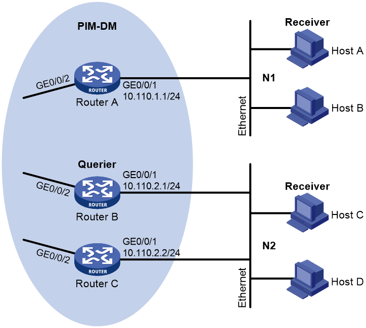
As shown in Figure 1, OSPF and PIM-DM run on the network. VOD streams are sent to receiver hosts in multicast. Receiver hosts of different organizations form stub networks N1 and N2. Host A and Host C are receiver hosts in N1 and N2, respectively. IGMPv2 runs between Router A and N1, and between the other two routers and N2. Router A acts as the IGMP querier in N1. Router B acts as the IGMP querier in N2 because it has a lower IP address. Configure the routers to meet the following requirements:
· The hosts in N1 can join any multicast groups.
· The hosts in N2 can join only multicast group 224.1.1.1.
Analysis
· Configure the same multicast group policy on all routers in N2.
· To control the multicast groups that hosts can join, create a basic ACL and configure a rule to specify a multicast group range.
Software versions used
This configuration example was created and verified on Release 9141P16 of the MSR2630E-X1 router.
Restrictions and guidelines
Because messages vary with different IGMP versions, configure the same IGMP version for all routers on the same subnet for IGMP to work properly.
Procedures
1. Configure the interface IP addresses, unicast routing protocol, and multicast routing protocol for each router in the PIM-DM domain:
# Assign an IP address and subnet mask to each interface. (Details not shown.)
# Configure OSPF for interconnection between the routers. Enable PIM-DM on each router. PIM-DM enables the router to establish multicast forwarding entries, which can be used to forward multicast data from the source to receivers.
2. Configure Router A:
# Enable IP multicast routing, enable PIM-DM on GigabitEthernet 0/0/2, and enable IGMP on GigabitEthernet 0/0/1.
<RouterA> system-view
[RouterA] multicast routing
[RouterA-mrib] quit
[RouterA] interface gigabitethernet 0/0/1
[RouterA-GigabitEthernet0/0/1] igmp enable
[RouterA-GigabitEthernet0/0/1] quit
[RouterA] interface gigabitethernet 0/0/2
[RouterA-GigabitEthernet0/0/2] pim dm
[RouterA-GigabitEthernet0/0/2] quit
3. Configure Router B:
# Enable IP multicast routing, enable PIM-DM on GigabitEthernet 0/0/2, and enable IGMP on GigabitEthernet 0/0/1. Configure a multicast group policy so that the hosts in N2 can join only multicast group 224.1.1.1.
<RouterB> system-view
[RouterB] acl number 2001
[RouterB-acl-basic-2001] rule permit source 224.1.1.1 0
[RouterB-acl-basic-2001] quit
[RouterB] multicast routing
[RouterB-mrib] quit
[RouterB] interface gigabitethernet 0/0/1
[RouterB-GigabitEthernet0/0/1] igmp enable
[RouterB-GigabitEthernet0/0/1] igmp group-policy 2001
[RouterB-GigabitEthernet0/0/1] quit
[RouterB] interface gigabitethernet 0/0/2
[RouterB-GigabitEthernet0/0/2] pim dm
[RouterB-GigabitEthernet0/0/2] quit
4. Configure Router C:
# Enable IP multicast routing, enable PIM-DM on GigabitEthernet 0/0/2, and enable IGMP on GigabitEthernet 0/0/1. Configure a multicast group policy so that the hosts in N2 can join only multicast group 224.1.1.1.
<RouterC> system-view
[RouterC] acl number 2001
[RouterC-acl-basic-2001] rule permit source 224.1.1.1 0
[RouterC-acl-basic-2001] quit
[RouterC] multicast routing
[RouterC-mrib] quit
[RouterC] interface gigabitethernet 0/0/1
[RouterC-GigabitEthernet0/0/1] igmp enable
[RouterC-GigabitEthernet0/0/1] igmp group-policy 2001
[RouterC-GigabitEthernet0/0/1] quit
[RouterC] interface gigabitethernet 0/0/2
[RouterC-GigabitEthernet0/0/2] pim dm
[RouterC-GigabitEthernet0/0/2] quit
Verifying the configuration
After the configuration, send IGMP reports with multicast group address 224.1.1.1 and IGMP reports with multicast group address 224.1.1.2 from Host C (IP address 10.110.2.10) in N2. Use the display igmp group command to display information about IGMP multicast groups on Router B and Router C.
# Display information about IGMP multicast groups on Router B.
[RouterB] display igmp group
IGMP groups in total: 1.
GigabitEthernet0/0/1(10.110.2.1):
IGMP groups reported in total: 1
Group address Last reporter Uptime Expires
224.1.1.1 10.110.2.10 00:02:04 00:01:15
# Display information about IGMP multicast groups on Router C.
[RouterC] display igmp group
IGMP groups in total: 1..
GigabitEthernet0/0/1(10.110.2.2):
IGMP groups reported in total: 1
Group address Last reporter Uptime Expires
224.1.1.1 10.110.2.10 00:02:04 00:01:15
Host C sent IGMP reports with multicast group address 224.1.1.1 and IGMP reports with multicast group address 224.1.1.2. However, only information about multicast group 224.1.1.1 exists on Router B and Router C. This indicates that the multicast group policy has taken effect on Router B and Router C. Multicast receivers in N2 can join only multicast group 224.1.1.1.
Configuration files
· Router A:
#
interface GigabitEthernet0/0/1
port link-mode route
igmp enable
#
interface GigabitEthernet0/0/2
port link-mode route
pim dm
#
multicast routing
#
· Router B:
#
interface GigabitEthernet0/0/1
port link-mode route
igmp enable
igmp group-policy 2001
#
interface GigabitEthernet0/0/2
port link-mode route
pim dm
#
multicast routing
#
acl number 2001
rule 0 permit source 224.1.1.1 0
#
· Router C:
#
interface GigabitEthernet0/0/2
port link-mode route
pim dm
#
interface GigabitEthernet0/0/1
port link-mode route
igmp enable
igmp group-policy 2001
#
multicast routing
#
acl number 2001
rule 0 permit source 224.1.1.1 0
#
Example: Configuring IGMP SSM mapping
Network configuration
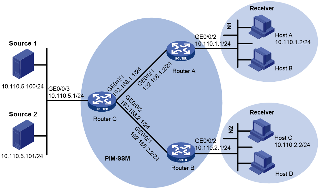
As shown in Figure 2, the PIM-SSM network provides service for SSM group range 232.1.1.0/24. Router A and Router B run IGMPv3. Host A in N1 and Host C in N2 run IGMPv1 or IGMPv2 and do not support IGMPv3. Other hosts run IGMPv3.
Configure the IGMP SSM mapping feature on the routers to meet the following requirements:
· The hosts in N1 can receive multicast packets from only Source 1.
· The hosts in N2 can receive multicast packets from only Source 2.
Software versions used
This configuration example was created and verified on Release 9141P16 of the MSR2630E-X1 router.
Procedures
1. Configure IP addresses and unicast routing protocols:
# Configure IP addresses and subnet masks for interfaces as shown in Figure 2. (Details not shown.)
# Configure OSPF for interconnection between the routers. (Details not shown.)
2. Enable IP multicast routing, and enable PIM-SM on interfaces:
# Enable IP multicast routing on Router A, and enable PIM-SM on GigabitEthernet 0/0/1.
<RouterA> system-view
[RouterA] multicast routing
[RouterA-mrib] quit
[RouterA] interface gigabitethernet 0/0/1
[RouterA-GigabitEthernet0/0/1] pim sm
[RouterA-GigabitEthernet0/0/1] quit
# Configure Router B in the same way Router A is configured. (Details not shown.)
# Enable IP multicast routing on Router C, and enable PIM-SM on each interface.
<RouterC> system-view
[RouterC] multicast routing
[RouterC-mrib] quit
[RouterC] interface gigabitethernet 0/0/1
[RouterC-GigabitEthernet0/0/1] pim sm
[RouterC-GigabitEthernet0/0/1] quit
[RouterC] interface gigabitethernet 0/0/2
[RouterC-GigabitEthernet0/0/2] pim sm
[RouterC-GigabitEthernet0/0/2] quit
[RouterC] interface gigabitethernet 0/0/3
[RouterC-GigabitEthernet0/0/3] pim sm
[RouterC-GigabitEthernet0/0/3] quit
3. Configure a C-BSR and a C-RP on Router C.
[RouterC] pim
[RouterC-pim] c-bsr 192.168.1.1
[RouterC-pim] c-rp 192.168.1.1
[RouterC-pim] quit
4. Enable IGMPv3 on the interfaces connecting to N1 and N2:
# Enable IGMPv3 on GigabitEthernet 0/0/2 of Router A.
[RouterA] interface gigabitethernet 0/0/2
[RouterA-GigabitEthernet0/0/2] igmp enable
[RouterA-GigabitEthernet0/0/2] igmp version 3
[RouterA-GigabitEthernet0/0/2] quit
# Configure Router B in the same way Router A is configured. (Details not shown.)
5. Configure SSM multicast group ranges:
# Configure the SSM group range as 232.1.1.0/24 on Router A.
[RouterA] acl number 2000
[RouterA-acl-basic-2000] rule permit source 232.1.1.0 0.0.0.255
[RouterA-acl-basic-2000] quit
[RouterA] pim
[RouterA-pim] ssm-policy 2000
[RouterA-pim] quit
# Configure Router B and Router C in the same way Router A is configured. (Details not shown.)
6. Configure IGMP SSM mappings:
# Configure an IGMP SSM mapping on Router A so that multicast receivers in N1 can receive multicast packets from only Source 1.
[RouterA] igmp
[RouterA-igmp] ssm-mapping 10.110.5.100 2000
[RouterA-igmp] quit
# Configure an IGMP SSM mapping on Router B so that multicast receivers in N2 can receive multicast packets from only Source 2.
[RouterB] igmp
[RouterB-igmp] ssm-mapping 10.110.5.101 2000
[RouterB-igmp] quit
Verifying the configuration
After the configuration, send IGMPv2 reports with multicast group address 232.1.1.1 from Host A and Host C. Verify the configuration on Router A and Router B.
1. Verify the configuration on Router A:
# View the IGMP SSM mapping for multicast group 232.1.1.1.
[RouterA] display igmp ssm-mapping 232.1.1.1
Group: 232.1.1.1
Source list:
10.110.5.100
# View the PIM routing table information on Router A.
[RouterA] display pim routing-table
Total 0 (*, G) entry; 1 (S, G) entry
(10.110.5.100, 232.1.1.1)
Protocol: pim-ssm, Flag:
UpTime: 00:00:47
Upstream interface: GigabitEthernet0/0/1
Upstream neighbor: 192.168.1.1
RPF prime neighbor: 192.168.1.1
Downstream interface(s) information:
Total number of downstreams: 1
1: GigabitEthernet0/0/2
Protocol: igmp, UpTime: 00:00:47, Expires: -
2. Verify the configuration on Router B:
# View the IGMP SSM mapping for multicast group 232.1.1.1.
[RouterB] display igmp ssm-mapping 232.1.1.1
Group: 232.1.1.1
Source list:
10.110.5.101
# View the PIM routing table information on Router B.
[RouterB] display pim routing-table
Total 0 (*, G) entry; 1 (S, G) entry
(10.110.5.101, 232.1.1.1)
Protocol: pim-ssm, Flag:
UpTime: 00:00:47
Upstream interface: GigabitEthernet0/0/1
Upstream neighbor: 192.168.2.1
RPF prime neighbor: 192.168.2.1
Downstream interface(s) information:
Total number of downstreams: 1
1: GigabitEthernet0/0/2
Protocol: igmp, UpTime: 00:00:47, Expires: -
The output shows that Router A has translated (0.0.0.0, 232.1.1.1) in IGMPv2 reports into (10.110.5.100, 232.1.1.1) and that Router B has translated (0.0.0.0, 232.1.1.1) in IGMPv2 reports into (10.110.5.101, 232.1.1.1). After the translation, Host A can receive multicast packets from only Source 1. Host C can receive multicast packets from only Source 2.
Configuration files
· Router A:
#
interface GigabitEthernet0/0/1
port link-mode route
pim sm
#
interface GigabitEthernet0/0/2
port link-mode route
igmp enable
igmp version 3
#
multicast routing
#
pim
ssm-policy 2000
#
igmp
ssm-mapping 10.110.5.100 2000
#
acl number 2000
rule 0 permit source 232.1.1.0 0.0.0.255
#
· Router B:
#
interface GigabitEthernet0/0/1
port link-mode route
pim sm
#
interface GigabitEthernet0/0/2
port link-mode route
igmp enable
igmp version 3
#
multicast routing
#
pim
ssm-policy 2000
#
igmp
ssm-mapping 10.110.5.100 2000
#
acl number 2000
rule 0 permit source 232.1.1.0 0.0.0.255
#
· Router C:
#
interface GigabitEthernet0/0/1
port link-mode route
pim sm
#
interface GigabitEthernet0/0/2
port link-mode route
pim sm
#
interface GigabitEthernet0/0/3
port link-mode route
pim sm
#
multicast routing
#
pim
c-bsr 192.168.1.1
c-rp 192.168.1.1
#
Example: Configuring IGMP proxying
Network configuration
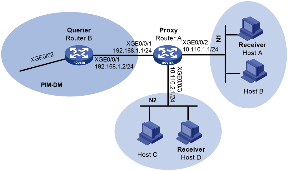
As shown in Figure 3, N1 and N2 are connected to Router B (IGMP querier) in the PIM-DM domain through Router A.
Configure the IGMP proxying feature on Router A so that Router A can forward multicast packets to receivers in N1 and N2 without running PIM-DM.
Analysis
Enable IGMP proxying on the upstream interface of the IGMP proxy, so the IGMP proxy acts as a host for the upstream IGMP querier. Enable IGMP on the downstream interface of the IGMP proxy, so the IGMP proxy acts as an IGMP querier for the downstream receiver hosts.
Software versions used
This configuration example was created and verified on Release 9141P16 of the MSR2630E-X1 router.
Restrictions and guidelines
· Before you enable IGMP proxying, you must enable IP multicast routing.
· If you enable both IGMP proxying and IGMP on the same interface, IGMP does not take effect. On an interface enabled with IGMP proxying, only the igmp version command takes effect and other IGMP commands do not take effect.
· If you enable both IGMP proxying and a multicast routing protocol (such as PIM or MSDP) on the same device, the multicast routing protocol does not take effect.
Procedures
1. Configure IP addresses:
# Configure IP addresses and subnet masks for interfaces as shown in Figure 3. (Details not shown.)
# Configure OSPF for interconnection between the routers in the PIM-DM domain. (Details not shown.)
2. Configure Router A:
# Enable IP multicast routing, and enable IGMP proxying on GigabitEthernet 0/0/1.
<RouterA> system-view
[RouterA] multicast routing
[RouterA-mrib] quit
[RouterA] interface gigabitethernet 0/0/1
[RouterA-GigabitEthernet0/0/1] igmp proxy enable
[RouterA-GigabitEthernet0/0/2] quit
# Enable IGMP on receiver-side interfaces GigabitEthernet 0/0/2 and GigabitEthernet 0/0/3.
[RouterA] interface gigabitethernet 0/0/2
[RouterA-GigabitEthernet0/0/2] igmp enable
[RouterA-GigabitEthernet0/0/2] quit
[RouterA] interface gigabitethernet 0/0/3
[RouterA-GigabitEthernet0/0/3] igmp enable
[RouterA-GigabitEthernet0/0/3] quit
3. Configure Router B:
# Enable IP multicast routing, and enable PIM-DM on GigabitEthernet 0/0/2.
<RouterB> system-view
[RouterB] multicast routing
[RouterB-mrib]quit
[RouterB] interface gigabitethernet 0/0/2
[RouterB-GigabitEthernet0/0/1] pim dm
[RouterB-GigabitEthernet0/0/1] quit
# Enable IGMP on receiver-side interface GigabitEthernet 0/0/1.
[RouterB] interface gigabitethernet 0/0/1
[RouterB-GigabitEthernet0/0/1] igmp enable
[RouterB-GigabitEthernet0/0/1] quit
Verifying the configuration
After the configuration, send IGMP reports with multicast group address 224.1.1.1 from Host A in N1. Use the display igmp group command to display information about IGMP multicast groups on Router A and Router B.
# View information about IGMP multicast groups for GigabitEthernet 0/0/2 on Router A.
[RouterA] display igmp group interface GigabitEthernet0/0/2
GigabitEthernet0/0/2(10.110.1.1):
IGMP groups reported in total: 1
Group address Last reporter Uptime Expires
224.1.1.1 10.110.1.10 00:02:04 00:01:15
# View information about IGMP multicast groups maintained by the IGMP proxy on Router A.
[RouterA] display igmp proxy group
IGMP proxy group records in total: 1
GigabitEthernet0/0/1(192.168.1.1):
IGMP proxy group records in total: 1
Group address Member state Expires
224.1.1.1 Delay 00:00:02
The output shows that GigabitEthernet 0/0/2 on Router A establishes and maintains group memberships after receiving IGMP reports from hosts. For the hosts, the downstream interface on Router A acts as an IGMP querier.
# View information about IGMP multicast groups for GigabitEthernet 0/0/1 on Router B.
[RouterB] display igmp group interface GigabitEthernet0/0/1
GigabitEthernet0/0/1(192.168.1.2):
IGMP groups reported in total: 1
Group address Last reporter Uptime Expires
224.1.1.1 192.168.1.1 00:02:04 00:01:15
The output shows that GigabitEthernet 0/0/1 on Router B establishes and maintains group memberships after receiving IGMP reports from the IGMP proxy. For the upstream IGMP querier (Router B), the upstream interface on Router A acts as a host.
Configuration files
· Router A:
#
interface GigabitEthernet0/0/1
port link-mode route
igmp proxy enable
#
interface GigabitEthernet0/0/2
port link-mode route
igmp enable
#
interface GigabitEthernet0/0/3
port link-mode route
igmp enable
#
multicast routing
#
· Router B:
#
interface GigabitEthernet0/0/1
port link-mode route
igmp enable
#
interface GigabitEthernet0/0/2
port link-mode route
pim dm
#
multicast routing
#
Related documentation
· IP Multicast Configuration Guide in H3C MSR1000[2600][3600] Routers Configuration Guides(V9)
· IP Multicast Command Reference in H3C MSR1000[2600][3600] Routers Command References(V9)