- Table of Contents
-
- H3C MSR1000[2600][3600] Routers Configuration Examples All-in-One-R9141-6W100
- 00-Preface
- 01-Local 802.1X Authentication Configuration Examples
- 02-RADIUS-Based 802.1X Authentication Configuration Examples
- 03-AAA Configuration Examples
- 04-ACL Configuration Examples
- 05-MPLS over ADVPN Configuration Examples
- 06-ARP Attack Protection Configuration Examples
- 07-BFD Configuration Examples
- 08-Basic BGP Configuration Examples
- 09-BGP Route Attribute-Based Route Selection Configuration Examples
- 10-EAA Monitor Policy Configuration Examples
- 11-GRE with OSPF Configuration Examples
- 12-HoVPN Configuration Examples
- 13-IGMP Snooping Configuration Examples
- 14-IGMP Configuration Examples
- 15-IPsec Configuration Examples
- 16-IPsec Digital Certificate Authentication Configuration Examples
- 17-IPv6 IS-IS Configuration Examples
- 18-IPv6 over IPv4 GRE Tunnel Configuration Examples
- 19-IPv6 over IPv4 Manual Tunnel with OSPFv3 Configuration Examples
- 20-IS-IS Configuration Examples
- 21-Combined ISATAP Tunnel and 6to4 Tunnel Configuration Examples
- 22-L2TP over IPsec Configuration Examples
- 23-Multi-Instance L2TP Configuration Examples
- 24-L2TP Multidomain Access Configuration Examples
- 25-MPLS L3VPN Configuration Examples
- 26-MPLS OAM Configuration Examples
- 27-MPLS TE Configuration Examples
- 28-Basic MPLS Configuration Examples
- 29-NAT DNS Mapping Configuration Examples
- 30-NetStream Configuration Examples
- 31-NQA Configuration Examples
- 32-NTP Configuration Examples
- 33-OSPFv3 Configuration Examples
- 34-OSPF Configuration Examples
- 35-OSPF Multi-Process Configuration Examples
- 36-OSPF Multi-Instance Configuration Examples
- 37-Portal Configuration Examples
- 38-PPP Configuration Examples
- 39-RBAC Configuration Examples
- 40-RMON Configuration Examples
- 41-IPv4 NetStream Sampling Configuration Examples
- 42-SNMP Configuration Examples
- 43-SRv6 Configuration Examples
- 44-SSH Configuration Examples
- 45-Tcl Commands Configuration Examples
- 46-VLAN Configuration Examples
- 47-VRRP Configuration Examples
- 48-VXLAN over IPsec Configuration Examples
- 49-WLAN AC Configuration Examples
- 50-Small and Medium-Sized Store Configuration Examples
- 51-Cloudnet VPN Configuration Examples
- 52-Ethernet Link Aggregation Configuration Examples
- 53-Ethernet OAM Configuration Examples
- 54-Outbound Bidirectional NAT Configuration Examples
- 55-NAT Hairpin in C-S Mode Configuration Examples
- 56-Load Sharing NAT Server Configuration Examples
- 57-BIDIR-PIM Configuration Examples
- 58-Control Plane-Based QoS Policy Configuration Examples
- 59-Scheduling a Task Configuration Examples
- 60-Client-Initiated L2TP Tunnel Configuration Examples
- 61-LAC-Auto-Initiated L2TP Tunnel Configuration Examples
- 62-Authorized ARP Configuration Examples
- 63-GTS Configuration Examples
- 64-Traffic Policing Configuration Examples
- 65-Traffic Accounting Configuration Examples
- 66-Mobile Communication Modem Management Configuration Examples
- 67-Port Isolation Configuration Examples
- 68-PBR Configuration Examples
- 69-TFTP Client Software Upgrade Configuration Examples
- 70-FTP Client Software Upgrade Configuration Examples
- 71-FTP Server Software Upgrade Configuration Examples
- 72-Routing Policy Configuration Examples
- 73-Software Upgrade from the BootWare Menu Configuration Examples
- 74-Mirroring Configuration Examples
- Related Documents
-
| Title | Size | Download |
|---|---|---|
| 20-IS-IS Configuration Examples | 182.46 KB |
IS-IS Configuration Examples
Copyright © 2024 New H3C Technologies Co., Ltd. All rights reserved.
No part of this manual may be reproduced or transmitted in any form or by any means without prior written consent of New H3C Technologies Co., Ltd.
Except for the trademarks of New H3C Technologies Co., Ltd., any trademarks that may be mentioned in this document are the property of their respective owners.
The information in this document is subject to change without notice.
Contents
Example: Configuring IS-IS route summarization
Configuring IP addresses for interfaces
Configuring IS-IS route summarization
Introduction
This document provides IS-IS configuration examples.
Prerequisites
The following information applies to Comware 9-based routers. Procedures and information in the examples might be slightly different depending on the software or hardware version of the routers.
The configuration examples were created and verified in a lab environment, and all the devices were started with the factory default configuration. When you are working on a live network, make sure you understand the potential impact of every command on your network.
The following information is provided based on the assumption that you have basic knowledge of IS-IS.
Example: Configuring IS-IS
Network configuration
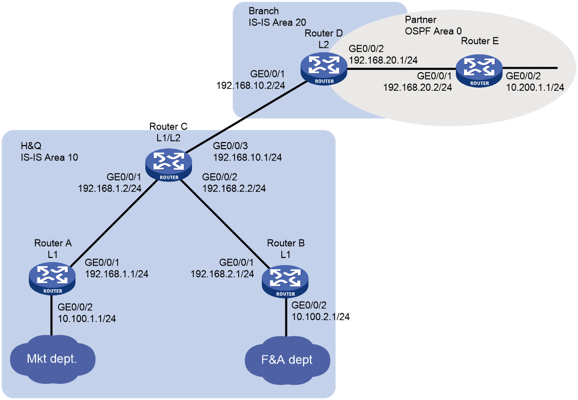
As shown in Figure 1, the company's headquarters and the branch run IS-IS. The partner runs OSPF.
Configure the routers to meet the following requirements:
· The Marketing department can reach the F&A department, the branch, and the partner.
· The F&A department and the branch cannot reach each other, and the branch does not have a route to the F&A department.
· When the IS-IS process on Router C restarts, the communication is not interrupted.
Analysis
To meet the network requirements, you must perform the following tasks:
· To reduce traffic for Router A and Router B, configure them as Level-1 routers to allow communication only between the Marketing department and the F&A department.
· Configure Router C to use a prefix list to advertise only network 10.100.1.0/24 to Level-2 to ensure that the branch does not have a route to the F&A department.
· Configure route redistribution between IS-IS and OSPF on Router D to allow communication between the Marketing department and the partner.
· Enable IS-IS Graceful Restart (GR) on Router C to ensure that the communication is not interrupted when the IS-IS process on Router C restarts.
Software versions used
This configuration example was created and verified on R9141P16 of the MSR2630E-X1 device.
Restrictions and guidelines
To avoid blackhole routes, do not change the network topology during the IS-IS GR process.
Procedures
Configuring Router A
# Configure an IP address for GigabitEthernet 1/0/1.
<RouterA> system-view
[RouterA] interface gigabitethernet 1/0/1
[RouterA-GigabitEthernet1/0/1] ip address 192.168.1.1 24
[RouterA-GigabitEthernet1/0/1] quit
# Configure IP addresses for other interfaces, as shown in Figure 1. (Details not shown.)
# Configure IS-IS.
[RouterA] isis 1
[RouterA-isis-1] is-level level-1
[RouterA-isis-1] network-entity 10.1921.6800.1001.00
[RouterA-isis-1] quit
[RouterA] interface gigabitethernet 1/0/1
[RouterA–GigabitEthernet1/0/1] isis enable 1
[RouterA–GigabitEthernet1/0/1] quit
[RouterA] interface gigabitethernet 1/0/2
[RouterA–GigabitEthernet1/0/2] isis enable 1
[RouterA–GigabitEthernet1/0/2] quit
Configuring Router B
# Configure an IP address for GigabitEthernet 1/0/1.
<RouterB> system-view
[RouterB] interface gigabitethernet 1/0/1
[RouterB-GigabitEthernet1/0/1] ip address 192.168.2.1 24
[RouterB-GigabitEthernet1/0/1] quit
# Configure IP addresses for other interfaces, as shown in Figure 1. (Details not shown.)
# Configure IS-IS.
[RouterB] isis 1
[RouterB-isis-1] is-level level-1
[RouterB-isis-1] network-entity 10.1921.6800.2001.00
[RouterB-isis-1] quit
[RouterB] interface gigabitethernet 1/0/1
[RouterB–GigabitEthernet1/0/1] isis enable 1
[RouterB–GigabitEthernet1/0/1] quit
[RouterB] interface gigabitethernet 1/0/2
[RouterB–GigabitEthernet1/0/2] isis enable 1
[RouterB–GigabitEthernet1/0/2] quit
Configuring Router C
# Configure an IP address for GigabitEthernet 1/0/1.
<RouterC> system-view
[RouterC] interface gigabitethernet 1/0/1
[RouterC-GigabitEthernet1/0/1] ip address 192.168.1.2 24
[RouterC-GigabitEthernet1/0/1] quit
# Configure IP addresses for other interfaces, as shown in Figure 1. (Details not shown.)
# Configure IS-IS.
[RouterC-isis-1] network-entity 10.1921.6801.0001.00
[RouterC-isis-1] quit
[RouterC] interface gigabitethernet 1/0/1
[RouterC–GigabitEthernet1/0/1] isis enable 1
[RouterC–GigabitEthernet1/0/1] quit
[RouterC] interface gigabitethernet 1/0/2
[RouterC–GigabitEthernet1/0/2] isis enable 1
[RouterC–GigabitEthernet1/0/2] quit
[RouterC] interface gigabitethernet 1/0/3
[RouterC–GigabitEthernet1/0/3] isis enable 1
[RouterC–GigabitEthernet1/0/3] quit
# Configure route leaking from Level-1 to Level-2, and use prefix list 1 to advertise only network 10.100.1.0/24 to Level-2.
[RouterC] ip prefix-list 1 permit 10.100.1.0 24
[RouterC] isis 1
[RouterC-isis-1] address-family ipv4
[RouterC-isis-1-ipv4] import-route isis level-1 into level-2 filter-policy prefix-list 1
[RouterC-isis-1-ipv4] quit
# Enable IS-IS GR.
[RouterC -isis-1] graceful-restart
[RouterC -isis-1] quit
Configuring Router D
# Configure an IP address for GigabitEthernet 1/0/1.
<RouterD> system-view
[RouterD] interface gigabitethernet 1/0/1
[RouterD-GigabitEthernet1/0/1] ip address 192.168.10.2 24
[RouterD-GigabitEthernet1/0/1] quit
# Configure IP addresses for other interfaces, as shown in Figure 1. (Details not shown.)
# Configure IS-IS.
[RouterD] isis 1
[RouterD-isis-1] is-level level-2
[RouterD-isis-1] network-entity 20.1921.6802.0001.00
[RouterD-isis-1] quit
[RouterD] interface gigabitethernet 1/0/1
[RouterD–GigabitEthernet1/0/1] isis enable 1
[RouterD–GigabitEthernet1/0/1] quit
[RouterD] interface gigabitethernet 1/0/2
[RouterD–GigabitEthernet1/0/2] isis enable 1
[RouterD–GigabitEthernet1/0/2] quit
# Configure OSPF.
[RouterD] ospf
[RouterD-ospf-1] area 0
[RouterD-ospf-1-area-0.0.0.0] network 192.168.20.0 0.0.0.255
[RouterD-ospf-1-area-0.0.0.0] quit
[RouterD-ospf-1] quit
# Redistribute OSPF and direct routes into IS-IS.
[RouterD] isis 1
[RouterD-isis-1] address-family ipv4
[RouterD-isis-1-ipv4] import-route ospf
[RouterD-isis-1-ipv4] import-route direct
[RouterD-isis-1-ipv4] quit
[RouterD-isis-1] quit
# Redistribute IS-IS and direct routes into OSPF.
[RouterD] ospf 1
[RouterD-ospf-1] import-route isis 1
[RouterD-ospf-1] import-route direct
Configuring Router E
# Configure an IP address for GigabitEthernet 1/0/1.
<RouterE> system-view
[RouterE] interface gigabitethernet 1/0/1
[RouterE-GigabitEthernet1/0/1] ip address 192.168.20.2 24
[RouterE-GigabitEthernet1/0/1] quit
# Configure IP addresses for other interfaces, as shown in Figure 1. (Details not shown.)
# Configure OSPF.
[RouterE] ospf
[RouterE-ospf-1] area 0
[RouterE-ospf-1-area-0.0.0.0] network 192.168.20.0 0.0.0.255
[RouterE-ospf-1-area-0.0.0.0] network 10.200.1.0 0.0.0.255
[RouterE-ospf-1-area-0.0.0.0] quit
[RouterE-ospf-1] quit
Verifying the configuration
# View the IS-IS routing table on Router D and verify that the branch can reach the Marketing department, but cannot reach the F&A department.
[RouterD] display isis route
Route information for IS-IS(1)
------------------------------
Level-2 IPv4 Forwarding Table
-----------------------------
IPv4 Destination IntCost ExtCost ExitInterface NextHop Flags
-------------------------------------------------------------------------------
192.168.10.0/24 10 NULL GE1/0/1 Direct D/L/-
192.168.1.0/24 20 NULL GE1/0/1 192.168.10.1 R/-/-
10.100.1.0/24 30 NULL GE1/0/1 192.168.10.1 R/-/-
192.168.2.0/24 20 NULL GE1/0/1 192.168.10.1 R/-/-
192.168.20.0/24 10 NULL GE1/0/2 Direct D/L/-
Flags: D-Direct, R-Added to Rib, L-Advertised in LSPs, U-Up/Down Bit Set
# Verify that the company can communicate with the partner.
· Display the IS-IS routing table on Router C.
[RouterC] display isis route
Route information for IS-IS(1)
------------------------------
Level-1 IPv4 Forwarding Table
-----------------------------
IPv4 Destination IntCost ExtCost ExitInterface NextHop Flags
-------------------------------------------------------------------------------
192.168.10.0/24 10 NULL GE1/0/3 Direct D/L/-
192.168.1.0/24 10 NULL GE1/0/1 Direct D/L/-
10.100.1.0/24 20 NULL GE1/0/1 192.168.1.1 R/L/-
10.100.2.0/24 20 NULL GE1/0/2 192.168.2.1 R/-/-
192.168.2.0/24 10 NULL GE1/0/2 Direct D/L/-
Flags: D-Direct, R-Added to Rib, L-Advertised in LSPs, U-Up/Down Bit Set
Level-2 IPv4 Forwarding Table
-----------------------------
IPv4 Destination IntCost ExtCost ExitInterface NextHop Flags
-------------------------------------------------------------------------------
192.168.10.0/24 10 NULL GE1/0/3 Direct D/L/-
10.200.1.0/24 10 0 GE1/0/3 192.168.10.2 R/-/-
192.168.20.0/24 10 0 GE1/0/3 192.168.10.2 R/-/-
192.168.1.0/24 10 NULL GE1/0/1 Direct D/L/-
192.168.2.0/24 10 NULL GE1/0/2 Direct D/L/-
Flags: D-Direct, R-Added to Rib, L-Advertised in LSPs, U-Up/Down Bit Set
· Ping 10.200.1.1 from Router C.
[RouterC] ping 10.200.1.1
Ping 10.200.1.1 (10.200.1.1): 56 data bytes, press CTRL_C to break
56 bytes from 10.200.1.1: icmp_seq=0 ttl=254 time=1.862 ms
56 bytes from 10.200.1.1: icmp_seq=1 ttl=254 time=2.969 ms
56 bytes from 10.200.1.1: icmp_seq=2 ttl=254 time=1.402 ms
56 bytes from 10.200.1.1: icmp_seq=3 ttl=254 time=1.324 ms
56 bytes from 10.200.1.1: icmp_seq=4 ttl=254 time=1.510 ms
--- Ping statistics for 10.200.1.1 ---
5 packet(s) transmitted, 5 packet(s) received, 0.0% packet loss
round-trip min/avg/max/std-dev = 1.324/1.813/2.969/0.606 ms
# Verify that the communication is not interrupted when the IS-IS process restarts.
· Ping Router B from Router A.
[RouterA] ping -c 10000 10.100.2.1
Ping 10.100.2.1 (10.100.2.1): 56 data bytes, press CTRL_C to break
56 bytes from 10.100.2.1: icmp_seq=0 ttl=254 time=1.185 ms
56 bytes from 10.100.2.1: icmp_seq=1 ttl=254 time=1.087 ms
……
· Restart the IS-IS process on Router C.
[RouterC] quit
<RouterC> reset isis all graceful-restart
Reset IS-IS process? [Y/N] :y
# Ping Router B from Router A and verify that the communication is not interrupted when the IS-IS process restarts.
[RouterA] ping -c 10000 10.100.2.1
Ping 10.100.2.1 (10.100.2.1): 56 data bytes, press CTRL_C to break
56 bytes from 10.100.2.1: icmp_seq=0 ttl=254 time=1.185 ms
56 bytes from 10.100.2.1: icmp_seq=1 ttl=254 time=1.087 ms
56 bytes from 13.13.13.3: icmp_seq=2 ttl=254 time=1.672 ms
56 bytes from 13.13.13.3: icmp_seq=3 ttl=254 time=1.751 ms
56 bytes from 13.13.13.3: icmp_seq=4 ttl=254 time=1.816 ms
56 bytes from 13.13.13.3: icmp_seq=5 ttl=254 time=1.814 ms
# Check the IS-IS GR state on Router C.
<RouterC> display isis graceful-restart status
Restart information for IS-IS(1)
--------------------------------
Restart status: COMPLETE
Restart phase: Finish
Restart t1: 3, count 10; Restart t2: 60; Restart t3: 300
SA Bit: supported
Level-1 restart information
---------------------------
Total number of interfaces: 3
Number of waiting LSPs: 0
Level-2 restart information
---------------------------
Total number of interfaces: 3
Number of waiting LSPs: 0
Configuration files
Router A
isis 1
is-level level-1
network-entity 10.1921.6800.1001.00
#
interface GigabitEthernet1/0/1
ip address 192.168.1.1 255.255.255.0
isis enable 1
#
interface GigabitEthernet1/0/2
ip address 10.100.1.1 255.255.255.0
isis enable 1
#
Router B
#
isis 1
is-level level-1
network-entity 10.1921.6800.2001.00
#
interface GigabitEthernet1/0/1
ip address 192.168.2.1 255.255.255.0
isis enable 1
#
interface GigabitEthernet1/0/2
ip address 10.100.2.1 255.255.255.0
isis enable 1
#
Router C
isis 1
graceful-restart
network-entity 10.1921.6801.0001.00
#
address-family ipv4 unicast
import-route isis level-1 into level-2 filter-policy prefix-list 1
#
interface GigabitEthernet1/0/1
ip address 192.168.1.2 255.255.255.0
isis enable 1
#
interface GigabitEthernet1/0/2
ip address 192.168.2.2 255.255.255.0
isis enable 1
#
interface GigabitEthernet1/0/3
ip address 192.168.10.1 255.255.255.0
isis enable 1
#
ip prefix-list 1 index 10 permit 10.100.1.0 24
#
Router D
#
isis 1
is-level level-2
network-entity 20.1921.6802.0001.00
#
address-family ipv4 unicast
import-route direct
import-route ospf 1
#
ospf 1
import-route direct
import-route isis 1
area 0.0.0.0
network 192.168.20.0 0.0.0.255
#
interface GigabitEthernet1/0/1
ip address 192.168.10.2 255.255.255.0
isis enable 1
#
interface GigabitEthernet1/0/2
ip address 192.168.20.1 255.255.255.0
#
Router E
#
ospf 1
area 0.0.0.0
network 10.200.1.0 0.0.0.255
network 192.168.20.0 0.0.0.255
#
interface GigabitEthernet1/0/1
ip address 192.168.20.2 255.255.255.0
#
interface GigabitEthernet1/0/2
ip address 10.200.1.1 255.255.255.0
#
Example: Configuring IS-IS route summarization
Network configuration
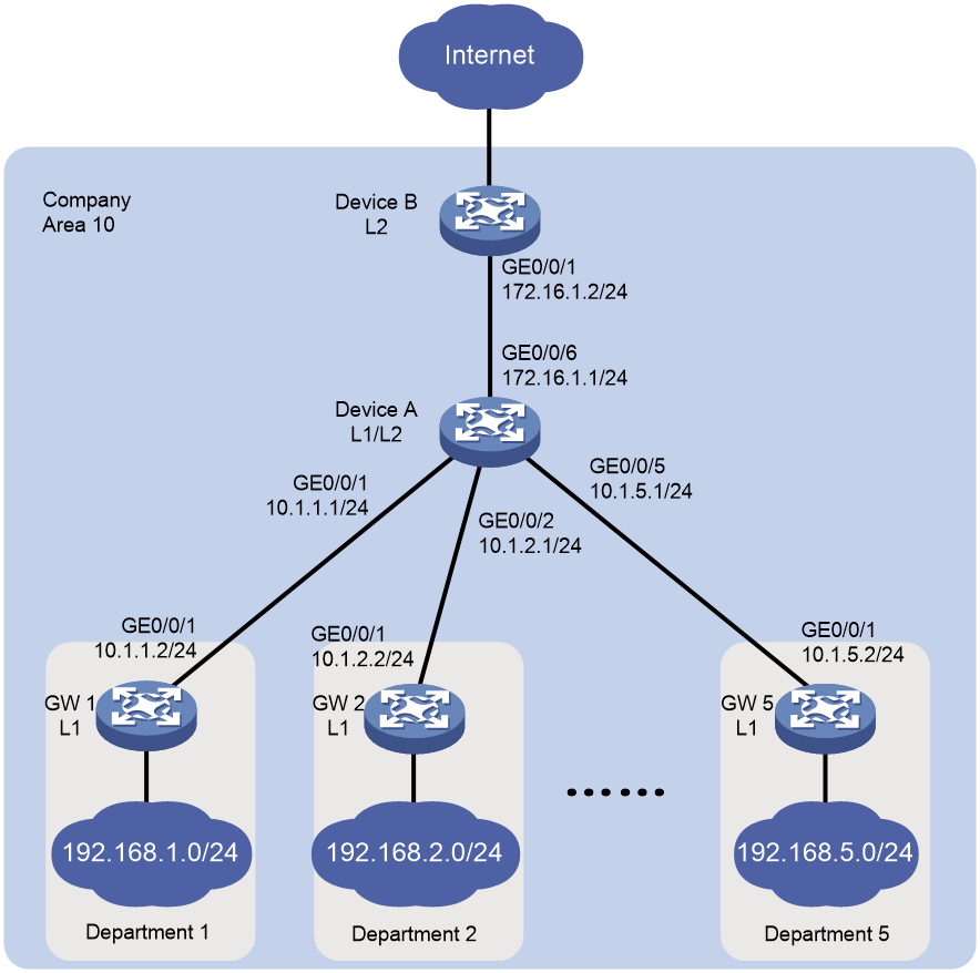
As shown in Figure 2, the five departments of a company use IS-IS to connect to the backbone network. The five departments are assigned the networks 192.168.1.0/24, 192.168.2.0/24, 192.168.3.0/24, 192.168.4.0/24, and 192.168.5.0/24, respectively. Configure IS-IS route summarization to reduce routing entries and save system resources for Device B.
Analysis
Configure route summarization on Device A, because route summarization applies only to locally generated LSPs.
To avoid blackhole routes, set the summary route to 192.168.0.0/21.
Software versions used
This configuration example was created and verified on R9141P16 of the MSR2630E-X1 device.
Procedures
Configuring IP addresses for interfaces
# Configure an IP address for GigabitEthernet 1/0/6 on Device A.
<DeviceA> system-view
[DeviceA] interface gigabitethernet 1/0/6
[DeviceA-GigabitEthernet1/0/6] ip address 172.16.1.1 24
[DeviceA-GigabitEthernet1/0/6] quit
# Configure IP addresses for other interfaces as shown in Figure 2 in the same way GigabitEthernet 1/0/6 is configured. (Details not shown.)
Configuring basic IS-IS
Configuring Device A
# Enable IS-IS on Device A and configure Device A as a Level-1-2 router.
[DeviceA] isis 1
[DeviceA-isis-1] network-entity 10.0000.0000.0001.00
[DeviceA-isis-1] is-level level-1-2
[DeviceA-isis-1] quit
# Enable IS-IS on GigabitEthernet 1/0/1.
[DeviceA] interface gigabitethernet 1/0/1
[DeviceA–GigabitEthernet1/0/1] isis enable 1
[DeviceA–GigabitEthernet1/0/1] quit
# Configure other interfaces in the same way GigabitEthernet 1/0/1 is configured. (Details not shown.)
Configuring Device B
# Enable IS-IS on Device B and configure Device B as a Level-2 router.
[DeviceB] isis 1
[DeviceB-isis-1] network-entity 10.0000.0000.0002.00
[DeviceB-isis-1] is-level level-2
[DeviceB-isis-1] quit
# Enable IS-IS on GigabitEthernet 1/0/1.
[DeviceB] interface gigabitethernet 1/0/1
[DeviceB–GigabitEthernet1/0/1] isis enable 1
[DeviceB–GigabitEthernet1/0/1] quit
Configuring the gateways
# Enable IS-IS on GW 1 and configure GW 1 as a Level-1 router.
[GW1] isis 1
[GW1-isis-1] network-entity 10.0001.0001.0001.00
[GW1-isis-1] is-level level-1
[GW1-isis-1] quit
# Enable IS-IS on GigabitEthernet 1/0/1.
[GW1] interface gigabitethernet 1/0/1
[GW1–GigabitEthernet1/0/1] isis enable 1
[GW1–GigabitEthernet1/0/1] quit
# Configure other gateways in the same way GW 1 is configured. (Details not shown.)
Displaying IS-IS routing information on Device B
# Display IS-IS routing information on Device B to view the network address of each department.
[DeviceB] display isis route
Route information for IS-IS(1)
------------------------------
Level-2 IPv4 Forwarding Table
-----------------------------
IPv4 Destination IntCost ExtCost ExitInterface NextHop Flags
-------------------------------------------------------------------------------
192.168.1.0/24 30 NULL GE1/0/1 172.16.1.1 R/-/-
10.1.1.0/24 20 NULL GE1/0/1 172.16.1.1 R/-/-
192.168.2.0/24 30 NULL GE1/0/1 172.16.1.1 R/-/-
10.1.2.0/24 20 NULL GE1/0/1 172.16.1.1 R/-/-
192.168.3.0/24 30 NULL GE1/0/1 172.16.1.1 R/-/-
10.1.3.0/24 20 NULL GE1/0/1 172.16.1.1 R/-/-
192.168.4.0/24 30 NULL GE1/0/1 172.16.1.1 R/-/-
10.1.4.0/24 20 NULL GE1/0/1 172.16.1.1 R/-/-
192.168.5.0/24 30 NULL GE1/0/1 172.16.1.1 R/-/-
10.1.5.0/24 20 NULL GE1/0/1 172.16.1.1 R/-/-
172.16.1.0/24 10 NULL GE1/0/1 Direct D/L/-
Flags: D-Direct, R-Added to Rib, L-Advertised in LSPs, U-Up/Down Bit Set
Configuring IS-IS route summarization
# Configure IS-IS route summarization on Device A.
[DeviceA] isis 1
[DeviceA-isis-1] address-family ipv4
[DeviceA-isis-1-ipv4] summary 192.168.0.0 21
Verifying the configuration
# Display IS-IS routing information on Device B.
[DeviceB] display isis route
Route information for IS-IS(1)
------------------------------
Level-2 IPv4 Forwarding Table
-----------------------------
IPv4 Destination IntCost ExtCost ExitInterface NextHop Flags
-------------------------------------------------------------------------------
10.1.1.0/24 20 NULL GE1/0/1 172.16.1.1 R/-/-
10.1.2.0/24 20 NULL GE1/0/1 172.16.1.1 R/-/-
10.1.3.0/24 20 NULL GE1/0/1 172.16.1.1 R/-/-
10.1.4.0/24 20 NULL GE1/0/1 172.16.1.1 R/-/-
10.1.5.0/24 20 NULL GE1/0/1 172.16.1.1 R/-/-
172.16.1.0/24 10 NULL GE1/0/1 Direct D/L/-
192.168.0.0/21 30 NULL GE1/0/1 172.16.1.1 R/-/-
Flags: D-Direct, R-Added to Rib, L-Advertised in LSPs, U-Up/Down Bit Set
The output shows that the networks have been summarized into a single network 192.168.0.0/21.
Configuration files
Device A
#
isis 1
network-entity 10.0000.0000.0001.00
#
address-family ipv4
summary 192.168.0.0 255.255.248.0
#
interface GigabitEthernet1/0/1
port link-mode route
ip address 10.1.1.1 255.255.255.0
isis enable 1
#
interface GigabitEthernet1/0/2
port link-mode route
ip address 10.1.2.1 255.255.255.0
isis enable 1
#
interface GigabitEthernet1/0/3
port link-mode route
ip address 10.1.3.1 255.255.255.0
isis enable 1
#
interface GigabitEthernet1/0/4
port link-mode route
ip address 10.1.4.1 255.255.255.0
isis enable 1
#
interface GigabitEthernet1/0/5
port link-mode route
ip address 10.1.5.1 255.255.255.0
isis enable 1
#
interface GigabitEthernet1/0/7
port link-mode route
ip address 172.16.1.1 255.255.255.0
isis enable 1
#
Device B
#
isis 1
is-level level-2
network-entity 10.0000.0000.0002.00
#
interface GigabitEthernet1/0/1
port link-mode route
ip address 172.16.1.2 255.255.255.0
isis enable 1
#
GW 1
#
isis 1
is-level level-1
network-entity 10.0001.0001.0001.00
#
interface GigabitEthernet1/0/1
port link-mode route
ip address 10.1.1.2 255.255.255.0
isis enable 1
#
interface GigabitEthernet1/0/2
port link-mode route
ip address 192.168.1.1 255.255.255.0
isis enable 1
#
Other gateways
The configuration files for other gateways are similar to the configuration file for GW 1. (Details not shown.)
Related documentation
· Layer 3—IP Routing Configuration Guide in H3C MSR1000[2600][3600] Routers Configuration Guides(V9)
· Layer 3—IP Routing Command Reference in H3C MSR1000[2600][3600] Routers Command References(V9)