- Table of Contents
-
- H3C MSR1000[2600][3600] Routers Configuration Examples All-in-One-R9141-6W100
- 00-Preface
- 01-Local 802.1X Authentication Configuration Examples
- 02-RADIUS-Based 802.1X Authentication Configuration Examples
- 03-AAA Configuration Examples
- 04-ACL Configuration Examples
- 05-MPLS over ADVPN Configuration Examples
- 06-ARP Attack Protection Configuration Examples
- 07-BFD Configuration Examples
- 08-Basic BGP Configuration Examples
- 09-BGP Route Attribute-Based Route Selection Configuration Examples
- 10-EAA Monitor Policy Configuration Examples
- 11-GRE with OSPF Configuration Examples
- 12-HoVPN Configuration Examples
- 13-IGMP Snooping Configuration Examples
- 14-IGMP Configuration Examples
- 15-IPsec Configuration Examples
- 16-IPsec Digital Certificate Authentication Configuration Examples
- 17-IPv6 IS-IS Configuration Examples
- 18-IPv6 over IPv4 GRE Tunnel Configuration Examples
- 19-IPv6 over IPv4 Manual Tunnel with OSPFv3 Configuration Examples
- 20-IS-IS Configuration Examples
- 21-Combined ISATAP Tunnel and 6to4 Tunnel Configuration Examples
- 22-L2TP over IPsec Configuration Examples
- 23-Multi-Instance L2TP Configuration Examples
- 24-L2TP Multidomain Access Configuration Examples
- 25-MPLS L3VPN Configuration Examples
- 26-MPLS OAM Configuration Examples
- 27-MPLS TE Configuration Examples
- 28-Basic MPLS Configuration Examples
- 29-NAT DNS Mapping Configuration Examples
- 30-NetStream Configuration Examples
- 31-NQA Configuration Examples
- 32-NTP Configuration Examples
- 33-OSPFv3 Configuration Examples
- 34-OSPF Configuration Examples
- 35-OSPF Multi-Process Configuration Examples
- 36-OSPF Multi-Instance Configuration Examples
- 37-Portal Configuration Examples
- 38-PPP Configuration Examples
- 39-RBAC Configuration Examples
- 40-RMON Configuration Examples
- 41-IPv4 NetStream Sampling Configuration Examples
- 42-SNMP Configuration Examples
- 43-SRv6 Configuration Examples
- 44-SSH Configuration Examples
- 45-Tcl Commands Configuration Examples
- 46-VLAN Configuration Examples
- 47-VRRP Configuration Examples
- 48-VXLAN over IPsec Configuration Examples
- 49-WLAN AC Configuration Examples
- 50-Small and Medium-Sized Store Configuration Examples
- 51-Cloudnet VPN Configuration Examples
- 52-Ethernet Link Aggregation Configuration Examples
- 53-Ethernet OAM Configuration Examples
- 54-Outbound Bidirectional NAT Configuration Examples
- 55-NAT Hairpin in C-S Mode Configuration Examples
- 56-Load Sharing NAT Server Configuration Examples
- 57-BIDIR-PIM Configuration Examples
- 58-Control Plane-Based QoS Policy Configuration Examples
- 59-Scheduling a Task Configuration Examples
- 60-Client-Initiated L2TP Tunnel Configuration Examples
- 61-LAC-Auto-Initiated L2TP Tunnel Configuration Examples
- 62-Authorized ARP Configuration Examples
- 63-GTS Configuration Examples
- 64-Traffic Policing Configuration Examples
- 65-Traffic Accounting Configuration Examples
- 66-Mobile Communication Modem Management Configuration Examples
- 67-Port Isolation Configuration Examples
- 68-PBR Configuration Examples
- 69-TFTP Client Software Upgrade Configuration Examples
- 70-FTP Client Software Upgrade Configuration Examples
- 71-FTP Server Software Upgrade Configuration Examples
- 72-Routing Policy Configuration Examples
- 73-Software Upgrade from the BootWare Menu Configuration Examples
- 74-Mirroring Configuration Examples
- Related Documents
-
| Title | Size | Download |
|---|---|---|
| 56-Load Sharing NAT Server Configuration Examples | 82.88 KB |
Load Sharing NAT Server Configuration Examples
Copyright © 2024 New H3C Technologies Co., Ltd. All rights reserved.
No part of this manual may be reproduced or transmitted in any form or by any means without prior written consent of New H3C Technologies Co., Ltd.
Except for the trademarks of New H3C Technologies Co., Ltd., any trademarks that may be mentioned in this document are the property of their respective owners.
The information in this document is subject to change without notice.
Introduction
This document provides load sharing NAT server configuration examples.
Prerequisites
This document applies to Comware 9-based routers. Procedures and information in the examples might be slightly different depending on the software or hardware version of the routers.
The configuration examples in this document were created and verified in a lab environment, and all the devices were started with the factory default configuration. When you are working on a live network, make sure you understand the potential impact of every command on your network.
This document assumes that you have basic knowledge of NAT.
Example: Configuring load sharing NAT server
Network configuration
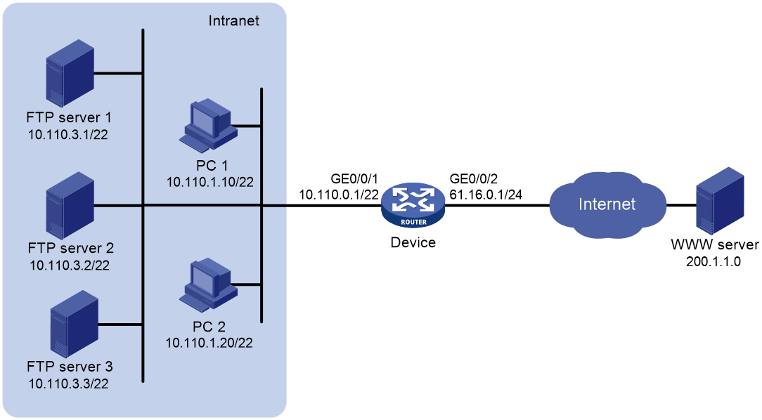
As shown in Figure 1, the internal network address is 10.110.0.0/22. The company has three public IP addresses 61.16.0.1 to 61.16.0.3. Internal users use IP addresses 10.110.0.0 to 10.110.2.255. Three FTP servers in the intranet use IP addresses 10.110.3.1 to 10.110.3.3 to provide FTP services.
Configure the network to meet the following requirements:
· Internal users use public IP addresses 61.16.0.2 and 61.16.0.3 to access the Internet.
· External and internal hosts use IP address 61.16.0.1 to access the FTP servers in the intranet.
· Three FTP servers implement load sharing but cannot initiate connections to the external network.
Analysis
· For internal users to access the Internet, configure an ACL to identify packets from subnets 10.110.0.0 to 10.110.2.255, and configure PAT to translate these private addresses to public addresses 61.16.0.2 and 61.16.0.3.
· For three FTP servers to provide services at the same time, configure a NAT server group to implement load sharing.
· For internal users to access FTP servers by using IP address 61.16.0.1, enable NAT hairpin on GigabitEthernet 0/0/1 of the device.
Software versions used
This configuration example was created and verified on R9141P16 of the MSR2630E-X1 device.
Restrictions and guidelines
To enable NAT hairpin, make sure all of the interfaces configured in the nat server, nat outbound, and nat hairpin commands are on the same interface module.
Procedures
Configuring IP addresses for interfaces on the device
# Configure IP addresses for GigabitEthernet 0/0/1 and GigabitEthernet 0/0/2.
<Device> system-view
[Device] interface gigabitethernet 0/0/1
[Device-GigabitEthernet0/0/1] ip address 10.110.0.1 255.255.252.0
[Device-GigabitEthernet0/0/1] quit
[Device] interface gigabitethernet 0/0/2
[Device-GigabitEthernet0/0/2] ip address 61.16.0.1 255.255.255.0
[Device-GigabitEthernet0/0/2] quit
Configuring internal users to access the external network
# Configure address group 0, and add public IP addresses 61.16.0.2 and 61.16.0.3 to the group.
[Device-nat-address-group-0] address 61.16.0.2 61.16.0.3
[Device-nat-address-group-0] quit
# Configure ACL 2000 to identify packets from subnets 10.110.0.0 to 10.110.2.255.
[Device-acl-ipv4-basic-2000] rule permit source 10.110.0.0 0.0.1.255
[Device-acl-ipv4-basic-2000] rule permit source 10.110.2.0 0.0.0.255
[Device-acl-ipv4-basic-2000] quit
# Enable outbound dynamic PAT on GigabitEthernet 0/0/2 to translate the source IP addresses of the packets permitted by the ACL into the IP addresses in address group 0.
[Device] interface gigabitethernet 0/0/2
[Device-GigabitEthernet0/0/2] nat outbound 2000 address-group 0
[Device-GigabitEthernet0/0/2] quit
Configuring FTP servers to provide FTP services
# Create NAT server group 0, and add members 10.110.3.1, 10.110.3.2, and 10.110.3.3 to the group.
[Device-server-group-0] inside ip 10.110.3.1 port 21
[Device-server-group-0] inside ip 10.110.3.2 port 21
[Device-server-group-0] inside ip 10.110.3.3 port 21
[Device-server-group-0] quit
# Associate NAT server group 0 with GigabitEthernet 0/0/2 so that servers in the server group can provide FTP services.
[Device] interface gigabitethernet 0/0/2
[Device-GigabitEthernet0/0/2] nat server protocol tcp global 61.16.0.1 ftp inside server-group 0
[Device-GigabitEthernet0/0/2] quit
# Enable NAT hairpin on GigabitEthernet 0/0/1.
[Device] interface gigabitethernet 1/0/1
[Device-GigabitEthernet0/0/1] nat hairpin enable
[Device-GigabitEthernet0/0/1] quit
Verifying the configuration
# Display NAT sessions that are generated when PC 1 accesses the WWW server.
[Device] display nat session verbose
Slot 1:
Initiator:
Source IP/port: 10.110.1.10/1024
Destination IP/port: 200.1.1.10/80
DS-Lite tunnel peer: -
VPN instance/VLAN ID/VLL ID: -/-/-
Protocol: UDP(17)
Inbound interface: GigabitEthernet0/0/1
Responder:
Source IP/port: 200.1.1.10/80
Destination IP/port: 61.16.0.2/1025
DS-Lite tunnel peer: -
VPN instance/VLAN ID/VLL ID: -/-/-
Protocol: UDP(17)
Inbound interface: GigabitEthernet0/0/2
State: UDP_READY
Application: HTTP
Rule ID: -/-/-
Rule name:
Start time: 2014-07-08 13:30:47 TTL: 60s
Initiator->Responder: 21946552 packets 2414120720 bytes
Responder->Initiator: 650389 packets 71542790 bytes
Total sessions found: 1
# Display NAT sessions that are generated when two external users (61.16.0.10 and 61.16.0.11) access the FTP servers at the same time. The output shows that two NAT sessions are generated, and FTP server 1 and FTP server 2 provide FTP services for the two users respectively.
[Device] display nat session verbose
Slot 1:
Initiator:
Source IP/port: 61.16.0.11/1024
Destination IP/port: 61.16.0.1/21
DS-Lite tunnel peer: -
VPN instance/VLAN ID/VLL ID: -/-/-
Protocol: TCP(6)
Inbound interface: GigabitEthernet0/0/2
Responder:
Source IP/port: 10.110.3.1/21
Destination IP/port: 61.16.0.11/1024
DS-Lite tunnel peer: -
VPN instance/VLAN ID/VLL ID: -/-/-
Protocol: TCP(6)
Inbound interface: GigabitEthernet0/0/1
State: TCP_ESTABLISHED
Application: FTP
Rule ID: -/-/-
Rule name:
Start time: 2014-07-08 14:11:41 TTL: 3600s
Initiator->Responder: 598098 packets 65790780 bytes
Responder->Initiator: 0 packets 0 bytes
Initiator:
Source IP/port: 61.16.0.10/1024
Destination IP/port: 61.16.0.1/21
DS-Lite tunnel peer: -
VPN instance/VLAN ID/VLL ID: -/-/-
Protocol: TCP(6)
Inbound interface: GigabitEthernet0/0/2
Responder:
Source IP/port: 10.110.3.2/21
Destination IP/port: 61.16.0.10/1024
DS-Lite tunnel peer: -
VPN instance/VLAN ID/VLL ID: -/-/-
Protocol: TCP(6)
Inbound interface: GigabitEthernet0/0/1
State: TCP_ESTABLISHED
Application: FTP
Rule ID: -/-/-
Rule name:
Start time: 2014-07-08 14:12:00 TTL: 3600s
Initiator->Responder: 74783 packets 8226130 bytes
Responder->Initiator: 0 packets 0 bytes
Total sessions found: 2
# Display NAT sessions that are generated when PC 1 accesses the FTP servers by using IP address 61.16.0.1.
[Device] display nat session verbose
Slot 1:
Initiator:
Source IP/port: 10.110.1.10/1024
Destination IP/port: 61.16.0.1/21
DS-Lite tunnel peer: -
VPN instance/VLAN ID/VLL ID: -/-/-
Protocol: TCP(6)
Inbound interface: GigabitEthernet0/0/1
Responder:
Source IP/port: 10.110.3.1/21
Destination IP/port: 61.16.0.2/1025
DS-Lite tunnel peer: -
VPN instance/VLAN ID/VLL ID: -/-/-
Protocol: TCP(6)
Inbound interface: GigabitEthernet0/0/1
State: TCP_ESTABLISHED
Application: FTP
Rule ID: -/-/-
Rule name:
Start time: 2014-07-08 14:24:15 TTL: 3600s
Initiator->Responder: 209716 packets 23068760 bytes
Responder->Initiator: 0 packets 0 bytes
Total sessions found: 1
Configuration files
#
interface GigabitEthernet0/0/1
ip address 10.110.0.1 255.255.252.0
nat hairpin enable
#
interface GigabitEthernet0/0/2
ip address 61.16.0.1 255.255.255.0
nat outbound 2000 address-group 0
nat server protocol tcp global 61.16.0.1 21 inside server-group 0
#
acl number 2000
rule 0 permit source 10.110.0.0 0.0.1.255
rule 5 permit source 10.110.2.0 0.0.0.255
#
address 61.16.0.2 61.16.0.3
#
nat server-group 0
inside ip 10.110.3.1 port 21
inside ip 10.110.3.2 port 21
inside ip 10.110.3.3 port 21
#
Related documentation
· NAT and IPv6 Transition Technologies Configuration Guide in H3C MSR1000[2600][3600] Routers Configuration Guides(V9)
· NAT and IPv6 Transition Technologies Command Reference in H3C MSR1000[2600][3600] Routers Command References(V9)