- Table of Contents
-
- H3C MSR1000[2600][3600] Routers Configuration Examples All-in-One-R9141-6W100
- 00-Preface
- 01-Local 802.1X Authentication Configuration Examples
- 02-RADIUS-Based 802.1X Authentication Configuration Examples
- 03-AAA Configuration Examples
- 04-ACL Configuration Examples
- 05-MPLS over ADVPN Configuration Examples
- 06-ARP Attack Protection Configuration Examples
- 07-BFD Configuration Examples
- 08-Basic BGP Configuration Examples
- 09-BGP Route Attribute-Based Route Selection Configuration Examples
- 10-EAA Monitor Policy Configuration Examples
- 11-GRE with OSPF Configuration Examples
- 12-HoVPN Configuration Examples
- 13-IGMP Snooping Configuration Examples
- 14-IGMP Configuration Examples
- 15-IPsec Configuration Examples
- 16-IPsec Digital Certificate Authentication Configuration Examples
- 17-IPv6 IS-IS Configuration Examples
- 18-IPv6 over IPv4 GRE Tunnel Configuration Examples
- 19-IPv6 over IPv4 Manual Tunnel with OSPFv3 Configuration Examples
- 20-IS-IS Configuration Examples
- 21-Combined ISATAP Tunnel and 6to4 Tunnel Configuration Examples
- 22-L2TP over IPsec Configuration Examples
- 23-Multi-Instance L2TP Configuration Examples
- 24-L2TP Multidomain Access Configuration Examples
- 25-MPLS L3VPN Configuration Examples
- 26-MPLS OAM Configuration Examples
- 27-MPLS TE Configuration Examples
- 28-Basic MPLS Configuration Examples
- 29-NAT DNS Mapping Configuration Examples
- 30-NetStream Configuration Examples
- 31-NQA Configuration Examples
- 32-NTP Configuration Examples
- 33-OSPFv3 Configuration Examples
- 34-OSPF Configuration Examples
- 35-OSPF Multi-Process Configuration Examples
- 36-OSPF Multi-Instance Configuration Examples
- 37-Portal Configuration Examples
- 38-PPP Configuration Examples
- 39-RBAC Configuration Examples
- 40-RMON Configuration Examples
- 41-IPv4 NetStream Sampling Configuration Examples
- 42-SNMP Configuration Examples
- 43-SRv6 Configuration Examples
- 44-SSH Configuration Examples
- 45-Tcl Commands Configuration Examples
- 46-VLAN Configuration Examples
- 47-VRRP Configuration Examples
- 48-VXLAN over IPsec Configuration Examples
- 49-WLAN AC Configuration Examples
- 50-Small and Medium-Sized Store Configuration Examples
- 51-Cloudnet VPN Configuration Examples
- 52-Ethernet Link Aggregation Configuration Examples
- 53-Ethernet OAM Configuration Examples
- 54-Outbound Bidirectional NAT Configuration Examples
- 55-NAT Hairpin in C-S Mode Configuration Examples
- 56-Load Sharing NAT Server Configuration Examples
- 57-BIDIR-PIM Configuration Examples
- 58-Control Plane-Based QoS Policy Configuration Examples
- 59-Scheduling a Task Configuration Examples
- 60-Client-Initiated L2TP Tunnel Configuration Examples
- 61-LAC-Auto-Initiated L2TP Tunnel Configuration Examples
- 62-Authorized ARP Configuration Examples
- 63-GTS Configuration Examples
- 64-Traffic Policing Configuration Examples
- 65-Traffic Accounting Configuration Examples
- 66-Mobile Communication Modem Management Configuration Examples
- 67-Port Isolation Configuration Examples
- 68-PBR Configuration Examples
- 69-TFTP Client Software Upgrade Configuration Examples
- 70-FTP Client Software Upgrade Configuration Examples
- 71-FTP Server Software Upgrade Configuration Examples
- 72-Routing Policy Configuration Examples
- 73-Software Upgrade from the BootWare Menu Configuration Examples
- 74-Mirroring Configuration Examples
- Related Documents
-
| Title | Size | Download |
|---|---|---|
| 27-MPLS TE Configuration Examples | 321.04 KB |
|
|
|
H3C Routers |
|
MPLS TE Configuration Examples |
|
|
|
|
Copyright © 2024 New H3C Technologies Co., Ltd. All rights reserved.
No part of this manual may be reproduced or transmitted in any form or by any means without prior written consent of New H3C Technologies Co., Ltd.
Except for the trademarks of New H3C Technologies Co., Ltd., any trademarks that may be mentioned in this document are the property of their respective owners.
The information in this document is subject to change without notice.
Introduction
MPLS Traffic Engineering (TE) combines the MPLS technology and traffic engineering. It reserves resources by establishing LSP tunnels along the specified paths, allowing traffic to bypass congested nodes to achieve appropriate load distribution.
Setting up a CRLSP through RSVP-TE
MPLS TE supports static and dynamic CRLSP establishment.
· A static CRLSP is established by manually specifying the incoming label, outgoing label, and other constraints such as bandwidth on each hop (ingress, transit, and egress) along the path that the traffic travels. Static CRLSPs feature simple configuration, but they cannot automatically adapt to network changes.
· Dynamic CRLSPs are dynamically established as follows:
¡ MPLS TE calculates the shortest path to the LSP destination according to link state information, uses a label distribution protocol (such as RSVP-TE) to advertise labels, and reserves bandwidth resources on each hop along the path, so as to establish CRLSPs that meet the constraints.
¡ Dynamic CRLSPs adapt to network changes and support CRLSP backup and fast reroute, but they require complicated configurations.
This configuration example describes how to establish CRLSPs dynamically with RSVP-TE.
MPLS TE FRR
MPLS TE supports two network protection technologies, FRR and CRLSP backup.
· Fast reroute (FRR) is a technology in MPLS TE that implements local network protection. After FRR is enabled for an MPLS TE tunnel, once a link or node fails on the primary CRLSP, FRR reroutes the traffic to a bypass tunnel. The ingress node attempts to set up a new CRLSP. After the new CRLSP is set up, traffic is forwarded on the new CRLSP. FRR can implement 50-millisecond CRLSP failover, which can minimize data loss during network failure to the greatest extent.
· CRLSP backup uses a CRLSP to back up a primary CRLSP. When the ingress detects that the primary CRLSP fails, it switches traffic to the backup CRLSP. When the primary CRLSP recovers, the ingress switches traffic back.
CRLSP backup provides end-to-end path protection for a CRLSP without time limitation. FRR provides quick but temporary protection for a link or node on a CRLSP. Choose FRR or CRLSP backup according to the practical requirements and the characteristics of these two technologies. This configuration example describes the typical application of FRR.
FRR provides the following protection modes:
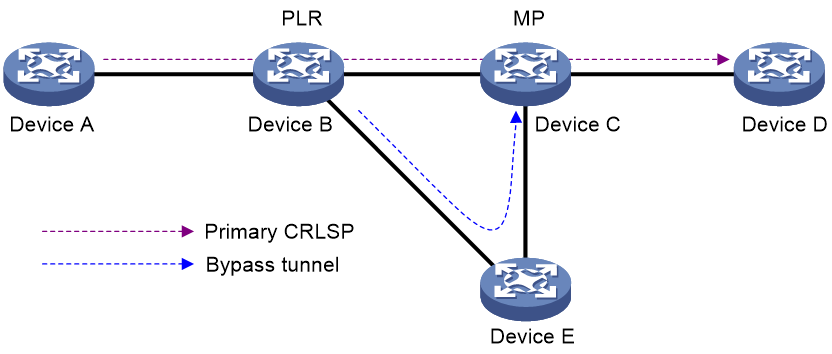
· Link protection—This mode is also called next-hop (NHOP) protection. The Point of Local Repair (PLR) and the Merge Point (MP) are connected through a direct link and the primary CRLSP traverses this link. When the link fails, traffic is switched to the bypass tunnel. As shown in Figure 1, the primary CRLSP is Device A—Device B—Device C—Device D, and the bypass tunnel is Device B—Device E—Device C.
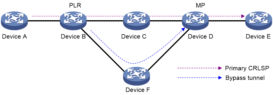
· Node protection—This mode is also called next-next-hop (NNHOP) protection. The PLR and the MP are connected through a device and the primary CRLSP traverses this device. When the device fails, traffic is switched to the bypass tunnel. As shown in Figure 2, the primary CRLSP is Device A—Device B—Device C—Device D—Device E, and the bypass tunnel is Device B—Device F—Device D. Device C is the protected device.
This configuration example describes how to configure MPLS TE FRR that provides link protection.
Prerequisites
The following information applies to Comware 9-based routers. Procedures and information in the examples might be slightly different depending on the software or hardware version of the routers.
The configuration examples were created and verified in a lab environment, and all the devices were started with the factory default configuration. When you are working on a live network, make sure you understand the potential impact of every command on your network.
The following information is provided based on the assumption that you have basic knowledge of MPLS TE.
Example: Establishing an MPLS TE tunnel with RSVP-TE
Network configuration
As shown in Figure 3, Enterprise A and Enterprise B each have a headquarters and a branch, which are interconnected through the carrier's MPLS network. The branches have important data to back up to the servers of their respective headquarters. The maximum bandwidth for the data traffic of Enterprise A is 20000 kbps, while the maximum bandwidth for the data traffic of Enterprise B is 30000 kbps.
On the MPLS network, the maximum bandwidth and maximum reservable bandwidth of each link is 50000 kbps and 40000 kbps. Deploy RSVP-TE on the MPLS network to automatically establish MPLS TE tunnels that meet the bandwidth requirements of the enterprises.
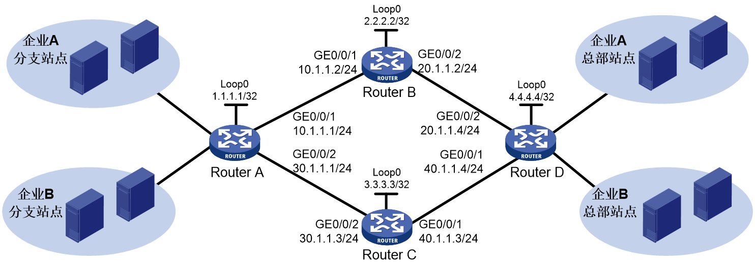
Analysis
· To use RSVP-TE to configure MPLS TE tunnels, configure MPLS, MPLS TE, and RSVP-TE on the backbone network.
· To allow the two enterprise users to simultaneously transmit data over the MPLS network of the carrier with guaranteed tunnel bandwidth, configure a tunnel interface and specify the tunnel bandwidth for each user on the ingress node.
· To ensure the that each link has enough bandwidth, configure MPLS TE attributes for links on each interface that the MPLS TE tunnels traverse to specify the link maximum bandwidth and maximum reservable bandwidth.
· To generate TE database (TEDB) on each node to calculate the constraints-compliant shortest paths to specific nodes, configure OSPF to support MPLS TE on the backbone so that network nodes can advertise MPLS TE attributes of links through OSPF routes.
· To use RSVP-TE to allocate MPLS TE labels to establish CRLSPs, configure the MPLS TE tunnel ingress nodes to automatically establish CRLSPs through RSVP-TE.
· To forward traffic along MPLS TE tunnels, configure static routes on the tunnel ingress nodes to direct traffic to the MPLS TE tunnels.
Software versions used
This configuration example was created and verified on R9141P16 of the MSR2630E-X1 device.
Restrictions and guidelines
To use RSVP-TE for dynamic CRLSP establishment, you must configure the TE extension for the IGP to generate TEDB.
The device supports OSPF TE and IS-IS TE. Without TE extension support, paths are calculated based on IGP routes rather than by the Constraint-based Shortest Path First (CSPF) algorithm.
Procedures
Table 1 Assigning IP addresses to the network interfaces
Configure IP addresses and masks for interfaces as shown in Figure 3. (Details not shown.)
Table 2 Configure OSPF on each router to ensure IP connectivity between them:
# Configure Router A.
<RouterA> System-view
[RouterA] ospf
[RouterA-ospf-1] area 0
[RouterA-ospf-1-area-0.0.0.0] network 1.1.1.1 0.0.0.0
[RouterA-ospf-1-area-0.0.0.0] network 10.1.1.0 0.0.0.255
[RouterA-ospf-1-area-0.0.0.0] network 30.1.1.0 0.0.0.255
[RouterA-ospf-1-area-0.0.0.0] quit
[RouterA-ospf-1] quit
# Configure Router B.
<RouterB> System-view
[RouterB] ospf
[RouterB-ospf-1] area 0
[RouterB-ospf-1-area-0.0.0.0] network 2.2.2.2 0.0.0.0
[RouterB-ospf-1-area-0.0.0.0] network 10.1.1.0 0.0.0.255
[RouterB-ospf-1-area-0.0.0.0] network 20.1.1.0 0.0.0.255
[RouterB-ospf-1-area-0.0.0.0] quit
[RouterB-ospf-1] quit
# Configure Router C.
<RouterC> System-view
[RouterC] ospf
[RouterC-ospf-1] area 0
[RouterC-ospf-1-area-0.0.0.0] network 3.3.3.3 0.0.0.0
[RouterC-ospf-1-area-0.0.0.0] network 30.1.1.0 0.0.0.255
[RouterC-ospf-1-area-0.0.0.0] network 40.1.1.0 0.0.0.255
[RouterC-ospf-1-area-0.0.0.0] quit
[RouterC-ospf-1] quit
Configure Router D.
<RouterD> System-view
[RouterD] ospf
[RouterD-ospf-1] area 0
[RouterD-ospf-1-area-0.0.0.0] network 4.4.4.4 0.0.0.0
[RouterD-ospf-1-area-0.0.0.0] network 20.1.1.0 0.0.0.255
[RouterD-ospf-1-area-0.0.0.0] network 40.1.1.0 0.0.0.255
[RouterD-ospf-1-area-0.0.0.0] quit
[RouterD-ospf-1] quit
# After the configuration is completed, execute the display ip routing-table command on each router to verify that the routers have learned the routes to each other, including the loopback interface routes. Take Router A as an example:
[RouterA] display ip routing-table
Destinations : 21 Routes : 21
Destination/Mask Proto Pre Cost NextHop Interface
0.0.0.0/32 Direct 0 0 127.0.0.1 InLoop0
1.1.1.1/32 Direct 0 0 127.0.0.1 InLoop0
2.2.2.2/32 O_INTRA 10 1 10.1.1.2 GE0/0/1
3.3.3.3/32 O_INTRA 10 1 30.1.1.3 GE0/0/2
4.4.4.4/32 O_INTRA 10 2 10.1.1.2 GE0/0/1
10.1.1.0/24 Direct 0 0 10.1.1.1 GE0/0/1
10.1.1.0/32 Direct 0 0 10.1.1.1 GE0/0/1
10.1.1.1/32 Direct 0 0 127.0.0.1 InLoop0
10.1.1.255/32 Direct 0 0 10.1.1.1 GE0/0/1
20.1.1.0/24 O_INTRA 10 2 10.1.1.2 GE0/0/1
30.1.1.0/24 Direct 0 0 30.1.1.1 GE0/0/2
30.1.1.0/32 Direct 0 0 30.1.1.1 GE0/0/2
30.1.1.1/32 Direct 0 0 127.0.0.1 InLoop0
30.1.1.255/32 Direct 0 0 30.1.1.1 GE0/0/2
127.0.0.0/8 Direct 0 0 127.0.0.1 InLoop0
127.0.0.0/32 Direct 0 0 127.0.0.1 InLoop0
127.0.0.1/32 Direct 0 0 127.0.0.1 InLoop0
127.255.255.255/32 Direct 0 0 127.0.0.1 InLoop0
224.0.0.0/4 Direct 0 0 0.0.0.0 NULL0
224.0.0.0/24 Direct 0 0 0.0.0.0 NULL0
255.255.255.255/32 Direct 0 0 127.0.0.1 InLoop0
Table 3 Configure the LSR ID, enable MPLS, MPLS TE, and RSVP-TE on each router:
# Configure Router A.
[RouterA] mpls lsr-id 1.1.1.1
[RouterA] mpls te
[RouterA-te] quit
[RouterA] rsvp
[RouterA-rsvp] quit
[RouterA] interface gigabitethernet 0/0/1
[RouterA-GigabitEthernet0/0/1] mpls enable
[RouterA-GigabitEthernet0/0/1] mpls te enable
[RouterA-GigabitEthernet0/0/1] rsvp enable
[RouterA-GigabitEthernet0/0/1] quit
[RouterA] interface gigabitethernet 0/0/2
[RouterA-GigabitEthernet0/0/2] mpls enable
[RouterA-GigabitEthernet0/0/2] mpls te enable
[RouterA-GigabitEthernet0/0/2] rsvp enable
[RouterA-GigabitEthernet0/0/2] quit
# Configure Router B.
[RouterB] mpls lsr-id 2.2.2.2
[RouterB] mpls te
[RouterB-te] quit
[RouterB] rsvp
[RouterB-rsvp] quit
[RouterB] interface gigabitethernet 0/0/1
[RouterB-GigabitEthernet0/0/1] mpls enable
[RouterB-GigabitEthernet0/0/1] mpls te enable
[RouterB-GigabitEthernet0/0/1] rsvp enable
[RouterB-GigabitEthernet0/0/1] quit
[RouterB] interface gigabitethernet 0/0/2
[RouterB-GigabitEthernet0/0/2] mpls enable
[RouterB-GigabitEthernet0/0/2] mpls te enable
[RouterB-GigabitEthernet0/0/2] rsvp enable
[RouterB-GigabitEthernet0/0/2] quit
# Configure Router C.
[RouterC] mpls lsr-id 3.3.3.3
[RouterC] mpls te
[RouterC-te] quit
[RouterC] rsvp
[RouterC-rsvp] quit
[RouterC] interface gigabitethernet 0/0/1
[RouterC-GigabitEthernet0/0/1] mpls enable
[RouterC-GigabitEthernet0/0/1] mpls te enable
[RouterC-GigabitEthernet0/0/1] rsvp enable
[RouterC-GigabitEthernet0/0/1] quit
[RouterC] interface gigabitethernet 0/0/2
[RouterC-GigabitEthernet0/0/2] mpls enable
[RouterC-GigabitEthernet0/0/2] mpls te enable
[RouterC-GigabitEthernet0/0/2] rsvp enable
[RouterC-GigabitEthernet0/0/2] quit
Configure Router D.
[RouterD] mpls lsr-id 4.4.4.4
[RouterD] mpls te
[RouterD-te] quit
[RouterD] rsvp
[RouterD-rsvp] quit
[RouterD] interface gigabitethernet 0/0/1
[RouterD-GigabitEthernet0/0/1] mpls enable
[RouterD-GigabitEthernet0/0/1] mpls te enable
[RouterD-GigabitEthernet0/0/1] rsvp enable
[RouterD-GigabitEthernet0/0/1] quit
[RouterD] interface gigabitethernet 0/0/2
[RouterD-GigabitEthernet0/0/2] mpls enable
[RouterD-GigabitEthernet0/0/2] mpls te enable
[RouterD-GigabitEthernet0/0/2] rsvp enable
[RouterD-GigabitEthernet0/0/2] quit
Table 4 Configure MPLS TE attributes for links:
# Configure the maximum link bandwidth and maximum reservable bandwidth on Router A.
[RouterA] interface gigabitethernet 0/0/1
[RouterA-GigabitEthernet0/0/1] mpls te max-link-bandwidth 50000
[RouterA-GigabitEthernet0/0/1] mpls te max-reservable-bandwidth 40000
[RouterA-GigabitEthernet0/0/1] quit
[RouterA] interface gigabitethernet 0/0/2
[RouterA-GigabitEthernet0/0/2] mpls te max-link-bandwidth 50000
[RouterA-GigabitEthernet0/0/2] mpls te max-reservable-bandwidth 40000
[RouterA-GigabitEthernet0/0/2] quit
# Configure the maximum link bandwidth and maximum reservable bandwidth on Router B.
[RouterB] interface gigabitethernet 0/0/1
[RouterB-GigabitEthernet0/0/1] mpls te max-link-bandwidth 50000
[RouterB-GigabitEthernet0/0/1] mpls te max-reservable-bandwidth 40000
[RouterB-GigabitEthernet0/0/1] quit
[RouterB] interface gigabitethernet 0/0/2
[RouterB-GigabitEthernet0/0/2] mpls te max-link-bandwidth 50000
[RouterB-GigabitEthernet0/0/2] mpls te max-reservable-bandwidth 40000
[RouterB-GigabitEthernet0/0/2] quit
# Configure the maximum link bandwidth and maximum reservable bandwidth on Router C.
[RouterC] interface gigabitethernet 0/0/1
[RouterC-GigabitEthernet0/0/1] mpls te max-link-bandwidth 50000
[RouterC-GigabitEthernet0/0/1] mpls te max-reservable-bandwidth 40000
[RouterC-GigabitEthernet0/0/1] quit
[RouterC] interface gigabitethernet 0/0/2
[RouterC-GigabitEthernet0/0/2] mpls te max-link-bandwidth 50000
[RouterC-GigabitEthernet0/0/2] mpls te max-reservable-bandwidth 40000
[RouterC-GigabitEthernet0/0/2] quit
# Configure the maximum link bandwidth and maximum reservable bandwidth on Router D.
[RouterD] interface gigabitethernet 0/0/1
[RouterD-GigabitEthernet0/0/1] mpls te max-link-bandwidth 50000
[RouterD-GigabitEthernet0/0/1] mpls te max-reservable-bandwidth 40000
[RouterD-GigabitEthernet0/0/1] quit
[RouterD] interface gigabitethernet 0/0/2
[RouterD-GigabitEthernet0/0/2] mpls te max-link-bandwidth 50000
[RouterD-GigabitEthernet0/0/2] mpls te max-reservable-bandwidth 40000
[RouterD-GigabitEthernet0/0/2] quit
Table 5 Configure OSPF TE to advertise the MPLS TE attributes of links:
# On Router A, enable opaque LSA advertisement and reception (enabled by default), and enable MPLS TE in OSPF area 0.
[RouterA] ospf
[RouterA-ospf-1] opaque-capability enable
[RouterA-ospf-1] area 0
[RouterA-ospf-1-area-0.0.0.0] mpls te enable
[RouterA-ospf-1-area-0.0.0.0] quit
[RouterA-ospf-1] quit
# On Router B, enable opaque LSA advertisement and reception (enabled by default), and enable MPLS TE in OSPF area 0.
[RouterB] ospf
[RouterB-ospf-1] opaque-capability enable
[RouterB-ospf-1] area 0
[RouterB-ospf-1-area-0.0.0.0] mpls te enable
[RouterB-ospf-1-area-0.0.0.0] quit
[RouterB-ospf-1] quit
# On Router C, enable opaque LSA advertisement and reception (enabled by default), and enable MPLS TE in OSPF area 0.
[RouterC] ospf
[RouterC-ospf-1] opaque-capability enable
[RouterC-ospf-1] area 0
[RouterC-ospf-1-area-0.0.0.0] mpls te enable
[RouterC-ospf-1-area-0.0.0.0] quit
[RouterC-ospf-1] quit
# On Router D, enable opaque LSA advertisement and reception (enabled by default), and enable MPLS TE in OSPF area 0.
[RouterD] ospf
[RouterD-ospf-1] opaque-capability enable
[RouterD-ospf-1] area 0
[RouterD-ospf-1-area-0.0.0.0] mpls te enable
[RouterD-ospf-1-area-0.0.0.0] quit
[RouterD-ospf-1] quit
Table 6 Configure MPLS tunnels:
# On Router A, configure MPLS TE tunnel interface Tunnel 1 to transfer data for enterprise A. Specify the tunnel destination address as the LSR ID of Router D (4.4.4.4), use RSVP-TE as the MPLS TE tunnel signaling protocol, assign 20000 kbps bandwidth to the tunnel, and enable route recording.
[RouterA] interface tunnel 1 mode mpls-te
[RouterA-Tunnel1] ip address 7.1.1.1 255.255.255.0
[RouterA-Tunnel1] destination 4.4.4.4
[RouterA-Tunnel1] mpls te signaling rsvp-te
[RouterA-Tunnel1] mpls te bandwidth 20000
[RouterA-Tunnel1] mpls te record-route
[RouterA-Tunnel1] quit
# On Router A, configure MPLS TE tunnel interface Tunnel 2 to transfer data for enterprise A. Specify the tunnel destination address as the LSR ID of Router D (4.4.4.4), use RSVP-TE as the MPLS TE tunnel signaling protocol, assign 30000 kbps bandwidth to the tunnel, and enable route recording.
[RouterA] interface tunnel 2 mode mpls-te
[RouterA-Tunnel2] ip address 8.1.1.1 255.255.255.0
[RouterA-Tunnel2] destination 4.4.4.4
[RouterA-Tunnel2] mpls te signaling rsvp-te
[RouterA-Tunnel2] mpls te bandwidth 30000
[RouterA-Tunnel2] mpls te record-route
[RouterA-Tunnel2] quit
Table 7 Configure static routes on Router A to direct traffic to MPLS TE tunnels.
# Configure a static route to direct the traffic destined for subnet 20.1.1.0/24 to MPLS TE tunnel 1.
[RouterA] ip route-static 20.1.1.0 24 tunnel 1 preference 1
# Configure a static route to direct the traffic destined for subnet 40.1.1.0/24 to MPLS TE tunnel 2.
[RouterA] ip route-static 40.1.1.0 24 tunnel 2 preference 1
Verifying the configuration
# After the configuration is completed, execute the display interface tunnel command on Router A to verify that the two tunnel interfaces are up.
[RouterA] display interface tunnel
Tunnel1
Current state: Up
Line protocol state: Up
Description: Tunnel1 Interface
Bandwidth: 64kbps
Maximum Transmit Unit: 64000
Internet Address is 7.1.1.1/24 Primary
Tunnel source unknown, destination 4.4.4.4
Tunnel TTL 255
Tunnel protocol/transport CR_LSP
Output queue - Urgent queuing: Size/Length/Discards 0/100/0
Output queue - Protocol queuing: Size/Length/Discards 0/500/0
Output queue - FIFO queuing: Size/Length/Discards 0/75/0
Last clearing of counters: Never
Last 300 seconds input rate: 0 bytes/sec, 0 bits/sec, 0 packets/sec
Last 300 seconds output rate: 0 bytes/sec, 0 bits/sec, 0 packets/sec
Input: 0 packets, 0 bytes, 0 drops
Output: 0 packets, 0 bytes, 0 drops
Tunnel2
Current state: Up
Line protocol state: Up
Description: Tunnel2 Interface
Bandwidth: 64kbps
Maximum Transmit Unit: 64000
Internet Address is 8.1.1.1/24 Primary
Tunnel source unknown, destination 4.4.4.4
Tunnel TTL 255
Tunnel protocol/transport CR_LSP
Output queue - Urgent queuing: Size/Length/Discards 0/100/0
Output queue - Protocol queuing: Size/Length/Discards 0/500/0
Output queue - FIFO queuing: Size/Length/Discards 0/75/0
Last clearing of counters: Never
Last 300 seconds input rate: 0 bytes/sec, 0 bits/sec, 0 packets/sec
Last 300 seconds output rate: 0 bytes/sec, 0 bits/sec, 0 packets/sec
Input: 0 packets, 0 bytes, 0 drops
Output: 0 packets, 0 bytes, 0 drops
# Execute the display mpls te tunnel-interface command on Router A to view details of the two tunnels.
[RouterA] display mpls te tunnel-interface
Tunnel Name : Tunnel 1
Tunnel State : Up (Main CRLSP up, Shared-resource CRLSP down)
Tunnel Attributes :
LSP ID : 46362 Tunnel ID : 1
Admin State : Normal
Ingress LSR ID : 1.1.1.1 Egress LSR ID : 4.4.4.4
Signaling : RSVP-TE Static CRLSP Name : -
Resv Style : SE
Tunnel mode : -
Reverse-LSP name : -
Reverse-LSP LSR ID : - Reverse-LSP Tunnel ID: -
Class Type : CT0 Tunnel Bandwidth : 20000 kbps
Reserved Bandwidth : 20000 kbps
Setup Priority : 7 Holding Priority : 7
Affinity Attr/Mask : 0/0
Explicit Path : -
Backup Explicit Path : -
Metric Type : TE
Record Route : Enabled Record Label : Disabled
FRR Flag : Disabled Bandwidth Protection : Disabled
Backup Bandwidth Flag: Disabled Backup Bandwidth Type: -
Backup Bandwidth : -
Bypass Tunnel : No Auto Created : No
Route Pinning : Disabled
Retry Limit : 3 Retry Interval : 2 sec
Reoptimization : Disabled Reoptimization Freq : -
Backup Type : None Backup LSP ID : -
Auto Bandwidth : Disabled Auto Bandwidth Freq : -
Min Bandwidth : - Max Bandwidth : -
Collected Bandwidth : -
Tunnel Name : Tunnel 2
Tunnel State : Up (Main CRLSP up, Shared-resource CRLSP down)
Tunnel Attributes :
LSP ID : 46362 Tunnel ID : 2
Admin State : Normal
Ingress LSR ID : 1.1.1.1 Egress LSR ID : 4.4.4.4
Signaling : RSVP-TE Static CRLSP Name : -
Resv Style : SE
Tunnel mode : -
Reverse-LSP name : -
Reverse-LSP LSR ID : - Reverse-LSP Tunnel ID: -
Class Type : CT0 Tunnel Bandwidth : 30000 kbps
Reserved Bandwidth : 30000 kbps
Setup Priority : 7 Holding Priority : 7
Affinity Attr/Mask : 0/0
Explicit Path : -
Backup Explicit Path : -
Metric Type : TE
Record Route : Enabled Record Label : Disabled
FRR Flag : Disabled Bandwidth Protection : Disabled
Backup Bandwidth Flag: Disabled Backup Bandwidth Type: -
Backup Bandwidth : -
Bypass Tunnel : No Auto Created : No
Route Pinning : Disabled
Retry Limit : 3 Retry Interval : 2 sec
Reoptimization : Disabled Reoptimization Freq : -
Backup Type : None Backup LSP ID : -
Auto Bandwidth : Disabled Auto Bandwidth Freq : -
Min Bandwidth : - Max Bandwidth : -
Collected Bandwidth : -
# Execute the display ip routing-table command on Router A. The output shows that the routing table contains static routes that uses Tunnel1 and Tunnel2 as the outgoing interfaces.
[RouterA] display ip routing-table
Destinations : 30 Routes : 30
Destination/Mask Proto Pre Cost NextHop Interface
0.0.0.0/32 Direct 0 0 127.0.0.1 InLoop0
1.1.1.1/32 Direct 0 0 127.0.0.1 InLoop0
2.2.2.2/32 O_INTRA 10 1 10.1.1.2 GE0/0/1
3.3.3.3/32 O_INTRA 10 1 30.1.1.3 GE0/0/2
4.4.4.4/32 O_INTRA 10 2 10.1.1.2 GE0/0/1
7.1.1.0/24 Direct 0 0 7.1.1.1 Tun1
7.1.1.0/32 Direct 0 0 7.1.1.1 Tun1
7.1.1.1/32 Direct 0 0 127.0.0.1 InLoop0
7.1.1.255/32 Direct 0 0 7.1.1.1 Tun1
8.1.1.0/24 Direct 0 0 8.1.1.1 Tun2
8.1.1.0/32 Direct 0 0 8.1.1.1 Tun2
8.1.1.1/32 Direct 0 0 127.0.0.1 InLoop0
8.1.1.255/32 Direct 0 0 8.1.1.1 Tun2
10.1.1.0/24 Direct 0 0 10.1.1.1 GE0/0/1
10.1.1.0/32 Direct 0 0 10.1.1.1 GE0/0/1
10.1.1.1/32 Direct 0 0 127.0.0.1 InLoop0
10.1.1.255/32 Direct 0 0 10.1.1.1 GE0/0/1
20.1.1.0/24 Static 1 0 0.0.0.0 Tun1
30.1.1.0/24 Direct 0 0 30.1.1.1 GE0/0/2
30.1.1.0/32 Direct 0 0 30.1.1.1 GE0/0/2
30.1.1.1/32 Direct 0 0 127.0.0.1 InLoop0
30.1.1.255/32 Direct 0 0 30.1.1.1 GE0/0/2
40.1.1.0/24 Static 1 0 0.0.0.0 Tun2
127.0.0.0/8 Direct 0 0 127.0.0.1 InLoop0
127.0.0.0/32 Direct 0 0 127.0.0.1 InLoop0
127.0.0.1/32 Direct 0 0 127.0.0.1 InLoop0
127.255.255.255/32 Direct 0 0 127.0.0.1 InLoop0
224.0.0.0/4 Direct 0 0 0.0.0.0 NULL0
224.0.0.0/24 Direct 0 0 0.0.0.0 NULL0
255.255.255.255/32 Direct 0 0 127.0.0.1 InLoop0
# Execute the display rsvp lsp verbose command on Router A. The output shows that the CRLSP of Tunnel 1 uses path Router A—Router B—Router D and that of Tunnel 2 uses path Router A—Router C—Router D.
[RouterA] display rsvp lsp verbose
Tunnel name: RouterA_t1
Destination: 4.4.4.4 Source: 1.1.1.1
Tunnel ID: 1 LSP ID: 46362
LSR type: Ingress Direction: Unidirectional
Setup priority: 7 Holding priority: 7
In-Label: - Out-Label: 1150
In-Interface: - Out-Interface: GE0/0/1
Nexthop: 10.1.1.2 Exclude-any: 0
Include-Any: 0 Include-all: 0
Mean rate (CIR): 20000 kbps Mean burst size (CBS): 1000.00 bytes
Path MTU: 1500 Class type: CT0
RRO number: 6
10.1.1.1/32 Flag: 0x00 (No FRR)
10.1.1.2/32 Flag: 0x40 (No FRR/In-Int)
2.2.2.2/32 Flag: 0x20 (No FRR/Node-ID)
20.1.1.2/32 Flag: 0x00 (No FRR)
20.1.1.4/32 Flag: 0x40 (No FRR/In-Int)
4.4.4.4/32 Flag: 0x20 (No FRR/Node-ID)
Fast Reroute protection: None
Tunnel name: RouterA_t2
Destination: 4.4.4.4 Source: 1.1.1.1
Tunnel ID: 2 LSP ID: 46362
LSR type: Ingress Direction: Unidirectional
Setup priority: 7 Holding priority: 7
In-Label: - Out-Label: 1150
In-Interface: - Out-Interface: GE0/0/2
Nexthop: 30.1.1.3 Exclude-any: 0
Include-Any: 0 Include-all: 0
Mean rate (CIR): 30000 kbps Mean burst size (CBS): 1000.00 bytes
Path MTU: 1500 Class type: CT0
RRO number: 6
30.1.1.1/32 Flag: 0x00 (No FRR)
30.1.1.3/32 Flag: 0x40 (No FRR/In-Int)
3.3.3.3/32 Flag: 0x20 (No FRR/Node-ID)
40.1.1.3/32 Flag: 0x00 (No FRR)
40.1.1.4/32 Flag: 0x40 (No FRR/In-Int)
4.4.4.4/32 Flag: 0x20 (No FRR/Node-ID)
Fast Reroute protection: None
The previous verification shows that RSVP-TE has automatically established two CRLSPs for the two enterprise users. One CRLSP passes Router A—Router B—Router D and has 20000 kbps bandwidth. The other CRLSP passes Router A—Router C—Router D and has 30000 kbps bandwidth.
Configuration files
· Router A:
#
ospf 1
area 0.0.0.0
network 1.1.1.1 0.0.0.0
network 10.1.1.0 0.0.0.255
network 30.1.1.0 0.0.0.255
mpls te enable
#
mpls lsr-id 1.1.1.1
#
mpls te
#
rsvp
#
interface LoopBack0
ip address 1.1.1.1 255,255,255,255
#
interface GigabitEthernet0/0/1
port link-mode route
ip address 10.1.1.1 255.255.255.0
mpls enable
mpls te enable
mpls te max-link-bandwidth 50000
mpls te max-reservable-bandwidth 40000
rsvp enable
#
interface GigabitEthernet0/0/2
port link-mode route
ip address 30.1.1.1 255.255.255.0
mpls enable
mpls te enable
mpls te max-link-bandwidth 50000
mpls te max-reservable-bandwidth 40000
rsvp enable
#
interface Tunnel1 mode mpls-te
ip address 7.1.1.1 255.255.255.0
mpls te bandwidth ct0 20000
mpls te record-route
destination 4.4.4.4
#
interface Tunnel2 mode mpls-te
ip address 8.1.1.1 255.255.255.0
mpls te bandwidth ct0 30000
mpls te record-route
destination 4.4.4.4
#
ip route-static 20.1.1.0 24 Tunnel1 preference 1
ip route-static 40.1.1.0 24 Tunnel2 preference 1
#
· Router B:
#
ospf 1
area 0.0.0.0
network 2.2.2.2 0.0.0.0
network 10.1.1.0 0.0.0.255
network 20.1.1.0 0.0.0.255
mpls te enable
#
mpls lsr-id 2.2.2.2
#
mpls te
#
rsvp
#
interface LoopBack0
ip address 2.2.2.2 255,255,255,255
#
interface GigabitEthernet0/0/1
port link-mode route
ip address 10.1.1.2 255.255.255.0
mpls enable
mpls te enable
mpls te max-link-bandwidth 50000
mpls te max-reservable-bandwidth 40000
rsvp enable
#
interface GigabitEthernet0/0/2
port link-mode route
ip address 20.1.1.2 255.255.255.0
mpls enable
mpls te enable
mpls te max-link-bandwidth 50000
mpls te max-reservable-bandwidth 40000
rsvp enable
#
· Router C:
#
ospf 1
area 0.0.0.0
network 3.3.3.3 0.0.0.0
network 30.1.1.0 0.0.0.255
network 40.1.1.0 0.0.0.255
mpls te enable
#
mpls lsr-id 3.3.3.3
#
mpls te
#
rsvp
#
interface LoopBack0
ip address 3.3.3.3 255.255.255.0
#
interface GigabitEthernet0/0/1
port link-mode route
ip address 40.1.1.3 255.255.255.0
mpls enable
mpls te enable
mpls te max-link-bandwidth 50000
mpls te max-reservable-bandwidth 40000
rsvp enable
#
interface GigabitEthernet0/0/2
port link-mode route
ip address 30.1.1.3 255.255.255.0
mpls enable
mpls te enable
mpls te max-link-bandwidth 50000
mpls te max-reservable-bandwidth 40000
rsvp enable
#
· Router D:
#
ospf 1
area 0.0.0.0
network 4.4.4.4 0.0.0.0
network 20.1.1.0 0.0.0.255
network 40.1.1.0 0.0.0.255
mpls te enable
#
mpls lsr-id 4.4.4.4
#
mpls te
#
rsvp
#
interface LoopBack0
ip address 4.4.4.4 255,255,255,255
#
interface GigabitEthernet0/0/1
port link-mode route
ip address 40.1.1.4 255.255.255.0
mpls enable
mpls te enable
mpls te max-link-bandwidth 50000
mpls te max-reservable-bandwidth 40000
rsvp enable
#
interface GigabitEthernet0/0/2
port link-mode route
ip address 20.1.1.4 255.255.255.0
mpls enable
mpls te enable
mpls te max-link-bandwidth 50000
mpls te max-reservable-bandwidth 40000
rsvp enable
#
Example: Configuring MPLS TE FRR
Network configuration
As shown in Figure 4, establish a CRLSP over Router A->Router B->Router C->Router D to carry the voice service of an enterprise. Router B and Router C are located far apart, with multiple Layer 2 switches and an unstable link in between. Link failure will probably occur. Therefore, use MPLS TE FRR to protect the link between Router B and Router C. In case of a link failure, it should be able to quickly switch traffic to the bypass CRLSP (Router A -> Router B -> Router E -> Router C -> Router D). (Assume the required bandwidth for both the primary and bypass tunnels is 30000 kbps, with a maximum bandwidth of 50000 kbps for each link and maximum available reserved bandwidth of 40000 kbps.)
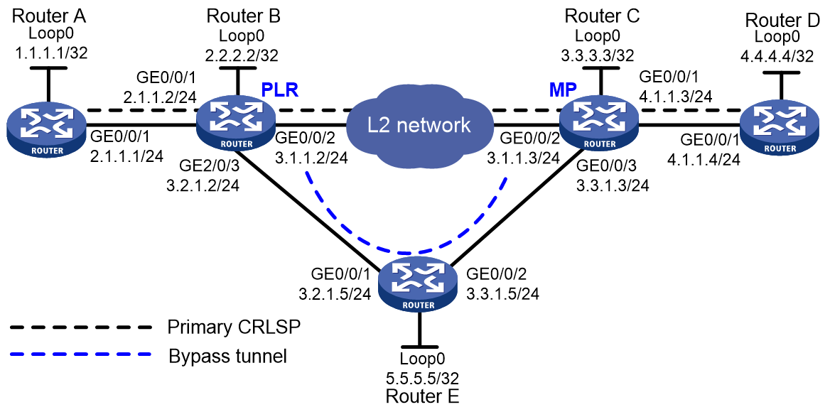
Analysis
· To establish primary and bypass CRLSPs, enable MPLS, MPLS TE, and RSVP-TE on each router.
· As the paths for the primary CRLSP and bypass CRLSP have been explicitly specified in the networking requirements, you must configure the MPLS TE tunnel to use the explicit paths of the primary CRLSP and bypass CRLSP.
· To enable the PLR to quickly detect the failure of the protected primary CRLSP link, configure BFD for RSVP-TE on the two ends of the protected link (Router B and Router C), so that BFD can quickly detect link failure and notify RSVP-TE to switch traffic to the bypass tunnel.
· To ensure quick traffic switchover to the bypass CRLSP in case of a link failure detected by BFD, configure MPLS TE FRR on the ingress node of the primary CRLSP.
· To ensure that MPLS TE can select the optimal bypass tunnel for link failure when multiple bypass tunnels are available, set the optimal bypass tunnel selection interval to 5 seconds (300 seconds by default) on the PLR node of FRR.
Software versions used
This configuration example was created and verified on R9141P16 of the MSR2630E-X1 device.
Restrictions and guidelines
· Only MPLS TE tunnels established through RSVP-TE support FRR.
· Do not configure both FRR and RSVP authentication on the same interface.
· Bypass tunnels are pre-established and require extra bandwidth. Use bypass tunnels to protect only critical interfaces or links when bandwidth is insufficient.
· Make sure the bandwidth assigned to the bypass tunnel is no less than the total bandwidth needed by all primary CRLSPs to be protected by the bypass tunnel. Otherwise, some primary CRLSPs might not be protected by the bypass tunnel.
· A bypass tunnel typically does not forward data when the primary CRLSP operates correctly. For a bypass tunnel to also forward data during tunnel protection, you must assign adequate bandwidth to the bypass tunnel.
· A bypass tunnel cannot be used for services such as VPN.
· FRR cannot be configured for a bypass tunnel. A bypass tunnel cannot act as a primary CRLSP.
· A bypass tunnel must not traverse the protected node or interface.
· When a primary CRLSP that requires no bandwidth protection is associated with a bypass tunnel that provides bandwidth protection, the primary CRLSP can occupy the bandwidth of the bypass tunnel. If the bypass tunnel also protects other primary CRLSPs, the primary CRLSP that comes up first occupies the bandwidth of the bypass tunnel. A primary CRLSP that needs bandwidth protection cannot preempt the one that does not need bandwidth protection.
· After an FRR, the primary CRLSP will be down if you modify the bandwidth that the bypass tunnel can protect and your modification results in one of the following:
¡ The CT type changes.
¡ The bypass tunnel cannot protect adequate bandwidth as configured.
¡ FRR protection type changes (whether or not to provide bandwidth protection for the primary CRLSP).
Procedures
Table 1 Assign IP addresses to the network interfaces
Configure IP addresses and masks for interfaces as shown in Figure 4. (Details not shown.)
Table 2 Configure OSPF on each router to ensure IP connectivity between them:
# Configure Router A.
<RouterA> System-view
[RouterA] ospf
[RouterA-ospf-1] area 0
[RouterA-ospf-1-area-0.0.0.0] network 1.1.1.1 0.0.0.0
[RouterA-ospf-1-area-0.0.0.0] network 2.1.1.0 0.0.0.255
[RouterA-ospf-1-area-0.0.0.0] quit
[RouterA-ospf-1] quit
# Configure Router B.
<RouterB> System-view
[RouterB] ospf
[RouterB-ospf-1] area 0
[RouterB-ospf-1-area-0.0.0.0] network 2.2.2.2 0.0.0.0
[RouterB-ospf-1-area-0.0.0.0] network 2.1.1.0 0.0.0.255
[RouterB-ospf-1-area-0.0.0.0] network 3.1.1.0 0.0.0.255
[RouterB-ospf-1-area-0.0.0.0] network 3.2.1.0 0.0.0.255
[RouterB-ospf-1-area-0.0.0.0] quit
[RouterB-ospf-1] quit
# Configure Router C.
<RouterC> System-view
[RouterC] ospf
[RouterC-ospf-1] area 0
[RouterC-ospf-1-area-0.0.0.0] network 3.3.3.3 0.0.0.0
[RouterC-ospf-1-area-0.0.0.0] network 3.1.1.0 0.0.0.255
[RouterC-ospf-1-area-0.0.0.0] network 3.3.1.0 0.0.0.255
[RouterC-ospf-1-area-0.0.0.0] network 4.1.1.0 0.0.0.255
[RouterC-ospf-1-area-0.0.0.0] quit
[RouterC-ospf-1] quit
Configure Router D.
<RouterD> System-view
[RouterD] ospf
[RouterD-ospf-1] area 0
[RouterD-ospf-1-area-0.0.0.0] network 4.4.4.4 0.0.0.0
[RouterD-ospf-1-area-0.0.0.0] network 4.1.1.0 0.0.0.255
[RouterD-ospf-1-area-0.0.0.0] quit
[RouterD-ospf-1] quit
Configure Router E.
<RouterE> System-view
[RouterE] ospf
[RouterE-ospf-1] area 0
[RouterE-ospf-1-area-0.0.0.0] network 5.5.5.5 0.0.0.0
[RouterE-ospf-1-area-0.0.0.0] network 3.2.1.0 0.0.0.255
[RouterE-ospf-1-area-0.0.0.0] network 3.3.1.0 0.0.0.255
[RouterE-ospf-1-area-0.0.0.0] quit
[RouterE-ospf-1] quit
# After the configuration is completed, execute the display ip routing-table command on each router to verify that the routers have learned the routes to each other, including the loopback interface routes. Take Router A as an example:
[RouterA] display ip routing-table
Destinations : 19 Routes : 19
Destination/Mask Proto Pre Cost NextHop Interface
0.0.0.0/32 Direct 0 0 127.0.0.1 InLoop0
1.1.1.1/32 Direct 0 0 127.0.0.1 InLoop0
2.1.1.0/24 Direct 0 0 2.1.1.1 GE0/0/1
2.1.1.0/32 Direct 0 0 2.1.1.1 GE0/0/1
2.1.1.1/32 Direct 0 0 127.0.0.1 InLoop0
2.1.1.255/32 Direct 0 0 2.1.1.1 GE0/0/1
2.2.2.2/32 O_INTRA 10 1 2.1.1.2 GE0/0/1
3.1.1.0/24 O_INTRA 10 2 2.1.1.2 GE0/0/1
3.2.1.0/24 O_INTRA 10 2 2.1.1.2 GE0/0/1
3.3.1.0/24 O_INTRA 10 3 2.1.1.2 GE0/0/1
3.3.3.3/32 O_INTRA 10 2 2.1.1.2 GE0/0/1
5.5.5.5/32 O_INTRA 10 2 2.1.1.2 GE0/0/1
127.0.0.0/8 Direct 0 0 127.0.0.1 InLoop0
127.0.0.0/32 Direct 0 0 127.0.0.1 InLoop0
127.0.0.1/32 Direct 0 0 127.0.0.1 InLoop0
127.255.255.255/32 Direct 0 0 127.0.0.1 InLoop0
224.0.0.0/4 Direct 0 0 0.0.0.0 NULL0
224.0.0.0/24 Direct 0 0 0.0.0.0 NULL0
255.255.255.255/32 Direct 0 0 127.0.0.1 InLoop0
Table 3 Configure an LSR ID, and enable MPLS, MPLS TE, and RSVP-TE on each router. Enable BFD for RSVP-TE on Router B and Router C:
# Configure Router A.
[RouterA] mpls lsr-id 1.1.1.1
[RouterA] mpls te
[RouterA-te] quit
[RouterA] rsvp
[RouterA-rsvp] quit
[RouterA] interface gigabitethernet 0/0/1
[RouterA-GigabitEthernet0/0/1] mpls enable
[RouterA-GigabitEthernet0/0/1] mpls te enable
[RouterA-GigabitEthernet0/0/1] rsvp enable
[RouterA-GigabitEthernet0/0/1] quit
# Configure Router B.
[RouterB] mpls lsr-id 2.2.2.2
[RouterB] mpls te
[RouterB-te] quit
[RouterB] rsvp
[RouterB-rsvp] quit
[RouterB] interface gigabitethernet 0/0/1
[RouterB-GigabitEthernet0/0/1] mpls enable
[RouterB-GigabitEthernet0/0/1] mpls te enable
[RouterB-GigabitEthernet0/0/1] rsvp enable
[RouterB-GigabitEthernet0/0/1] quit
[RouterB] interface gigabitethernet 0/0/2
[RouterB-GigabitEthernet0/0/2] mpls enable
[RouterB-GigabitEthernet0/0/2] mpls te enable
[RouterB-GigabitEthernet0/0/2] rsvp enable
[RouterB-GigabitEthernet0/0/2] rsvp bfd enable
[RouterB-GigabitEthernet0/0/2] quit
[RouterB] interface gigabitethernet 0/0/3
[RouterB-GigabitEthernet0/0/3] mpls enable
[RouterB-GigabitEthernet0/0/3] mpls te enable
[RouterB-GigabitEthernet0/0/3] rsvp enable
[RouterB-GigabitEthernet0/0/3] quit
# Configure Router C.
[RouterC] mpls lsr-id 3.3.3.3
[RouterC] mpls te
[RouterC-te] quit
[RouterC] rsvp
[RouterC-rsvp] quit
[RouterC] interface gigabitethernet 0/0/1
[RouterC-GigabitEthernet0/0/1] mpls enable
[RouterC-GigabitEthernet0/0/1] mpls te enable
[RouterC-GigabitEthernet0/0/1] rsvp enable
[RouterC-GigabitEthernet0/0/1] quit
[RouterC] interface gigabitethernet 0/0/2
[RouterC-GigabitEthernet0/0/2] mpls enable
[RouterC-GigabitEthernet0/0/2] mpls te enable
[RouterC-GigabitEthernet0/0/2] rsvp enable
[RouterC-GigabitEthernet0/0/2] rsvp bfd enable
[RouterC-GigabitEthernet0/0/2] quit
[RouterC] interface gigabitethernet 0/0/3
[RouterC-GigabitEthernet0/0/3] mpls enable
[RouterC-GigabitEthernet0/0/3] mpls te enable
[RouterC-GigabitEthernet0/0/3] rsvp enable
[RouterC-GigabitEthernet0/0/3] quit
Configure Router D.
[RouterD] mpls lsr-id 4.4.4.4
[RouterD] mpls te
[RouterD-te] quit
[RouterD] rsvp
[RouterD-rsvp] quit
[RouterD] interface gigabitethernet 0/0/1
[RouterD-GigabitEthernet0/0/1] mpls enable
[RouterD-GigabitEthernet0/0/1] mpls te enable
[RouterD-GigabitEthernet0/0/1] rsvp enable
[RouterD-GigabitEthernet0/0/1] quit
Configure Router E.
[RouterE] mpls lsr-id 5.5.5.5
[RouterE] mpls te
[RouterE-te] quit
[RouterE] rsvp
[RouterE-rsvp] quit
[RouterE] interface gigabitethernet 0/0/1
[RouterE-GigabitEthernet0/0/1] mpls enable
[RouterE-GigabitEthernet0/0/1] mpls te enable
[RouterE-GigabitEthernet0/0/1] rsvp enable
[RouterE-GigabitEthernet0/0/1] quit
[RouterE] interface gigabitethernet 0/0/2
[RouterE-GigabitEthernet0/0/2] mpls enable
[RouterE-GigabitEthernet0/0/2] mpls te enable
[RouterE-GigabitEthernet0/0/2] rsvp enable
[RouterE-GigabitEthernet0/0/2] quit
Table 4 Configure MPLS TE attributes for links:
# Configure the maximum link bandwidth and maximum reservable bandwidth on Router A.
[RouterA] interface gigabitethernet 0/0/1
[RouterA-GigabitEthernet0/0/1] mpls te max-link-bandwidth 50000
[RouterA-GigabitEthernet0/0/1] mpls te max-reservable-bandwidth 40000
[RouterA-GigabitEthernet0/0/1] quit
# Configure the maximum link bandwidth and maximum reservable bandwidth on Router B.
[RouterB] interface gigabitethernet 0/0/1
[RouterB-GigabitEthernet0/0/1] mpls te max-link-bandwidth 50000
[RouterB-GigabitEthernet0/0/1] mpls te max-reservable-bandwidth 40000
[RouterB-GigabitEthernet0/0/1] quit
[RouterB] interface gigabitethernet 0/0/2
[RouterB-GigabitEthernet0/0/2] mpls te max-link-bandwidth 50000
[RouterB-GigabitEthernet0/0/2] mpls te max-reservable-bandwidth 40000
[RouterB-GigabitEthernet0/0/2] quit
[RouterB] interface gigabitethernet 0/0/3
[RouterB-GigabitEthernet0/0/3] mpls te max-link-bandwidth 50000
[RouterB-GigabitEthernet0/0/3] mpls te max-reservable-bandwidth 40000
[RouterB-GigabitEthernet0/0/3] quit
# Configure the maximum link bandwidth and maximum reservable bandwidth on Router C.
[RouterC] interface gigabitethernet 0/0/1
[RouterC-GigabitEthernet0/0/1] mpls te max-link-bandwidth 50000
[RouterC-GigabitEthernet0/0/1] mpls te max-reservable-bandwidth 40000
[RouterC-GigabitEthernet0/0/1] quit
[RouterC] interface gigabitethernet 0/0/2
[RouterC-GigabitEthernet0/0/2] mpls te max-link-bandwidth 50000
[RouterC-GigabitEthernet0/0/2] mpls te max-reservable-bandwidth 40000
[RouterC-GigabitEthernet0/0/2] quit
[RouterC] interface gigabitethernet 0/0/3
[RouterC-GigabitEthernet0/0/3] mpls te max-link-bandwidth 50000
[RouterC-GigabitEthernet0/0/3] mpls te max-reservable-bandwidth 40000
[RouterC-GigabitEthernet0/0/3] quit
# Configure the maximum link bandwidth and maximum reservable bandwidth on Router D.
[RouterD] interface gigabitethernet 0/0/1
[RouterD-GigabitEthernet0/0/1] mpls te max-link-bandwidth 50000
[RouterD-GigabitEthernet0/0/1] mpls te max-reservable-bandwidth 40000
[RouterD-GigabitEthernet0/0/1] quit
# Configure the maximum link bandwidth and maximum reservable bandwidth on Router E.
[RouterE] interface gigabitethernet 0/0/1
[RouterE-GigabitEthernet0/0/1] mpls te max-link-bandwidth 50000
[RouterE-GigabitEthernet0/0/1] mpls te max-reservable-bandwidth 40000
[RouterE-GigabitEthernet0/0/1] quit
[RouterE] interface gigabitethernet 0/0/2
[RouterE-GigabitEthernet0/0/2] mpls te max-link-bandwidth 50000
[RouterE-GigabitEthernet0/0/2] mpls te max-reservable-bandwidth 40000
[RouterE-GigabitEthernet0/0/2] quit
Table 5 Configure OSPF TE to advertise the MPLS TE attributes of links:
# On Router A, enable OSPF opaque LSA advertisement and reception (enabled by default), and enable MPLS TE in OSPF area 0.
[RouterA] ospf
[RouterA-ospf-1] opaque-capability enable
[RouterA-ospf-1] area 0
[RouterA-ospf-1-area-0.0.0.0] mpls te enable
[RouterA-ospf-1-area-0.0.0.0] quit
[RouterA-ospf-1] quit
# On Router B, enable OSPF opaque LSA advertisement and reception (enabled by default), and enable MPLS TE in OSPF area 0.
[RouterB] ospf
[RouterB-ospf-1] opaque-capability enable
[RouterB-ospf-1] area 0
[RouterB-ospf-1-area-0.0.0.0] mpls te enable
[RouterB-ospf-1-area-0.0.0.0] quit
[RouterB-ospf-1] quit
# On Router C, enable OSPF opaque LSA advertisement and reception (enabled by default), and enable MPLS TE in OSPF area 0.
[RouterC] ospf
[RouterC-ospf-1] opaque-capability enable
[RouterC-ospf-1] area 0
[RouterC-ospf-1-area-0.0.0.0] mpls te enable
[RouterC-ospf-1-area-0.0.0.0] quit
[RouterC-ospf-1] quit
# On Router D, enable OSPF opaque LSA advertisement and reception (enabled by default), and enable MPLS TE in OSPF area 0.
[RouterD] ospf
[RouterD-ospf-1] opaque-capability enable
[RouterD-ospf-1] area 0
[RouterD-ospf-1-area-0.0.0.0] mpls te enable
[RouterD-ospf-1-area-0.0.0.0] quit
[RouterD-ospf-1] quit
# On Router E, enable OSPF opaque LSA advertisement and reception (enabled by default), and enable MPLS TE in OSPF area 0.
[RouterE] ospf
[RouterE-ospf-1] opaque-capability enable
[RouterE-ospf-1] area 0
[RouterE-ospf-1-area-0.0.0.0] mpls te enable
[RouterE-ospf-1-area-0.0.0.0] quit
[RouterE-ospf-1] quit
Table 6 Configure an MPLS TE tunnel on Router A, the ingress node of the primary CRLSP:
# Configure an explicit path named pri-path for the primary CRLSP. Use the default strict explicit path mode.
[RouterA] explicit-path pri-path
[RouterA-explicit-path-pri-path] nexthop 2.1.1.2
[RouterA-explicit-path-pri-path] nexthop 3.1.1.3
[RouterA-explicit-path-pri-path] nexthop 4.1.1.4
[RouterA-explicit-path-pri-path] nexthop 4.4.4.4
[RouterA-explicit-path-pri-path] quit
# Configure MPLS TE tunnel interface Tunnel 4 for the primary CRLSP: Specify the tunnel destination address as the LSR ID of Router D (4.4.4.4); use RSVP-TE as the MPLS TE tunnel signaling protocol; assign 30000 kbps bandwidth to the tunnel; and specify the explicit path of tunnel as pri-path.
[RouterA] interface tunnel4 mode mpls-te
[RouterA-Tunnel4] ip address 10.1.1.1 255.255.255.0
[RouterA-Tunnel4] destination 4.4.4.4
[RouterA-Tunnel4] mpls te signaling rsvp-te
[RouterA-Tunnel4] mpls te bandwidth 30000
[RouterA-Tunnel4] mpls te path preference 1 explicit-path pri-path
# Enable FRR for the MPLS TE tunnel.
[RouterA-Tunnel4] mpls te fast-reroute
[RouterA-Tunnel4] quit
# After the configuration is completed, execute the display interface tunnel command on Router A to verify that interface Tunnel4 is up.
[RouterA] display interface tunnel
Tunnel4
Current state: Up
Line protocol state: Up
Description: Tunnel4 Interface
Bandwidth: 64kbps
Maximum Transmit Unit: 64000
Internet Address is 10.1.1.1/24 Primary
Tunnel source unknown, destination 4.4.4.4
Tunnel TTL 255
Tunnel protocol/transport CR_LSP
Output queue - Urgent queuing: Size/Length/Discards 0/100/0
Output queue - Protocol queuing: Size/Length/Discards 0/500/0
Output queue - FIFO queuing: Size/Length/Discards 0/75/0
Last clearing of counters: Never
Last 300 seconds input rate: 0 bytes/sec, 0 bits/sec, 0 packets/sec
Last 300 seconds output rate: 0 bytes/sec, 0 bits/sec, 0 packets/sec
Input: 0 packets, 0 bytes, 0 drops
Output: 0 packets, 0 bytes, 0 drops
# Execute the display mpls te tunnel-interface command on Router A to view details of the tunnel Interface.
[RouterA] display mpls te tunnel-interface
Tunnel Name : Tunnel 4
Tunnel State : Up (Main CRLSP up, Shared-resource CRLSP down)
Tunnel Attributes :
LSP ID : 37325 Tunnel ID : 4
Admin State : Normal
Ingress LSR ID : 1.1.1.1 Egress LSR ID : 4.4.4.4
Signaling : RSVP-TE Static CRLSP Name : -
Resv Style : SE
Tunnel mode : -
Reverse-LSP name : -
Reverse-LSP LSR ID : - Reverse-LSP Tunnel ID: -
Class Type : CT0 Tunnel Bandwidth : 30000 kbps
Reserved Bandwidth : 30000 kbps
Setup Priority : 7 Holding Priority : 7
Affinity Attr/Mask : 0/0
Explicit Path : pri-path
Backup Explicit Path : -
Metric Type : TE
Record Route : Enabled Record Label : Enabled
FRR Flag : Enabled Bandwidth Protection : Disabled
Backup Bandwidth Flag: Disabled Backup Bandwidth Type: -
Backup Bandwidth : -
Bypass Tunnel : No Auto Created : No
Route Pinning : Disabled
Retry Limit : 3 Retry Interval : 2 sec
Reoptimization : Disabled Reoptimization Freq : -
Backup Type : None Backup LSP ID : -
Auto Bandwidth : Disabled Auto Bandwidth Freq : -
Min Bandwidth : - Max Bandwidth : -
Collected Bandwidth : -
Table 7 Configure auto FRR on Router B (the PLR):
# Configure an explicit path named by-path for the bypass tunnel.
[RouterB] explicit-path by-path
[RouterB-explicit-path-by-path] nexthop 3.2.1.5
[RouterB-explicit-path-by-path] nexthop 3.3.1.3
[RouterB-explicit-path-by-path] nexthop 3.3.3.3
[RouterB-explicit-path-by-path] quit
# Configure MPLS TE tunnel interface Tunnel 5 for the bypass tunnel: Specify the tunnel destination address as the LSR ID of Router C (3.3.3.3); use RSVP-TE as the MPLS TE tunnel signaling protocol; assign 30000 kbps bandwidth to the tunnel; and specify the explicit path of tunnel as by-path.
[RouterB] interface tunnel 5 mode mpls-te
[RouterB-Tunnel5] ip address 11.1.1.1 255.255.255.0
[RouterB-Tunnel5] destination 3.3.3.3
[RouterB-Tunnel5] mpls te signaling rsvp-te
[RouterA-Tunnel5] mpls te bandwidth 30000
[RouterB-Tunnel5] mpls te path preference 1 explicit-path by-path
# Configure the bypass tunnel to provide unlimited bandwidth protection.
[RouterB-Tunnel5] mpls te backup bandwidth un-limited
[RouterB-Tunnel5] quit
# Bind the bypass tunnel to the protected interface.
[RouterB] interface gigabitethernet 0/0/2
[RouterB-GigabitEthernet0/0/2] mpls te fast-reroute bypass-tunnel tunnel 5
[RouterB-GigabitEthernet0/0/2] quit
# After the configuration is completed execute the display interface tunnel command on Router B to verify that interface Tunnel5 is up.
[RouterB] display interface tunnel
Tunnel5
Current state: Up
Line protocol state: Down
Description: Tunnel5 Interface
Bandwidth: 64kbps
Maximum Transmit Unit: 64000
Internet Address is 11.1.1.1/24 Primary
Tunnel source unknown, destination 3.3.3.3
Tunnel TTL 255
Tunnel protocol/transport CR_LSP
Output queue - Urgent queuing: Size/Length/Discards 0/100/0
Output queue - Protocol queuing: Size/Length/Discards 0/500/0
Output queue - FIFO queuing: Size/Length/Discards 0/75/0
Last clearing of counters: Never
Last 300 seconds input rate: 0 bytes/sec, 0 bits/sec, 0 packets/sec
Last 300 seconds output rate: 0 bytes/sec, 0 bits/sec, 0 packets/sec
Input: 0 packets, 0 bytes, 0 drops
Output: 0 packets, 0 bytes, 0 drops
Table 8 Configure a static route to direct traffic to the MPLS TE tunnel.
# Configure a static route on Router A to direct the traffic destined for 4.1. 1.0/24 to MPLS TE tunnel 4.
[Router A] ip route-static 4.1.1.0 24 tunnel 4 preference 1
Verifying the configuration
# Execute the display mpls lsp command on each router to view LSP information. The output shows that Router B has two LSPs, and the bypass tunnel backs up the primary CRLSP.
[RouterA] display mpls lsp
FEC Proto In/Out Label Interface/Out NHLFE
1.1.1.1/4/37325 RSVP -/1150 GE0/0/1
2.1.1.2 Local -/- GE0/0/1
Tunnel4 Local -/- NHLFE1026
[RouterB] display mpls lsp
FEC Proto In/Out Label Interface/Out NHLFE
1.1.1.1/4/37325 RSVP 1150/1147 GE0/0/2
Backup 1150/1147 Tun5
2.2.2.2/5/18928 RSVP -/1149 GE0/0/3
3.1.1.3 Local -/- GE0/0/2
3.2.1.5 Local -/- GE0/0/3
Tunnel5 Local -/- NHLFE1027
[RouterC] display mpls lsp
FEC Proto In/Out Label Interface/Out NHLFE
1.1.1.1/4/37325 RSVP 1147/3 GE0/0/1
2.2.2.2/5/18928 RSVP 3/- -
4.1.1.4 Local -/- GE0/0/1
# Shut down the protected interface GigabitEthernet0/0/2 on the PLR (Router B).
[RouterB] interface gigabitethernet 0/0/2
[RouterB-GigabitEthernet0/0/2] shutdown
[RouterB-GigabitEthernet0/0/2] quit
# Execute display interface tunnel 4 command on Router A to verify that interface Tunnel4 is up.
[RouterA] display interface tunnel 4
Tunnel4
Current state: Up
Line protocol state: Up
Description: Tunnel4 Interface
Bandwidth: 64kbps
Maximum Transmit Unit: 64000
Internet Address is 10.1.1.1/24 Primary
Tunnel source unknown, destination 4.4.4.4
Tunnel TTL 255
Tunnel protocol/transport CR_LSP
Output queue - Urgent queuing: Size/Length/Discards 0/100/0
Output queue - Protocol queuing: Size/Length/Discards 0/500/0
Output queue - FIFO queuing: Size/Length/Discards 0/75/0
Last clearing of counters: Never
Last 300 seconds input rate: 0 bytes/sec, 0 bits/sec, 0 packets/sec
Last 300 seconds output rate: 0 bytes/sec, 0 bits/sec, 0 packets/sec
Input: 0 packets, 0 bytes, 0 drops
Output: 0 packets, 0 bytes, 0 drops
# Execute the display mpls te tunnel-interface command on Router A to view details of the tunnel Interface.
[RouterA] display mpls te tunnel-interface
Tunnel Name : Tunnel 4
Tunnel State : Up (Main CRLSP up, Shared-resource CRLSP being set up)
Tunnel Attributes :
LSP ID : 37325 Tunnel ID : 4
Admin State : Normal
Ingress LSR ID : 1.1.1.1 Egress LSR ID : 4.4.4.4
Signaling : RSVP-TE Static CRLSP Name : -
Resv Style : SE
Tunnel mode : -
Reverse-LSP name : -
Reverse-LSP LSR ID : - Reverse-LSP Tunnel ID: -
Class Type : CT0 Tunnel Bandwidth : 30000 kbps
Reserved Bandwidth : 30000 kbps
Setup Priority : 7 Holding Priority : 7
Affinity Attr/Mask : 0/0
Explicit Path : pri-path
Backup Explicit Path : -
Metric Type : TE
Record Route : Enabled Record Label : Enabled
FRR Flag : Enabled Bandwidth Protection : Disabled
Backup Bandwidth Flag: Disabled Backup Bandwidth Type: -
Backup Bandwidth : -
Bypass Tunnel : No Auto Created : No
Route Pinning : Disabled
Retry Limit : 3 Retry Interval : 2 sec
Reoptimization : Disabled Reoptimization Freq : -
Backup Type : None Backup LSP ID : -
Auto Bandwidth : Disabled Auto Bandwidth Freq : -
Min Bandwidth : - Max Bandwidth : -
Collected Bandwidth : -
# Execute the display mpls lsp command on Router B. The output shows that the bypass tunnel is used.
[RouterB] display mpls lsp
FEC Proto In/Out Label Interface/Out NHLFE
1.1.1.1/4/37325 RSVP 1150/1147 Tun5
2.2.2.2/5/18928 RSVP -/1149 GE0/0/3
3.2.1.5 Local -/- GE0/0/3
Tunnel5 Local -/- NHLFE1027
# On the PLR, set the optimal bypass tunnel selection interface to 5 seconds.
[RouterB] mpls te
[RouterB-te] fast-reroute timer 5
[RouterB-te] quit
# Bring up the protected interface GigabitEthernet0/0/2 on the PLR.
[RouterB] interface gigabitethernet 0/0/2
[RouterB-GigabitEthernet0/0/2] undo shutdown
[RouterB-GigabitEthernet0/0/2] quit
# Execute display interface tunnel 4 command on Router A to verify that interface Tunnel4 is up.
[RouterA] display interface tunnel 4
Tunnel4
Current state: Up
Line protocol state: Up
Description: Tunnel4 Interface
Bandwidth: 64kbps
Maximum Transmit Unit: 64000
Internet Address is 10.1.1.1/24 Primary
Tunnel source unknown, destination 4.4.4.4
Tunnel TTL 255
Tunnel protocol/transport CR_LSP
Output queue - Urgent queuing: Size/Length/Discards 0/100/0
Output queue - Protocol queuing: Size/Length/Discards 0/500/0
Output queue - FIFO queuing: Size/Length/Discards 0/75/0
Last clearing of counters: Never
Last 300 seconds input rate: 0 bytes/sec, 0 bits/sec, 0 packets/sec
Last 300 seconds output rate: 0 bytes/sec, 0 bits/sec, 0 packets/sec
Input: 0 packets, 0 bytes, 0 drops
Output: 0 packets, 0 bytes, 0 drops
# Wait for about five seconds. Execute the display mpls lsp verbose command on Router B. The output shows that Tunnel 5 is still bound to interface GigabitEthernet 0/0/2 but not in use.
[RouterB] display mpls lsp verbose
Destination : 4.4.4.4
FEC : 1.1.1.1/4/53319
Protocol : RSVP
LSR Type : Transit
Service : -
In-Label : 1150
Path ID : 0x540000003.1
State : Active
Out-Label : 1150
Nexthop : 3.1.1.3
Out-Interface: GE0/0/2
BkLabel : 1150
BkInterface : Tun5
Destination : 3.3.3.3
FEC : 2.2.2.2/5/16429
Protocol : RSVP
LSR Type : Ingress
Service : -
NHLFE ID : 1025
State : Active
Out-Label : 1151
Nexthop : 3.2.1.5
Out-Interface: GE0/0/3
Destination : 3.1.1.3
FEC : 3.1.1.3
Protocol : Local
LSR Type : Ingress
Service : -
NHLFE ID : 1027
State : Active
Nexthop : 3.1.1.3
Out-Interface: GE0/0/2
Destination : 3.2.1.5
FEC : 3.2.1.5
Protocol : Local
LSR Type : Ingress
Service : -
NHLFE ID : 1024
State : Active
Nexthop : 3.2.1.5
Out-Interface: GE0/0/3
Destination : 3.3.3.3
FEC : Tunnel5
Protocol : Local
LSR Type : Ingress
Service : -
NHLFE ID : 268435461
State : Active
Out-Interface: NHLFE1025
# Execute the display ip routing-table command on Router A. The output shows that the routing table contains a static route that uses Tunnel 4 as the outgoing interface.
[RouterA] display ip routing-table
Destinations : 25 Routes : 25
Destination/Mask Proto Pre Cost NextHop Interface
0.0.0.0/32 Direct 0 0 127.0.0.1 InLoop0
1.1.1.1/32 Direct 0 0 127.0.0.1 InLoop0
2.1.1.0/24 Direct 0 0 2.1.1.1 GE0/0/1
2.1.1.0/32 Direct 0 0 2.1.1.1 GE0/0/1
2.1.1.1/32 Direct 0 0 127.0.0.1 InLoop0
2.1.1.255/32 Direct 0 0 2.1.1.1 GE0/0/1
2.2.2.2/32 O_INTRA 10 1 2.1.1.2 GE0/0/1
3.1.1.0/24 O_INTRA 10 2 2.1.1.2 GE0/0/1
3.2.1.0/24 O_INTRA 10 2 2.1.1.2 GE0/0/1
3.3.1.0/24 O_INTRA 10 3 2.1.1.2 GE0/0/1
3.3.3.3/32 O_INTRA 10 2 2.1.1.2 GE0/0/1
4.1.1.0/24 Static 1 0 0.0.0.0 Tun4
4.4.4.4/32 O_INTRA 10 3 2.1.1.2 GE0/0/1
5.5.5.5/32 O_INTRA 10 2 2.1.1.2 GE0/0/1
10.1.1.0/24 Direct 0 0 10.1.1.1 Tun4
10.1.1.0/32 Direct 0 0 10.1.1.1 Tun4
10.1.1.1/32 Direct 0 0 127.0.0.1 InLoop0
10.1.1.255/32 Direct 0 0 10.1.1.1 Tun4
127.0.0.0/8 Direct 0 0 127.0.0.1 InLoop0
127.0.0.0/32 Direct 0 0 127.0.0.1 InLoop0
127.0.0.1/32 Direct 0 0 127.0.0.1 InLoop0
127.255.255.255/32 Direct 0 0 127.0.0.1 InLoop0
224.0.0.0/4 Direct 0 0 0.0.0.0 NULL0
224.0.0.0/24 Direct 0 0 0.0.0.0 NULL0
255.255.255.255/32 Direct 0 0 127.0.0.1 InLoop0
Configuration files
· Router A:
#
ospf 1
area 0.0.0.0
network 1.1.1.1 0.0.0.0
network 2.1.1.0 0.0.0.255
mpls te enable
#
mpls lsr-id 1.1.1.1
#
mpls te
#
explicit-path pri-path
nexthop index 1 2.1.1.2 include strict
nexthop index 101 3.1.1.3 include strict
nexthop index 201 4.1.1.4 include strict
nexthop index 301 4.4.4.4 include strict
#
rsvp
#
interface LoopBack0
ip address 1.1.1.1 255,255,255,255
#
interface GigabitEthernet0/0/1
port link-mode route
ip address 2.1.1.1 255.255.255.0
mpls enable
mpls te enable
mpls te max-link-bandwidth 50000
mpls te max-reservable-bandwidth 40000
rsvp enable
#
interface Tunnel4 mode mpls-te
ip address 10.1.1.1 255.255.255.0
mpls te bandwidth ct0 30000
mpls te path preference 1 explicit-path pri-path
mpls te fast-reroute
destination 4.4.4.4
#
ip route-static 4.1.1.0 24 Tunnel4 preference 1
#
· Router B:
#
ospf 1
area 0.0.0.0
network 2.1.1.0 0.0.0.255
network 2.2.2.2 0.0.0.0
network 3.1.1.0 0.0.0.255
network 3.2.1.0 0.0.0.255
mpls te enable
#
mpls lsr-id 2.2.2.2
#
mpls te
fast-reroute timer 5
#
explicit-path by-path
nexthop index 1 3.2.1.5 include strict
nexthop index 101 3.3.1.3 include strict
nexthop index 201 3.3.3.3 include strict
#
rsvp
#
interface LoopBack0
ip address 2.2.2.2 255,255,255,255
#
interface GigabitEthernet0/0/1
port link-mode route
ip address 2.1.1.2 255.255.255.0
mpls enable
mpls te enable
mpls te max-link-bandwidth 50000
mpls te max-reservable-bandwidth 40000
rsvp enable
#
interface GigabitEthernet0/0/2
port link-mode route
ip address 3.1.1.2 255.255.255.0
mpls enable
mpls te enable
mpls te max-link-bandwidth 50000
mpls te max-reservable-bandwidth 40000
mpls te fast-reroute bypass-tunnel Tunnel5
rsvp enable
rsvp bfd enable
#
interface GigabitEthernet0/0/3
port link-mode route
ip address 3.2.1.2 255.255.255.0
mpls enable
mpls te enable
mpls te max-link-bandwidth 50000
mpls te max-reservable-bandwidth 40000
rsvp enable
#
interface Tunnel5 mode mpls-te
ip address 11.1.1.1 255.255.255.0
mpls te bandwidth ct0 30000
mpls te path preference 1 explicit-path by-path
mpls te backup bandwidth un-limited
destination 3.3.3.3
#
· Router C:
#
ospf 1
area 0.0.0.0
network 3.1.1.0 0.0.0.255
network 3.3.1.0 0.0.0.255
network 3.3.3.3 0.0.0.0
network 4.1.1.0 0.0.0.255
mpls te enable
#
mpls lsr-id 3.3.3.3
#
mpls te
#
rsvp
#
interface LoopBack0
ip address 3.3.3.3 255,255,255,255
#
interface GigabitEthernet0/0/1
port link-mode route
ip address 4.1.1.3 255.255.255.0
mpls enable
mpls te enable
mpls te max-link-bandwidth 50000
mpls te max-reservable-bandwidth 40000
rsvp enable
#
interface GigabitEthernet0/0/2
port link-mode route
ip address 3.1.1.3 255.255.255.0
mpls enable
mpls te enable
mpls te max-link-bandwidth 50000
mpls te max-reservable-bandwidth 40000
rsvp enable
rsvp bfd enable
#
interface GigabitEthernet0/0/3
port link-mode route
ip address 3.3.1.3 255.255.255.0
mpls enable
mpls te enable
mpls te max-link-bandwidth 50000
mpls te max-reservable-bandwidth 40000
rsvp enable
#
· Router D:
#
ospf 1
area 0.0.0.0
network 4.1.1.0 0.0.0.255
network 4.4.4.4 0.0.0.0
mpls te enable
#
mpls lsr-id 4.4.4.4
#
mpls te
#
rsvp
#
interface LoopBack0
ip address 4.4.4.4 255,255,255,255
#
interface GigabitEthernet0/0/1
port link-mode route
ip address 4.1.1.4 255.255.255.0
mpls enable
mpls te enable
mpls te max-link-bandwidth 50000
mpls te max-reservable-bandwidth 40000
rsvp enable
#
· Router E:
#
ospf 1
area 0.0.0.0
network 3.2.1.0 0.0.0.255
network 3.3.1.0 0.0.0.255
network 5.5.5.5 0.0.0.0
mpls te enable
#
mpls lsr-id 5.5.5.5
#
mpls te
#
rsvp
#
interface LoopBack0
ip address 5.5.5.5 255,255,255,255
#
interface GigabitEthernet0/0/1
port link-mode route
ip address 3.2.1.5 255.255.255.0
mpls enable
mpls te enable
mpls te max-link-bandwidth 50000
mpls te max-reservable-bandwidth 40000
rsvp enable
#
interface GigabitEthernet0/0/2
port link-mode route
ip address 3.3.1.5 255.255.255.0
mpls enable
mpls te enable
mpls te max-link-bandwidth 50000
mpls te max-reservable-bandwidth 40000
rsvp enable
#
Related documentation
· MPLS Configuration Guide in H3C MSR1000[2600][3600] Routers Configuration Guides (V9)
· MPLS Command Reference in H3C MSR1000[2600][3600] Routers Command References (V9)