- Table of Contents
-
- H3C MSR1000[2600][3600] Routers Configuration Examples All-in-One-R9141-6W100
- 00-Preface
- 01-Local 802.1X Authentication Configuration Examples
- 02-RADIUS-Based 802.1X Authentication Configuration Examples
- 03-AAA Configuration Examples
- 04-ACL Configuration Examples
- 05-MPLS over ADVPN Configuration Examples
- 06-ARP Attack Protection Configuration Examples
- 07-BFD Configuration Examples
- 08-Basic BGP Configuration Examples
- 09-BGP Route Attribute-Based Route Selection Configuration Examples
- 10-EAA Monitor Policy Configuration Examples
- 11-GRE with OSPF Configuration Examples
- 12-HoVPN Configuration Examples
- 13-IGMP Snooping Configuration Examples
- 14-IGMP Configuration Examples
- 15-IPsec Configuration Examples
- 16-IPsec Digital Certificate Authentication Configuration Examples
- 17-IPv6 IS-IS Configuration Examples
- 18-IPv6 over IPv4 GRE Tunnel Configuration Examples
- 19-IPv6 over IPv4 Manual Tunnel with OSPFv3 Configuration Examples
- 20-IS-IS Configuration Examples
- 21-Combined ISATAP Tunnel and 6to4 Tunnel Configuration Examples
- 22-L2TP over IPsec Configuration Examples
- 23-Multi-Instance L2TP Configuration Examples
- 24-L2TP Multidomain Access Configuration Examples
- 25-MPLS L3VPN Configuration Examples
- 26-MPLS OAM Configuration Examples
- 27-MPLS TE Configuration Examples
- 28-Basic MPLS Configuration Examples
- 29-NAT DNS Mapping Configuration Examples
- 30-NetStream Configuration Examples
- 31-NQA Configuration Examples
- 32-NTP Configuration Examples
- 33-OSPFv3 Configuration Examples
- 34-OSPF Configuration Examples
- 35-OSPF Multi-Process Configuration Examples
- 36-OSPF Multi-Instance Configuration Examples
- 37-Portal Configuration Examples
- 38-PPP Configuration Examples
- 39-RBAC Configuration Examples
- 40-RMON Configuration Examples
- 41-IPv4 NetStream Sampling Configuration Examples
- 42-SNMP Configuration Examples
- 43-SRv6 Configuration Examples
- 44-SSH Configuration Examples
- 45-Tcl Commands Configuration Examples
- 46-VLAN Configuration Examples
- 47-VRRP Configuration Examples
- 48-VXLAN over IPsec Configuration Examples
- 49-WLAN AC Configuration Examples
- 50-Small and Medium-Sized Store Configuration Examples
- 51-Cloudnet VPN Configuration Examples
- 52-Ethernet Link Aggregation Configuration Examples
- 53-Ethernet OAM Configuration Examples
- 54-Outbound Bidirectional NAT Configuration Examples
- 55-NAT Hairpin in C-S Mode Configuration Examples
- 56-Load Sharing NAT Server Configuration Examples
- 57-BIDIR-PIM Configuration Examples
- 58-Control Plane-Based QoS Policy Configuration Examples
- 59-Scheduling a Task Configuration Examples
- 60-Client-Initiated L2TP Tunnel Configuration Examples
- 61-LAC-Auto-Initiated L2TP Tunnel Configuration Examples
- 62-Authorized ARP Configuration Examples
- 63-GTS Configuration Examples
- 64-Traffic Policing Configuration Examples
- 65-Traffic Accounting Configuration Examples
- 66-Mobile Communication Modem Management Configuration Examples
- 67-Port Isolation Configuration Examples
- 68-PBR Configuration Examples
- 69-TFTP Client Software Upgrade Configuration Examples
- 70-FTP Client Software Upgrade Configuration Examples
- 71-FTP Server Software Upgrade Configuration Examples
- 72-Routing Policy Configuration Examples
- 73-Software Upgrade from the BootWare Menu Configuration Examples
- 74-Mirroring Configuration Examples
- Related Documents
-
| Title | Size | Download |
|---|---|---|
| 24-L2TP Multidomain Access Configuration Examples | 915.93 KB |
L2TP Multidomain Access Configuration Examples
Copyright © 2024 New H3C Technologies Co., Ltd. All rights reserved.
No part of this manual may be reproduced or transmitted in any form or by any means without prior written consent of New H3C Technologies Co., Ltd.
Except for the trademarks of New H3C Technologies Co., Ltd., any trademarks that may be mentioned in this document are the property of their respective owners.
The information in this document is subject to change without notice.
Introduction
The following information provides L2TP multidomain access configuration examples for the router.
Prerequisites
The following information applies to Comware 9-based router. Procedures and information in the examples might be slightly different depending on the software or hardware version of the routers.
The configuration examples were created and verified in a lab environment, and all the devices were started with the factory default configuration. When you are working on a live network, make sure you understand the potential impact of every command on your network.
The following information is provided based on the assumption that you have basic knowledge of L2TP.
Example: Configuring L2TP multidomain access
Network configuration
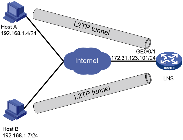
As shown in Figure 1, Host A and Host B in different areas transmit data through L2TP tunnels. Configure the network to meet the following requirements:
· Create two domains on the LNS to provide access services for users in different areas.
· Users in different domains obtain IP addresses from different subnets for communication with the LNS.
Analysis
For valid users to access normally and establish an L2TP tunnel in client-Initiated mode, perform the following tasks:
1. Configure L2TP user-side authentication on the LNS.
2. Create PPP users and their domains.
3. On the host side, initiate the tunnel setup requests on hosts by using the username configured on the device.
Software versions used
This configuration example was created and verified on R9141P16 of the MSR2630E-X1 device.
Procedures
Configuring the LNS
# Enable L2TP.
<LNS> system-view
[LNS] l2tp enable
# Configure two address pools, which are used to allocate IP addresses on different subnets to users in different domains.
[LNS] ip pool 1 10.0.1.2 10.0.1.10
[LNS] ip pool 2 10.0.2.2 10.0.2.10
# Configure domain abc.com to authorize address pool 1, and configure the domain to perform local authentication for PPP users.
[LNS] domain abc.com
[LNS-isp-abc.com] authorization-attribute ip-pool 1
[LNS-isp-abc.com] authentication ppp local
[LNS-isp-abc.com] quit
# Configure domain abc2.com to authorize address pool 2, and configure the domain to perform local authentication for PPP users.
[LNS] domain abc2.com
[LNS-isp-abc2.com] authorization-attribute ip-pool 2
[LNS-isp-abc2.com] authentication ppp local
[LNS-isp-abc2.com] quit
# Create VT interface 1, and assign IP address 10.0.1.1/24 to the VT interface. Configure the PPP authentication method as CHAP on the VT interface, and specify the VT interface to allocate IP addresses from address pool 1 to PPP users.
[LNS] interface virtual-template1
[LNS-Virtual-Template1] ppp authentication-mode chap domain abc.com
[LNS-Virtual-Template1] remote address pool 1
[LNS-Virtual-Template1] ip address 10.0.1.1 255.255.255.0
[LNS-Virtual-Template1] quit
# Create VT interface 2, and assign IP address 10.0.2.1/24 to the VT interface. Configure the PPP authentication method as CHAP on the VT interface, and specify the VT interface to allocate IP addresses from address pool 2 to PPP users.
[LNS] interface virtual-template2
[LNS-Virtual-Template2] ppp authentication-mode chap domain abc2.com
[LNS-Virtual-Template2] remote address pool 2
[LNS-Virtual-Template2] ip address 10.0.2.1 255.255.255.0
[LNS-Virtual-Template2] quit
# Configure interface GigabitEthernet 1/0/1.
[LNS] interface gigabitethernet 0/0/1
[LNS-GigabitEthernet1/0/1] port link-mode route
[LNS-GigabitEthernet1/0/1] ip address 172.31.123.101 255.255.255.0
[LNS-GigabitEthernet1/0/1] quit
# Create user user1. Set the password to hello and service type to PPP.
[LNS] local-user user1 class network
[LNS-luser-network-user1] password simple hello
[LNS-luser-network-user1] service-type ppp
[LNS-luser-network-user1] quit
# Create user user2. Set the password to hello and service type to PPP.
[LNS] local-user user2 class network
[LNS-luser-network-user2] password simple hello
[LNS-luser-network-user2] service-type ppp
[LNS-luser-network-user2] quit
# Create an L2TP group in LNS mode, and disable tunnel authentication.
[LNS] l2tp-group 1 mode lns
[LNS-l2tp1] allow l2tp virtual-template 1 remote user1.abc.com
[LNS-l2tp1] undo tunnel authentication
[LNS-l2tp1] quit
# Create an L2TP group in LNS mode, and disable tunnel authentication.
[LNS] l2tp-group 2 mode lns
[LNS-l2tp2] allow l2tp virtual-template 2 remote user2.abc2.com
[LNS-l2tp2] undo tunnel authentication
[LNS-l2tp2] quit
Configuring hosts
# Assign IP addresses 192.168.1.4 and 192.168.2.7 to the two hosts separately, and configure the gateways of the two hosts as their respective gateway addresses.
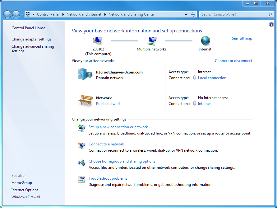
# Use Windows 7 as an example. Access Network and Sharing Center and click Set up a new connection or network.
Figure 2 Creating a network connection
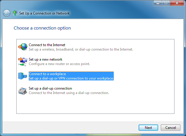
# Select Connect to a workspace and click Next.
Figure 3 Selecting a connection option
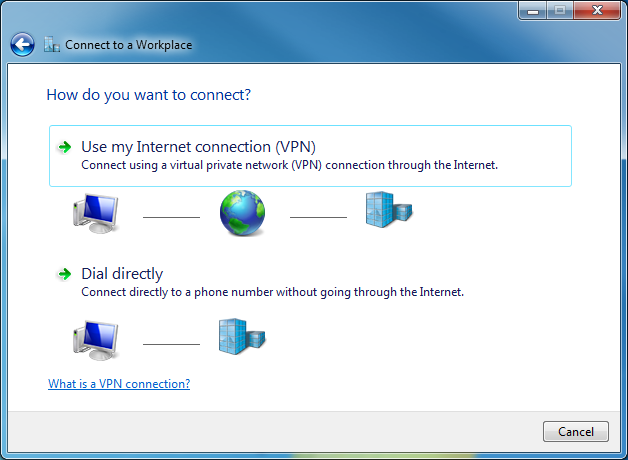
# Select Use my Internet connection(VPN).
Figure 4 Selecting a connection method
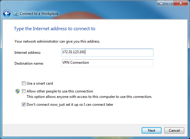
# Set the Internet address, which is the address of the host-side interface on the LNS. Select the Don't connect now; just set it up so I can connect later option, and click Next.
Figure 5 Setting the LNS address
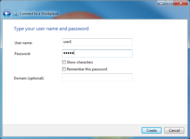
# In the diaglog box that opens, enter the username and password that have been configured on the device, and select Create.
Figure 6 Entering the username and password
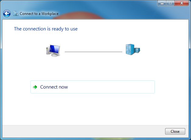
# At this point, the connection is available. Click Close.
Figure 7 Connection established successfully
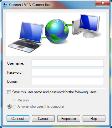
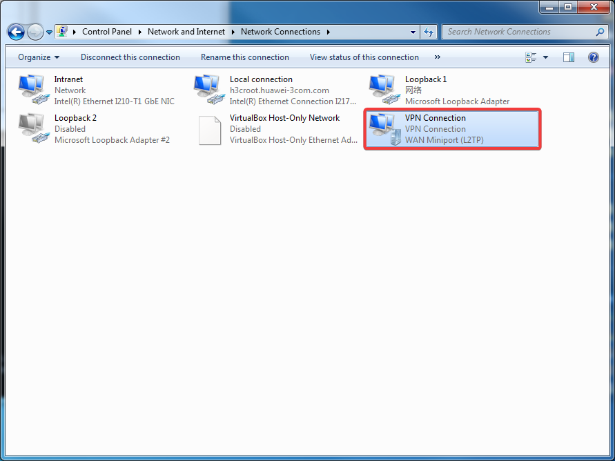
# Access the network connection page again, and you can see a new network connection named VPN Connection. Double-click it. The login window opens.
Figure 8 Newly generated connection
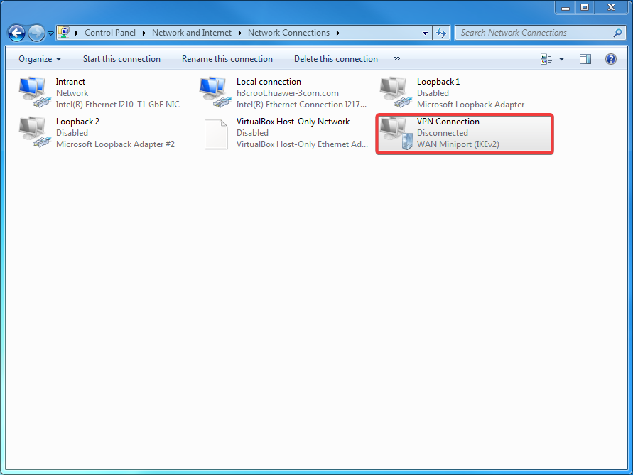
Figure 9 Login window
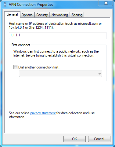
# Right-click the connection, and select Properties. The Properties dialog box opens.
Figure 10 VPN connection properties
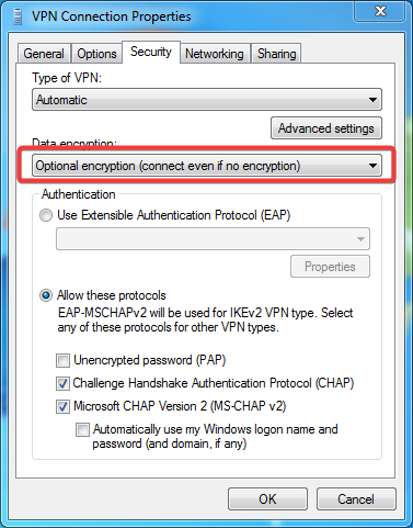
# Click the Security tab. Select Optional encryption (connect even if no encryption) for data encryption and click OK.
Figure 11 Configuring security properties
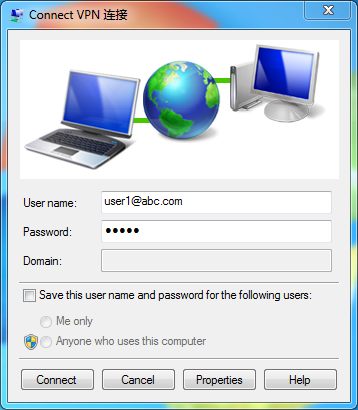
# On the login window, enter username [email protected] and password hello configured on the router, and click Connect.
Figure 12 Connecting an L2TP tunnel
# Verify that the connection succeeded.
Figure 13 Connection succeeded
Verifying the configuration
# On the LNS, execute the display l2tp tunnel command to view the established L2TP tunnels.
[LNS] display l2tp tunnel
LocalTID RemoteTID State Sessions RemoteAddress RemotePort RemoteName
23287 1 Established 1 192.168.1.4 1701 user1.abc.com
36956 35 Established 1 192.168.2.7 1701 user2.abc2.com
# On the LNS, execute the display l2tp session command to display the established L2TP sessions.
[LNS] display l2tp session
LocalSID RemoteSID LocalTID State
30933 1 23287 Established
21828 1 36956 Established
Configuration files
#
ip pool 1 10.0.1.2 10.0.1.10
ip pool 2 10.0.2.2 10.0.2.10
#
interface Virtual-Template1
ppp authentication-mode chap domain abc.com
remote address pool 1
ip address 10.0.1.1 255.255.255.0
#
interface Virtual-Template2
ppp authentication-mode chap domain abc2.com
remote address pool 2
ip address 10.0.2.1 255.255.255.0
#
interface GigabitEthernet1/0/1
port link-mode route
ip address 172.31.123.101 255.255.255.0
#
domain abc.com
authorization-attribute ip-pool 1
authentication ppp local
#
domain abc2.com
authorization-attribute ip-pool 2
authentication ppp local
#
user-group system
#
local-user user1 class network
password cipher $c$3$UkOKC65RHN4wUaJ6sWyzHKC7a+N59kEJ
service-type ppp
authorization-attribute user-role network-operator
#
local-user user2 class network
password cipher $c$3$JUujxfCIpEGTGw9HbO26xfm55GLo2g==
service-type ppp
authorization-attribute user-role network-operator
#
l2tp-group 1 mode lns
allow l2tp virtual-template 1 remote user1.abc.com
undo tunnel authentication
#
l2tp-group 2 mode lns
allow l2tp virtual-template 2 remote user2.abc2.com
undo tunnel authentication
#
l2tp enable
#
Related documentation
· Layer 2—WAN Access Configuration Guide in H3C MSR1000[2600][3600] Routers Configuration Guides (V9)
· Layer 2—WAN Access Command Reference in H3C MSR1000[2600][3600] Routers Command References (V9)