- Table of Contents
-
- H3C MSR1000[2600][3600] Routers Configuration Examples All-in-One-R9141-6W100
- 00-Preface
- 01-Local 802.1X Authentication Configuration Examples
- 02-RADIUS-Based 802.1X Authentication Configuration Examples
- 03-AAA Configuration Examples
- 04-ACL Configuration Examples
- 05-MPLS over ADVPN Configuration Examples
- 06-ARP Attack Protection Configuration Examples
- 07-BFD Configuration Examples
- 08-Basic BGP Configuration Examples
- 09-BGP Route Attribute-Based Route Selection Configuration Examples
- 10-EAA Monitor Policy Configuration Examples
- 11-GRE with OSPF Configuration Examples
- 12-HoVPN Configuration Examples
- 13-IGMP Snooping Configuration Examples
- 14-IGMP Configuration Examples
- 15-IPsec Configuration Examples
- 16-IPsec Digital Certificate Authentication Configuration Examples
- 17-IPv6 IS-IS Configuration Examples
- 18-IPv6 over IPv4 GRE Tunnel Configuration Examples
- 19-IPv6 over IPv4 Manual Tunnel with OSPFv3 Configuration Examples
- 20-IS-IS Configuration Examples
- 21-Combined ISATAP Tunnel and 6to4 Tunnel Configuration Examples
- 22-L2TP over IPsec Configuration Examples
- 23-Multi-Instance L2TP Configuration Examples
- 24-L2TP Multidomain Access Configuration Examples
- 25-MPLS L3VPN Configuration Examples
- 26-MPLS OAM Configuration Examples
- 27-MPLS TE Configuration Examples
- 28-Basic MPLS Configuration Examples
- 29-NAT DNS Mapping Configuration Examples
- 30-NetStream Configuration Examples
- 31-NQA Configuration Examples
- 32-NTP Configuration Examples
- 33-OSPFv3 Configuration Examples
- 34-OSPF Configuration Examples
- 35-OSPF Multi-Process Configuration Examples
- 36-OSPF Multi-Instance Configuration Examples
- 37-Portal Configuration Examples
- 38-PPP Configuration Examples
- 39-RBAC Configuration Examples
- 40-RMON Configuration Examples
- 41-IPv4 NetStream Sampling Configuration Examples
- 42-SNMP Configuration Examples
- 43-SRv6 Configuration Examples
- 44-SSH Configuration Examples
- 45-Tcl Commands Configuration Examples
- 46-VLAN Configuration Examples
- 47-VRRP Configuration Examples
- 48-VXLAN over IPsec Configuration Examples
- 49-WLAN AC Configuration Examples
- 50-Small and Medium-Sized Store Configuration Examples
- 51-Cloudnet VPN Configuration Examples
- 52-Ethernet Link Aggregation Configuration Examples
- 53-Ethernet OAM Configuration Examples
- 54-Outbound Bidirectional NAT Configuration Examples
- 55-NAT Hairpin in C-S Mode Configuration Examples
- 56-Load Sharing NAT Server Configuration Examples
- 57-BIDIR-PIM Configuration Examples
- 58-Control Plane-Based QoS Policy Configuration Examples
- 59-Scheduling a Task Configuration Examples
- 60-Client-Initiated L2TP Tunnel Configuration Examples
- 61-LAC-Auto-Initiated L2TP Tunnel Configuration Examples
- 62-Authorized ARP Configuration Examples
- 63-GTS Configuration Examples
- 64-Traffic Policing Configuration Examples
- 65-Traffic Accounting Configuration Examples
- 66-Mobile Communication Modem Management Configuration Examples
- 67-Port Isolation Configuration Examples
- 68-PBR Configuration Examples
- 69-TFTP Client Software Upgrade Configuration Examples
- 70-FTP Client Software Upgrade Configuration Examples
- 71-FTP Server Software Upgrade Configuration Examples
- 72-Routing Policy Configuration Examples
- 73-Software Upgrade from the BootWare Menu Configuration Examples
- 74-Mirroring Configuration Examples
- Related Documents
-
| Title | Size | Download |
|---|---|---|
| 50-Small and Medium-Sized Store Configuration Examples | 277.20 KB |
H3C Routers
Small and Medium-Sized Store Configuration Examples
Copyright © 2024 New H3C Technologies Co., Ltd. All rights reserved.
No part of this manual may be reproduced or transmitted in any form or by any means without prior written consent of Hangzhou H3C Technologies Co., Ltd.
Except for the trademarks of New H3C Technologies Co., Ltd., any trademarks that may be mentioned in this document are the property of their respective owners.
The information in this document is subject to change without notice.
Introduction
The following information provides an example for using a router in small- to medium-sized store networking.
Prerequisites
The following information applies to Comware 9-based routers. Procedures and information in the examples might be slightly different depending on the software or hardware version of the router.
The configuration examples were created and verified in a lab environment, and all the devices were started with the factory default configuration. When you are working on a live network, make sure you understand the potential impact of every command on your network.
The following information is provided based on the assumption that you have basic knowledge of DHCP, WLAN, PPPoE, and NAT.
Example: Configuring router settings for small and medium-sized store networking
Network configuration
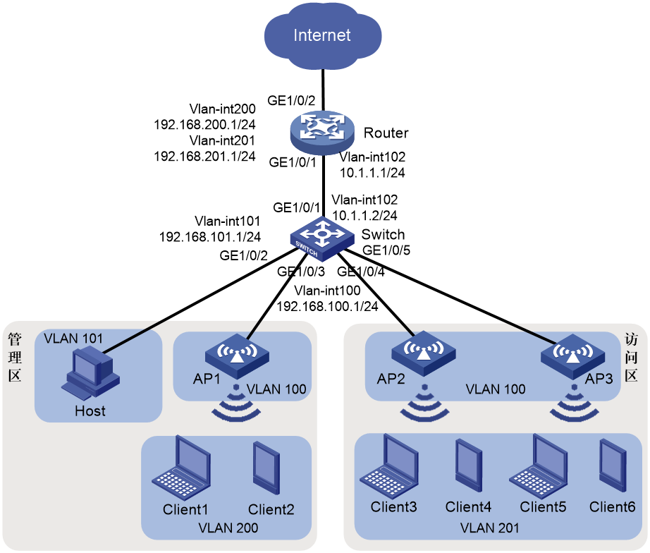
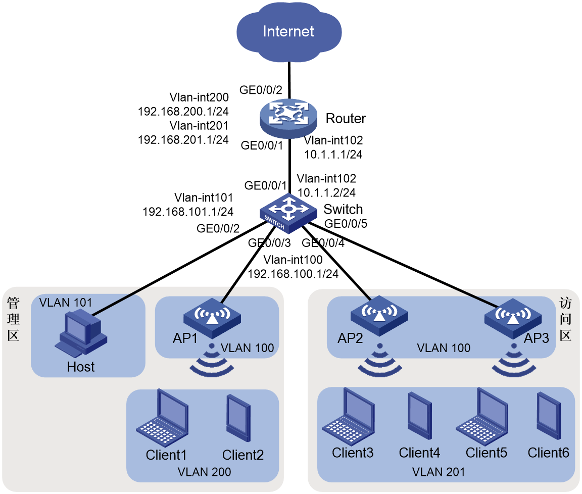
As shown in Figure 1, the networking requirements for a small to medium-sized store are as follows:
· The router acts as a DHCP server, allocating IP addresses to APs, wireless clients, and wired hosts.
· Users in the administration zone can access the Internet through wired and wireless connections. Wireless users in the zone access the WLAN using the PSK authentication and key management mode.
· The router acts as both the portal authentication server and portal Web server. It offers wireless users in the access zone a direct method for portal authentication to access the Internet.
· The router acts as the exit gateway for Internet access through PPPoE dial-up. It must support NAT for private network address translation.
![]()
![]()
![]()
![]()
![]()
![]()
1. Terminal VLAN and address pool resource planning
|
Device |
Corresponding VLAN |
DHCP address pool and network segment |
|
AP |
100 |
1: 192.168.100.0/24 |
|
Wireless clients in the administration zone |
200 |
2: 192.168.200.0/24 |
|
Wired terminals in the administration zone |
101 |
3: 192.168.101.0/24 |
|
Wireless clients in the access zone |
201 |
4: 192.168.201.0/24 |
Software versions used
This configuration example was created and verified on R9141P16 of the MSR2630E-X1 router.
Analysis
· On the router, configure the AP to obtain the IP address of the AC through Option 43 carried in the DHCP response to complete Layer 3 registration.
· Configure the wireless AC server on the router to ensure that wireless clients can access the network through the configured wireless service.
· Configure direct portal authentication service on the router for users to enter a username and password to complete portal authentication before accessing the network.
· Configure route settings between routers, switches, and APs to enable network interoperability.
Restrictions and guidelines
Use the serial ID labeled on the AP's rear panel to specify an AP.
Procedures
Configuring the router
Configuring the DHCP server
# Enable the DHCP service.
<Router> system-view
[Router] dhcp enable
# Create VLAN 102 and VLAN-interface 102, and configure an IP address for the interface. The AP will obtain the IP address to establish a CAPWAP tunnel with the AC.
[Router] vlan 102
[Router-vlan102] quit
[Router] interface Vlan-interface 102
[Router-Vlan-interface102] ip address 10.1.1.1 24
# Configure VLAN-interface 102 to operate in DHCP server mode.
[Router-Vlan-interface102] dhcp select server
[Router-Vlan-interface102] quit
# Configure GigabitEthernet 0/0/1 as a trunk port, and configure the interface to allow VLAN 102 to pass.
[Router] interface gigabitethernet 0/0/1
[Router-GigabitEthernet0/0/1] port link-mode bridge
[Router-GigabitEthernet0/0/1] port link-type trunk
[Router-GigabitEthernet0/0/1] port trunk permit vlan 102
[Router-GigabitEthernet0/0/1] quit
# Create VLANs 200 and 201 for wireless clients to access the wireless network. Configure the IP addresses for VLAN-interface 200 and VLAN-interface 201.
[Router] vlan 200
[Router-vlan200] quit
[Router] interface vlan-interface 200
[Router-Vlan-interface101] ip address 192.168.200.1 24
[Router-Vlan-interface101] quit
[Router] vlan 201
[Router-vlan201] quit
[Router] interface vlan-interface 201
[Router-Vlan-interface201] ip address 192.168.201.1 24
[Router-Vlan-interface201] quit
# Configure DHCP address pool 1 to allocate addresses in subnet 192.168.100.0/24 for APs, with the gateway address set to 192.168.100.1.
[Router] dhcp server ip-pool 1
[Router-dhcp-pool-1] network 192.168.100.0 mask 255.255.255.0
[Router-dhcp-pool-1] gateway-list 192.168.100.1
# Specify the hexadecimal IP address of the router as the content of DHCP Option 43.
[Router-dhcp-pool-1] option 43 hex 80070000010a010101
[Router-dhcp-pool-1] quit
# Configure DHCP address pool 2 to allocate addresses in subnet 192.168.200.0/24 for wireless clients in the administration zone, with the gateway address set to 192.168.200.1.
[Router] dhcp server ip-pool 2
[Router-dhcp-pool-2] network 192.168.200.0 mask 255.255.255.0
[Router-dhcp-pool-2] gateway-list 192.168.200.1
[Router-dhcp-pool-2] quit
# Configure DHCP address pool 3 to allocate addresses in subnet 192.168.101.0/24 for wired terminals in the administration zone, with the gateway address set to 192.168.101.1.
[Router] dhcp server ip-pool 3
[Router-dhcp-pool-3] network 192.168.101.0 mask 255.255.255.0
[Router-dhcp-pool-3] gateway-list 192.168.101.1
[Router-dhcp-pool-3] quit
# Configure DHCP address pool 4 to allocate addresses in subnet 192.168.201.0/24 for wireless clients in the access zone, with the gateway address set to 192.168.201.1.
[Router] dhcp server ip-pool 4
[Router-dhcp-pool-4] network 192.168.201.0 mask 255.255.255.0
[Router-dhcp-pool-4] gateway-list 192.168.201.1
[Router-dhcp-pool-4] quit
# Configure static routes to each client network segment.
[Router] ip route-static 192.168.100.0 24 10.1.1.2
[Router] ip route-static 192.168.101.0 24 10.1.1.2
Configuring the AC
Table 1 Configure wireless service 1 for the administration zone
# Create wireless service template 1 and enter its view.
[Router] wlan service-template 1
# Set the SSID to employee.
[Router-wlan-st-1] ssid employee
# Specify the authentication and key management mode as PSK and set the PSK key to plaintext string 12345678.
[Router-wlan-st-1] akm mode psk
[Router-wlan-st-1] preshared-key pass-phrase simple 12345678
# Specify the cipher suite as CCMP and the security IE as RSN.
[Router-wlan-st-1] cipher-suite ccmp
[Router-wlan-st-1] security-ie rsn
# Specify the AC as the client data forwarder. You can skip this step if the AC is the default client data forwarder.
[Router-wlan-st-1] client forwarding-location ac
# Enable wireless service template 1.
[Router–wlan-st-1] service-template enable
[Router-wlan-st-1] quit
Table 2 Configure service template 2 for the access zone
# Create wireless service template 2 and enter its view.
[Router] wlan service-template 2
# Set the SSID to guest.
[Router-wlan-st-2] ssid guest
# Specify the AC as the client data forwarder. You can skip this step if the AC is the default client data forwarder.
[Router-wlan-st-1] client forwarding-location ac
# Enable wireless service template 2.
[Router–wlan-st-2] service-template enable
[Router-wlan-st-2] quit
Table 3 Configure the AP in the administrator zone
# Create an AP named ap1 and specify the AP model.
[Router] wlan ap ap1 model WA4320H
# Set the AP serial number to 219801A0YG819BE005JC.
[Router-wlan-ap-ap1] serial-id 219801A0YG819BE005JC
# Enter radio view of radio 1 on AP ap1, bind wireless service template 1 to radio 1, and configure clients coming online from the radio to join VLAN 200.
[Router-wlan-ap-ap1] radio 1
[Router-wlan-ap-ap1-radio-1] service-template 1 vlan 200
# Enable radio 1.
[Router-wlan-ap-ap1-radio-1] radio enable
[Router-wlan-ap-ap1-radio-1] return
Table 4 Configure the AP group for the access zone
# Create AP ap2 and AP ap3, and specify the AP models and serial numbers.
<Router> system-view
[Router] wlan ap ap2 model WA4320H
[Router-wlan-ap-ap2] serial-id 219801A0YG8198E0064J
[Router-wlan-ap-ap2] quit
[Router] wlan ap ap3 model WA4320H
[Router-wlan-ap-ap3] serial-id 219801A0YG8198E0078C
[Router-wlan-ap-ap3] quit
# Create AP group group1 and add APs ap2 and ap3 to the group.
[Router] wlan ap-group group1
[Router-wlan-ap-group-group1] ap ap2 ap3
# Bind wireless service template 2 to radio 2 on APs in AP group group1, and configure clients coming online from the radio to join VLAN 201.
[Router-wlan-ap-group-group1] ap-model WA4320H
[Router-wlan-ap-group-group1-ap-model-WA4320H] radio 2
[Router-wlan-ap-group-group1-ap-model-WA4320H-radio-2] service-template 2 vlan 201
# Enable radio 1.
[Router-wlan-ap-group-group1-ap-model-WA4320H-radio-2] radio enable
[Router-wlan-ap-group-group1-ap-model-WA4320H-radio-2] return
Configuring the portal authentication server and portal Web server
Table 1 Configuring AAA
# Create an ISP domain named dm1 and enter its view.
<Router> system-view
[Router] domain dm1
# Set the AAA authentication method to local for portal users.
[Router-isp-dm1] authentication portal local
# Set the AAA authorization method for portal users to none.
[Router-isp-dm1] authorization portal none
# Set the AAA accounting method for portal users to none.
[Router-isp-dm1] accounting portal none
Set the idle timeout for users in the ISP domain dm1 to 15 minutes and the minimum traffic to 1024 bytes.
[Router-isp-dm1] authorization-attribute idle-cut 15 1024
[Router-isp-dm1] quit
Table 2 Configure portal authentication
# Specify the URL of the portal Web server as http://192.168.201.1/portal.
[Router] portal web-server newpt
[Router-portal-websvr-newpt] url http://192.168.201.1/portal
[Router-portal-websvr-newpt] quit
# Configure two destination-based portal authentication-free rules to allow traffic to the DNS server.
[Router] portal free-rule 1 destination ip any udp 53
[Router] portal free-rule 2 destination ip any tcp 53
# Enable direct portal authentication on wireless service template 2.
[Router] wlan service-template 2
[Router–wlan-st-2] portal enable method direct
# Apply portal Web server newpt to wireless service template 2.
[Router–wlan-st-2] portal apply web-server newpt
[Router–wlan-st-2] quit
# Create an HTTP-based local portal Web service and enter its view.
[Router] portal local-web-server http
# Configure the local portal Web server to use the default authentication paging file bendi.zip. Make sure the file already exist in the root directory of the device storage media.
[Router–portal-local-websvr-http] default-logon-page bendi.zip
[Router–portal-local-websvr-http] quit
# Configure the username and password for local portal authentication.
[Router] local-user guest class network
[Router-luser-network-guest] password simple abc123
[Router-luser-network-guest] service-type portal
[Router-luser-network-guest] quit
# Enable intra-VLAN roaming for portal users.
[Router] portal roaming enable
# Disable the Rule ARP entry feature for portal clients.
[Router] undo portal refresh arp enable
# Enable validity check on wireless portal clients.
[Router] portal host-check enable
Configuring PPPoE dial-up for Internet access
# Create dialer group 1.
[Router] dialer-group 1 rule ip permit
# Create a dialer interface, and configure dialer parameters, IP address negotiation, and PAP authentication.
[Router] interface dialer 0
[Router-Dialer0] dialer bundle enable
[Router-Dialer0] dialer-group 1
[Router-Dialer0] ip address ppp-negotiate
[Router-Dialer0] ppp pap local-user aaa password simple abc123
[Router-Dialer0] quit
# Configure a PPPoE session corresponding to Dialer bundle 1 on GigabitEthernet 0/0/2.
[Router] interface gigabitethernet 0/0/2
[Router-GigabitEthernet0/0/2] pppoe-client dial-bundle-number 1
[Router-GigabitEthernet0/0/2] quit
Configuring NAT
# Configure NAT.
[Router] interface dialer 0
[Router-Dialer0] nat outbound
[Router-Dialer0] quit
# Configure a default static route with egress interface Dialer0.
[Router] ip route-static 0.0.0.0 0 Dialer0
[Router] quit
Configuring the switch
Table 3 Configure VLANs and VLAN interfaces.
<Sysname> system-view
[Switch] vlan 100
[Switch-vlan100] quit
[Switch] interface vlan-interface 100
[Switch-Vlan-interface100] ip address 192.168.100.1 24
[Switch-Vlan-interface100] quit
[Switch] vlan 101
[Switch] interface vlan-interface 101
[Switch-Vlan-interface101] ip address 192.168.101.1 24
[Switch-Vlan-interface101] quit
[Switch] vlan 102
[Switch-vlan102] quit
[Switch] interface vlan-interface 102
[Switch-Vlan-interface102] ip address 10.1.1.2 24
[Switch-Vlan-interface102] quit
Table 4 Configure GigabitEthernet 0/0/1 connecting the switch to the router as a trunk port and allow VLAN 102 to pass.
[Switch] interface gigabitethernet 0/0/1
[Switch-GigabitEthernet0/0/1] port link-type trunk
[Switch-GigabitEthernet0/0/1] port trunk permit vlan 102
[Switch-GigabitEthernet0/0/1] quit
Table 5 Configure GigabitEthernet 0/0/2 connecting the switch to wired terminals in the administration zone as an access port and add the port to VLAN 101.
[Switch] interface gigabitethernet 0/0/2
[Switch-GigabitEthernet0/0/2] port link-type access
[Switch-GigabitEthernet0/0/2] port access vlan 101
[Switch-GigabitEthernet0/0/2] quit
Table 6 # Configure GigabitEthernet 0/0/3 connecting the switch to APs in the administration zone as a trunk port, block VLAN 1, and allow VLAN 100 to pass.
[Switch] interface gigabitethernet 0/0/3
[Switch-GigabitEthernet0/0/3] port link-type trunk
[Switch-GigabitEthernet0/0/3] undo port trunk permit vlan 1
[Switch-GigabitEthernet0/0/3] port trunk permit vlan 100
[Switch-GigabitEthernet0/0/3] port trunk pvid vlan 100
[Switch-GigabitEthernet0/0/3] quit
Table 7 Configure GigabitEthernet 0/0/4 and GigabitEthernet 0/0/5 as trunk ports, block VLAN 1, and allow VLAN 100 to pass.
[Switch] interface gigabitethernet 0/0/4
[Switch-GigabitEthernet0/0/4] port link-type trunk
[Switch-GigabitEthernet0/0/4] undo port trunk permit vlan 1
[Switch-GigabitEthernet0/0/4] port trunk permit vlan 100
[Switch-GigabitEthernet0/0/4] port trunk pvid vlan 100
[Switch-GigabitEthernet0/0/4] quit
[Switch] interface gigabitethernet 0/0/5
[Switch-GigabitEthernet0/0/5] port link-type trunk
[Switch-GigabitEthernet0/0/5] undo port trunk permit vlan 1
[Switch-GigabitEthernet0/0/5] port trunk permit vlan 100
[Switch-GigabitEthernet0/0/5] port trunk pvid vlan 100
[Switch-GigabitEthernet0/0/5] quit
Table 8 Configure the switch to act as a DHCP relay and specify IP address 10.1.1.1 of the router as the DHCP server address.
[Switch] dhcp enable
[Switch] interface vlan-interface 100
[Switch-Vlan-interface100] dhcp select relay
[Switch-Vlan-interface100] dhcp relay server-address 10.1.1.1
[Switch-Vlan-interface100] quit
[Switch] interface vlan-interface 101
[Switch-Vlan-interface101] dhcp select relay
[Switch-Vlan-interface101] dhcp relay server-address 10.1.1.1
[Switch-Vlan-interface101] quit
Table 9 Configure a default route.
[Switch] ip route-static 0.0.0.0 0 10.1.1.1
Verifying the configuration
Table 1 View the IP address allocation information for the address pool on the router.
<Router> display dhcp server ip-in-use
IP address Client identifier/ Lease expiration Type
Hardware address
192.168.100.2 0194-292f-9314-c0 Sep 2 15:32:28 2022 Auto(C)
192.168.100.3 0154-2bde-fd4b-a0 Sep 2 15:32:30 2022 Auto(C)
192.168.100.4 0102-6121-250c-0e Sep 2 15:32:30 2022 Auto(C)
192.168.101.2 0035-6361-352e-6339- Sep 2 15:58:42 2022 Auto(C)
6330-2e30-3330-362d-
4745-302f-302f-31
192.168.200.2 018e-7170-24dd-21 Sep 2 15:45:13 2022 Auto(C)
192.168.201.2 011a-95ad-b5a7-08 Sep 2 15:44:57 2022 Auto(C)
192.168.201.3 0112-2016-7f1b-01 Sep 2 15:44:16 2022 Auto(C)
Table 2 View the AP registration information on the AC.
# Verify that the AP state is R/M, which indicates that the AP has been successfully registered with the AC.
<Router> display wlan ap all
Total number of APs: 3
Total number of connected APs: 3
Total number of connected manual APs: 3
Total number of connected auto APs: 0
Total number of connected common APs: 3
Total number of connected WTUs: 0
Total number of inside APs: 0
Maximum supported APs: 16
Remaining APs: 13
Total AP licenses: 128
Local AP licenses: 128
Server AP licenses: 0
Remaining Local AP licenses: 125
Sync AP licenses: 0
AP information
State : I = Idle, J = Join, JA = JoinAck, IL = ImageLoad
C = Config, DC = DataCheck, R = Run, M = Master, B = Backup
AP name APID State Model Serial ID
ap1 1 R/M WA4320H 219801A0YG819BE005JC
ap2 2 R/M WA4320H 219801A0YG8198E0064J
ap3 3 R/M WA4320H 219801A0YG8198E0078C
Table 3 View client information on the AC.
# Verify that the client has come online from radio 1.
<Router> display wlan client
Total number of clients: 3
MAC address User name AP name R IP address VLAN
8e71-7024-dd21 N/A ap1 1 192.168.200.2 200
1a95-adb5-a708 N/A ap2 2 192.168.201.2 201
1220-167f-1b01 N/A ap2 2 192.168.201.3 201
Table 4 Verify that the wireless client has obtained an IP address and come online.
Use a wireless client in the administration zone as an example:
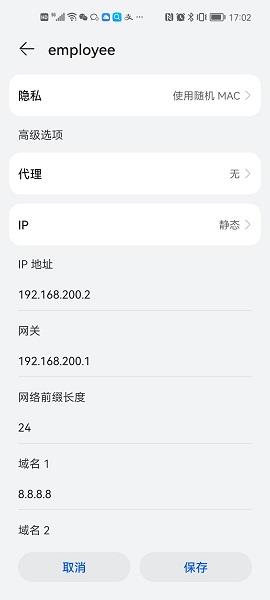
Table 5 Verify that users in the access zone can perform portal authentication through a Web page. Before authentication, all web access initiated by a user is redirected to the portal authentication page (http://192.168.201.1/portal), as shown in the figure below:

A user must enter the username and password manually at the first-time portal authentication. For subsequent network access, the user can directly access Internet resources without noticing the portal authentication process.
View the information about online portal users generated on the router.
<Router> display portal user all
Total portal users: 2
Username: guest
AP name: ap2
Radio ID: 2
SSID: guest
Portal server: N/A
State: Online
VPN instance: N/A
MAC IP VLAN Interface
1a95-adb5-a708 192.168.201.2 201 WLAN-BSS0/4
Authorization information:
DHCP IP pool: N/A
User profile: N/A
Session group profile: N/A
ACL number/name: N/A
Inbound CAR: N/A
Outbound CAR: N/A
Username: guest
AP name: ap2
Radio ID: 2
SSID: guest
Portal server: N/A
State: Online
VPN instance: N/A
MAC IP VLAN Interface
1220-167f-1b01 192.168.201.3 201 WLAN-BSS0/4
Authorization information:
DHCP IP pool: N/A
User profile: N/A
Session group profile: N/A
ACL number/name: N/A
Inbound CAR: N/A
Outbound CAR: N/A
Configuration files
· Router
#
dhcp enable
#
vlan 102
#
vlan 200 to 201
#
dhcp server ip-pool 1
gateway-list 192.168.100.1
network 192.168.100.0 mask 255.255.255.0
option 43 hex 80070000010a010101
#
dhcp server ip-pool 2
gateway-list 192.168.200.1
network 192.168.200.0 mask 255.255.255.0
#
dhcp server ip-pool 3
gateway-list 192.168.101.1
network 192.168.101.0 mask 255.255.255.0
#
dhcp server ip-pool 4
gateway-list 192.168.201.1
network 192.168.201.0 mask 255.255.255.0
#
wlan service-template 1
ssid employee
akm mode psk
preshared-key pass-phrase cipher $c$3$mczcUlpjginwHwJ3vABq97tR3kLdRI823mKv
cipher-suite ccmp
security-ie rsn
service-template enable
#
wlan service-template 2
ssid guest
portal enable method direct
portal apply web-server newpt
service-template enable
#
interface Dialer0
ppp pap local-user h3c password cipher $c$3$Z3pvO6H0my2Z6Yq5QfmoMO5SrTDn7A==
dialer bundle enable
dialer-group 1
ip address ppp-negotiate
nat outbound
#
interface Vlan-interface102
ip address 10.1.1.1 255.255.255.0
#
interface Vlan-interface200
ip address 192.168.200.1 255.255.255.0
#
interface Vlan-interface201
ip address 192.168.201.1 255.255.255.0
#
interface GigabitEthernet0/0/2
port link-mode route
pppoe-client dial-bundle-number 1
#
interface GigabitEthernet0/0/1
port link-mode bridge
port link-type trunk
port trunk permit vlan 102
#
ip route-static 0.0.0.0 0 Dialer0
ip route-static 192.168.100.0 24 10.1.1.2
ip route-static 192.168.101.0 24 10.1.1.2
#
domain dm1
authorization-attribute idle-cut 15 1024
authentication portal local
authorization portal none
accounting portal none
#
local-user guest class network
password cipher $c$3$N+s6HOuF0o1QxOe48Ly+kHVQrT21UBXNgA==
service-type portal
#
portal host-check enable
portal free-rule 1 destination ip any udp 53
portal free-rule 2 destination ip any tcp 53
#
portal web-server newpt
url http://192.168.201.1:8080/portal
#
portal local-web-server http
default-logon-page bendi.zip
#
wlan ap-group group1
wlan ap-group group1
vlan 1
ap ap2
ap ap3
ap-model WA4320H
radio 1
radio 2
radio enable
service-template 2 vlan 201
#
wlan ap ap1 model WA4320H
serial-id 219801A0YG819BE005JC
vlan 1
radio 1
radio enable
service-template 1 vlan 200
radio 2
#
wlan ap ap2 model WA4320H
serial-id 219801A0YG819BE0064J
vlan 1
radio 1
radio 2
#
wlan ap ap3 model WA4320H
serial-id 219801A0YG819BE0078C
vlan 1
radio 1
radio 2
#
· Switch
#
dhcp enable
#
vlan 100 to 102
#
interface Vlan-interface100
ip address 192.168.100.1 255.255.255.0
dhcp select relay
dhcp relay server-address 10.1.1.1
#
interface Vlan-interface101
ip address 192.168.101.1 255.255.255.0
dhcp select relay
dhcp relay server-address 10.1.1.1
#
interface Vlan-interface102
ip address 10.1.1.2 255.255.255.0
#
interface GigabitEthernet0/0/1
port link-mode bridge
port link-type trunk
port trunk permit vlan 102
#
interface GigabitEthernet0/0/2
port link-mode bridge
port access vlan 101
#
interface GigabitEthernet0/0/3
port link-mode bridge
port link-type trunk
undo port trunk permit vlan 1
port trunk permit vlan 100
port trunk pvid vlan 100
#
interface GigabitEthernet0/0/4
port link-mode bridge
port link-type trunk
undo port trunk permit vlan 1
port trunk permit vlan 100
port trunk pvid vlan 100
#
interface GigabitEthernet0/3
port link-mode bridge
port link-type trunk
undo port trunk permit vlan 1
port trunk permit vlan 100
port trunk pvid vlan 100
#
ip route-static 0.0.0.0 0 10.1.1.1
#