- Table of Contents
-
- H3C MSR1000[2600][3600] Routers Configuration Examples All-in-One-R9141-6W100
- 00-Preface
- 01-Local 802.1X Authentication Configuration Examples
- 02-RADIUS-Based 802.1X Authentication Configuration Examples
- 03-AAA Configuration Examples
- 04-ACL Configuration Examples
- 05-MPLS over ADVPN Configuration Examples
- 06-ARP Attack Protection Configuration Examples
- 07-BFD Configuration Examples
- 08-Basic BGP Configuration Examples
- 09-BGP Route Attribute-Based Route Selection Configuration Examples
- 10-EAA Monitor Policy Configuration Examples
- 11-GRE with OSPF Configuration Examples
- 12-HoVPN Configuration Examples
- 13-IGMP Snooping Configuration Examples
- 14-IGMP Configuration Examples
- 15-IPsec Configuration Examples
- 16-IPsec Digital Certificate Authentication Configuration Examples
- 17-IPv6 IS-IS Configuration Examples
- 18-IPv6 over IPv4 GRE Tunnel Configuration Examples
- 19-IPv6 over IPv4 Manual Tunnel with OSPFv3 Configuration Examples
- 20-IS-IS Configuration Examples
- 21-Combined ISATAP Tunnel and 6to4 Tunnel Configuration Examples
- 22-L2TP over IPsec Configuration Examples
- 23-Multi-Instance L2TP Configuration Examples
- 24-L2TP Multidomain Access Configuration Examples
- 25-MPLS L3VPN Configuration Examples
- 26-MPLS OAM Configuration Examples
- 27-MPLS TE Configuration Examples
- 28-Basic MPLS Configuration Examples
- 29-NAT DNS Mapping Configuration Examples
- 30-NetStream Configuration Examples
- 31-NQA Configuration Examples
- 32-NTP Configuration Examples
- 33-OSPFv3 Configuration Examples
- 34-OSPF Configuration Examples
- 35-OSPF Multi-Process Configuration Examples
- 36-OSPF Multi-Instance Configuration Examples
- 37-Portal Configuration Examples
- 38-PPP Configuration Examples
- 39-RBAC Configuration Examples
- 40-RMON Configuration Examples
- 41-IPv4 NetStream Sampling Configuration Examples
- 42-SNMP Configuration Examples
- 43-SRv6 Configuration Examples
- 44-SSH Configuration Examples
- 45-Tcl Commands Configuration Examples
- 46-VLAN Configuration Examples
- 47-VRRP Configuration Examples
- 48-VXLAN over IPsec Configuration Examples
- 49-WLAN AC Configuration Examples
- 50-Small and Medium-Sized Store Configuration Examples
- 51-Cloudnet VPN Configuration Examples
- 52-Ethernet Link Aggregation Configuration Examples
- 53-Ethernet OAM Configuration Examples
- 54-Outbound Bidirectional NAT Configuration Examples
- 55-NAT Hairpin in C-S Mode Configuration Examples
- 56-Load Sharing NAT Server Configuration Examples
- 57-BIDIR-PIM Configuration Examples
- 58-Control Plane-Based QoS Policy Configuration Examples
- 59-Scheduling a Task Configuration Examples
- 60-Client-Initiated L2TP Tunnel Configuration Examples
- 61-LAC-Auto-Initiated L2TP Tunnel Configuration Examples
- 62-Authorized ARP Configuration Examples
- 63-GTS Configuration Examples
- 64-Traffic Policing Configuration Examples
- 65-Traffic Accounting Configuration Examples
- 66-Mobile Communication Modem Management Configuration Examples
- 67-Port Isolation Configuration Examples
- 68-PBR Configuration Examples
- 69-TFTP Client Software Upgrade Configuration Examples
- 70-FTP Client Software Upgrade Configuration Examples
- 71-FTP Server Software Upgrade Configuration Examples
- 72-Routing Policy Configuration Examples
- 73-Software Upgrade from the BootWare Menu Configuration Examples
- 74-Mirroring Configuration Examples
- Related Documents
-
| Title | Size | Download |
|---|---|---|
| 09-BGP Route Attribute-Based Route Selection Configuration Examples | 153.53 KB |
BGP Route Attribute-Based Route Selection Configuration Examples
Copyright © 2024 New H3C Technologies Co., Ltd. All rights reserved.
No part of this manual may be reproduced or transmitted in any form or by any means without prior written consent of New H3C Technologies Co., Ltd.
Except for the trademarks of New H3C Technologies Co., Ltd., any trademarks that may be mentioned in this document are the property of their respective owners.
The information in this document is subject to change without notice.
Contents
Example: Configuring route selection based on the AS_PATH attribute
Configuring IP addresses for interfaces
Example: Configuring route selection based on the MED attribute
Introduction
This document provides examples for configuring BGP route selection based on route attributes.
Prerequisites
The configuration examples in this document were created and verified in a lab environment, and all the devices were started with the factory default configuration. When you are working on a live network, make sure you understand the potential impact of every command on your network.
This document assumes that you have basic knowledge of BGP and routing policy.
Example: Configuring route selection based on the AS_PATH attribute
Network configuration
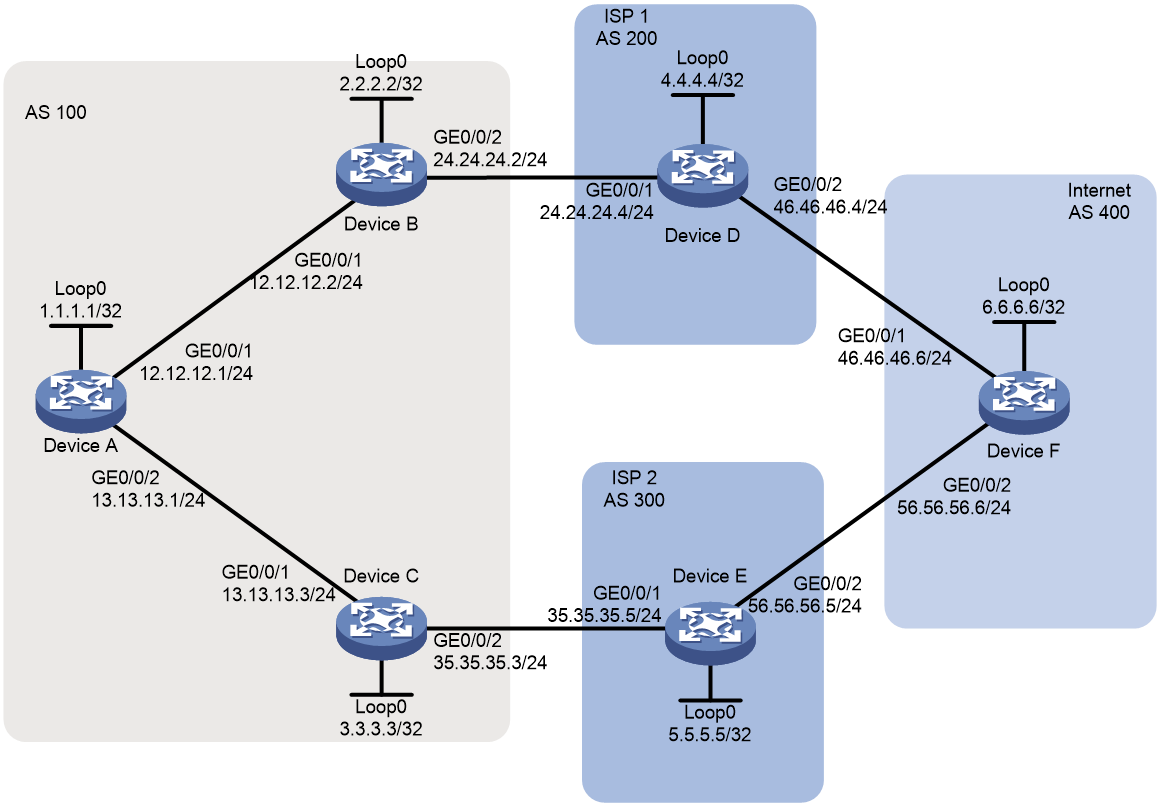
As shown in Figure 1, all devices run BGP. Two paths can be used for communication between AS 100 and AS 400. Path Device A > Device B > Device D > Device F passes through AS 200, and path Device A > Device C > Device E > Device F passes through AS 300. Configure a routing policy on Device B and Device C separately to meet the following requirements:
· Traffic from AS 100 to AS 200 is preferentially forwarded by Device D.
· Traffic from AS 100 to AS 300 is preferentially forwarded by Device E.
· Traffic from AS 100 to AS 400 is preferentially forwarded by Device D.
Analysis
· For devices in AS 100 to select the optimal route based on the first AS number in the AS_PATH attribute, the edge device in AS 100 must perform the following operations:
¡ Increases the local preference for routes sourced from the specified ASs.
¡ Advertises those routes inside AS 100.
To have the edge device perform the above operations:
¡ Configure a routing policy on Device B to set the local preference to 300 for routes sourced from AS 200 or 400.
¡ Configure a routing policy on Device C to set the local preference to 200 for routes sourced from AS 300.
· Use an AS path list to filter routes based on AS numbers.
Software versions used
This configuration example was created and verified on R9141P16 of the MSR2630E-X1 device.
Procedures
Configuring IP addresses for interfaces
# Configure an IP address for GigabitEthernet 1/0/1 on Device A.
<DeviceA> system-view
[DeviceA] interface gigabitethernet 1/0/1
[DeviceA-GigabitEthernet1/0/1] ip address 12.12.12.1 24
[DeviceA-GigabitEthernet1/0/1] quit
# Configure IP addresses for other interfaces as shown in Figure 1. (Details not shown.)
Configuring BGP connections
# On Device A, enable the default BGP instance, set the AS number to 100, and specify 12.12.12.2 and 13.13.13.3 as BGP peers.
[DeviceA] bgp 100
[DeviceA-bgp] router-id 1.1.1.1
[DeviceA-bgp] peer 12.12.12.2 as-number 100
[DeviceA-bgp] peer 13.13.13.3 as-number 100
[DeviceA-bgp] address-family ipv4 unicast
[DeviceA-bgp-ipv4] peer 12.12.12.2 enable
[DeviceA-bgp-ipv4] peer 13.13.13.3 enable
[DeviceA-bgp-ipv4] quit
[DeviceA-bgp] quit
# On Device B, enable the default BGP instance, set the AS number to 100, specify 12.12.12.1 and 24.24.24.4 as BGP peers, and redistribute direct routes.
[DeviceB] bgp 100
[DeviceB-bgp] router-id 2.2.2.2
[DeviceB-bgp] peer 12.12.12.1 as-number 100
[DeviceB-bgp] peer 24.24.24.4 as-number 200
[DeviceB-bgp] address-family ipv4 unicast
[DeviceB-bgp-ipv4] peer 12.12.12.1 enable
[DeviceB-bgp-ipv4] peer 24.24.24.4 enable
[DeviceB-bgp-ipv4] import-route direct
[DeviceB-bgp-ipv4] quit
[DeviceB-bgp] quit
# On Device C, enable the default BGP instance, set the AS number to 100, specify 13.13.13.1 and 35.35.35.5 as BGP peers, and redistribute direct routes.
[DeviceC] bgp 100
[DeviceC-bgp] router-id 3.3.3.3
[DeviceC-bgp] peer 13.13.13.1 as-number 100
[DeviceC-bgp] peer 35.35.35.5 as-number 300
[DeviceC-bgp] address-family ipv4 unicast
[DeviceC-bgp-ipv4] peer 13.13.13.1 enable
[DeviceC-bgp-ipv4] peer 35.35.35.5 enable
[DeviceC-bgp-ipv4] import-route direct
[DeviceC-bgp-ipv4] quit
[DeviceC-bgp] quit
# On Device D, enable the default BGP instance, set the AS number to 200, specify 24.24.24.2 and 46.46.46.6 as BGP peers, and advertise the route 4.4.4.4/32.
[DeviceD] bgp 200
[DeviceD-bgp] router-id 4.4.4.4
[DeviceD-bgp] peer 24.24.24.2 as-number 100
[DeviceD-bgp] peer 46.46.46.6 as-number 400
[DeviceD-bgp] address-family ipv4 unicast
[DeviceD-bgp-ipv4] peer 24.24.24.2 enable
[DeviceD-bgp-ipv4] peer 46.46.46.6 enable
[DeviceD-bgp-ipv4] network 4.4.4.4 32
[DeviceD-bgp-ipv4] quit
[DeviceD-bgp] quit
# On Device E, enable the default BGP instance, set the AS number to 300, specify 35.35.35.3 and 56.56.56.6 as BGP peers, and advertise the route 5.5.5.5/32.
[DeviceE] bgp 300
[DeviceE-bgp] router-id 5.5.5.5
[DeviceE-bgp] peer 35.35.35.3 as-number 100
[DeviceE-bgp] peer 56.56.56.6 as-number 400
[DeviceE-bgp] address-family ipv4 unicast
[DeviceE-bgp-ipv4] peer 35.35.35.3 enable
[DeviceE-bgp-ipv4] peer 56.56.56.6 enable
[DeviceE-bgp-ipv4] network 5.5.5.5 32
[DeviceE-bgp-ipv4] quit
[DeviceE-bgp] quit
# On Device F, enable the default BGP instance, set the AS number to 400, specify 46.46.46.4 and 56.56.56.5 as BGP peers, and advertise the route 6.6.6.6/32.
[DeviceF] bgp 400
[DeviceF-bgp] router-id 6.6.6.6
[DeviceF-bgp] peer 46.46.46.4 as-number 200
[DeviceF-bgp] peer 56.56.56.5 as-number 300
[DeviceF-bgp] address-family ipv4 unicast
[DeviceF-bgp-ipv4] peer 46.46.46.4 enable
[DeviceF-bgp-ipv4] peer 56.56.56.5 enable
[DeviceF-bgp-ipv4] network 6.6.6.6 32
[DeviceF-bgp-ipv4] quit
[DeviceF-bgp] quit
# Display the BGP routing table on Device A. The output shows the routes advertised by Device D, Device E, and Device F, and the AS_PATH attributes of the routes.
[DeviceA] display bgp routing-table ipv4
Total number of routes: 12
BGP local router ID is 1.1.1.1
Status codes: * - valid, > - best, d - dampened, h - history,
s - suppressed, S - stale, i - internal, e - external
Origin: i - IGP, e - EGP, ? – incomplete
Network NextHop MED LocPrf PrefVal Path/Ogn
* >i 2.2.2.2/32 12.12.12.2 0 100 0 ?
* >i 3.3.3.3/32 13.13.13.3 0 100 0 ?
* >i 4.4.4.4/32 24.24.24.4 0 100 0 200i
* i 35.35.35.5 100 0 300 400
200i
* >i 5.5.5.5/32 35.35.35.5 0 100 0 300i
* i 24.24.24.4 100 0 200 400
300i
* >i 6.6.6.6/32 24.24.24.4 100 0 200 400i
* i 35.35.35.5 100 0 300 400i
* >i 12.12.12.0/24 12.12.12.2 0 100 0 ?
* >i 13.13.13.0/24 13.13.13.3 0 100 0 ?
* >i 24.24.24.0/24 12.12.12.2 0 100 0 ?
* >i 35.35.35.0/24 13.13.13.3 0 100 0 ?
Configuring routing policies
# Create routing policy aspath on Device B, and set the local preference to 300 for routes whose AS_PATH attributes end with AS number 200 or 400.
[DeviceB] ip as-path 1 permit 200$
[DeviceB] ip as-path 1 permit 400$
[DeviceB] route-policy aspath permit node 10
[DeviceB-route-policy-aspath-10] if-match as-path 1
[DeviceB-route-policy-aspath-10] apply local-preference 300
[DeviceB-route-policy-aspath-10] quit
# On Device B, apply routing policy aspath to routes from peer 24.24.24.4.
[DeviceB] bgp 100
[DeviceB-bgp] address-family ipv4
[DeviceB-bgp-ipv4] peer 24.24.24.4 route-policy aspath import
# Create routing policy aspath on Device C, and set the local preference to 200 for routes whose AS_PATH attributes end with AS number 300.
[DeviceC] ip as-path 1 permit 300$
[DeviceC] route-policy aspath permit node 20
[DeviceC-route-policy-aspath-20] if-match as-path 1
[DeviceC-route-policy-aspath-20] apply local-preference 200
[DeviceC-route-policy-aspath-20] quit
# On Device C, apply routing policy aspath to routes from peer 35.35.35.5.
[DeviceC] bgp 100
[DeviceC-bgp] address-family ipv4
[DeviceC-bgp-ipv4] peer 35.35.35.5 route-policy aspath import
Verifying the configuration
# Display the BGP routing table on Device A. The output shows that the local preferences for specific routes are changed. The local preference is changed to 300 for routes sourced from AS 200 or 400. The local preference is changed to 200 for routes sourced from AS 300.
[DeviceA] display bgp routing-table ipv4
Total number of routes: 11
BGP local router ID is 1.1.1.1
Status codes: * - valid, > - best, d - dampened, h - history,
s - suppressed, S - stale, i - internal, e - external
Origin: i - IGP, e - EGP, ? – incomplete
Network NextHop MED LocPrf PrefVal Path/Ogn
* >i 2.2.2.2/32 12.12.12.2 0 100 0 ?
* >i 3.3.3.3/32 13.13.13.3 0 100 0 ?
* >i 4.4.4.4/32 24.24.24.4 0 300 0 200i
* >i 5.5.5.5/32 35.35.35.5 0 200 0 300i
* >i 6.6.6.6/32 24.24.24.4 300 0 200 400i
* >i 12.12.12.0/24 12.12.12.2 0 100 0 ?
* >i 13.13.13.0/24 13.13.13.3 0 100 0 ?
* >i 24.24.24.0/24 12.12.12.2 0 100 0 ?
* >i 35.35.35.0/24 13.13.13.3 0 100 0 ?
# Verify that packets from Device A to 6.6.6.6 are forwarded by Device D.
[DeviceA] tracert 6.6.6.6
traceroute to 6.6.6.6 (6.6.6.6), 30 hops at most, 52 bytes each packet, press CT
RL_C to break
1 12.12.12.2 (12.12.12.2) 2.417 ms 1.887 ms 1.773 ms
2 24.24.24.4 (24.24.24.4) 4.057 ms 2.293 ms 2.739 ms
3 6.6.6.6 (6.6.6.6) 5.145 ms 4.205 ms 4.402 ms
Configuration files
Device A
#
interface LoopBack0
ip address 1.1.1.1 255.255.255.255
#
interface GigabitEthernet1/0/1
port link-mode route
ip address 12.12.12.1 255.255.255.0
#
interface GigabitEthernet1/0/2
port link-mode route
ip address 13.13.13.1 255.255.255.0
#
bgp 100
router-id 1.1.1.1
peer 12.12.12.2 as-number 100
peer 13.13.13.3 as-number 100
#
address-family ipv4 unicast
peer 12.12.12.2 enable
peer 13.13.13.3 enable
#
Device B
#
interface LoopBack0
ip address 2.2.2.2 255.255.255.255
#
interface GigabitEthernet1/0/1
port link-mode route
ip address 12.12.12.2 255.255.255.0
#
interface GigabitEthernet1/0/2
port link-mode route
ip address 24.24.24.2 255.255.255.0
#
bgp 100
router-id 2.2.2.2
peer 12.12.12.1 as-number 100
peer 24.24.24.4 as-number 200
#
address-family ipv4 unicast
import-route direct
peer 12.12.12.1 enable
peer 24.24.24.4 enable
peer 24.24.24.4 route-policy aspath import
#
route-policy aspath permit node 10
if-match as-path 1
apply local-preference 300
#
ip as-path 1 permit 200$
ip as-path 1 permit 400$
#
Device C
#
interface LoopBack0
ip address 3.3.3.3 255.255.255.255
#
interface GigabitEthernet1/0/1
port link-mode route
ip address 13.13.13.3 255.255.255.0
#
interface GigabitEthernet1/0/2
port link-mode route
ip address 35.35.35.3 255.255.255.0
#
bgp 100
router-id 3.3.3.3
peer 13.13.13.1 as-number 100
peer 35.35.35.5 as-number 300
#
address-family ipv4 unicast
import-route direct
peer 13.13.13.1 enable
peer 35.35.35.5 enable
peer 35.35.35.5 route-policy aspath import
#
route-policy aspath permit node 20
if-match as-path 1
apply local-preference 200
#
ip as-path 1 permit 300$
#
Device D
#
interface LoopBack0
ip address 4.4.4.4 255.255.255.255
#
interface GigabitEthernet1/0/1
port link-mode route
ip address 24.24.24.4 255.255.255.0
#
interface GigabitEthernet1/0/2
port link-mode route
ip address 46.46.46.4 255.255.255.0
#
bgp 200
router-id 4.4.4.4
peer 24.24.24.2 as-number 100
peer 46.46.46.6 as-number 400
#
address-family ipv4 unicast
network 4.4.4.4 255.255.255.255
peer 24.24.24.2 enable
peer 46.46.46.6 enable
#
Device E
#
interface LoopBack0
ip address 5.5.5.5 255.255.255.255
#
interface GigabitEthernet1/0/1
port link-mode route
ip address 35.35.35.5 255.255.255.0
#
interface GigabitEthernet1/0/2
port link-mode route
ip address 56.56.56.5 255.255.255.0
#
bgp 300
router-id 5.5.5.5
peer 35.35.35.3 as-number 100
peer 56.56.56.6 as-number 400
#
address-family ipv4 unicast
network 5.5.5.5 255.255.255.255
peer 35.35.35.3 enable
peer 56.56.56.6 enable
#
Device F
#
interface LoopBack0
ip address 6.6.6.6 255.255.255.255
#
interface GigabitEthernet1/0/1
port link-mode route
combo enable copper
ip address 46.46.46.6 255.255.255.0
#
interface GigabitEthernet1/0/2
port link-mode route
combo enable copper
ip address 56.56.56.6 255.255.255.0
#
bgp 400
router-id 6.6.6.6
peer 46.46.46.4 as-number 200
peer 56.56.56.5 as-number 300
#
address-family ipv4 unicast
network 6.6.6.6 255.255.255.255
peer 46.46.46.4 enable
peer 56.56.56.5 enable
#
Example: Configuring route selection based on the MED attribute
Network configuration
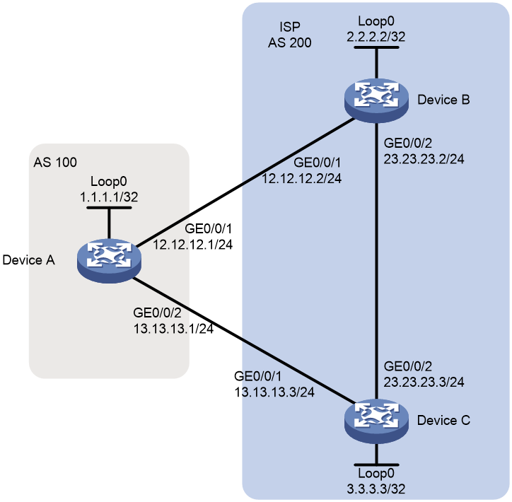
As shown in Figure 2, all devices run BGP. EBGP runs between Device A and Device B, and between Device A and Device C. IBGP runs between Device B and Device C.
Configure a routing policy to ensure that traffic from AS 100 to AS 200 is preferentially forwarded by Device C. Before you configure the routing policy, the traffic is preferentially forwarded by Device B, because Device B has a smaller router ID than Device C.
Analysis
To ensure that the traffic is preferentially forwarded by Device C, configure a routing policy on Device B to change the MED value for the route to Device A. Make sure the MED value is not the default MED value 0.
Software versions used
This configuration example was created and verified on R9141P16 of the MSR2630E-X1 device.
Procedures
Configuring basic BGP
# Configure an IP address for GigabitEthernet 1/0/1 on Device A.
<DeviceA> system-view
[DeviceA] interface gigabitethernet 1/0/1
[DeviceA-GigabitEthernet1/0/1] ip address 12.12.12.1 24
[DeviceA-GigabitEthernet1/0/1] quit
# Configure IP addresses for other interfaces as shown in Figure 2. (Details not shown.)
# On Device A, enable the default BGP instance, set the AS number to 100, and specify 12.12.12.2 and 13.13.13.3 as BGP peers.
[DeviceA] bgp 100
[DeviceA-bgp] router-id 1.1.1.1
[DeviceA-bgp] peer 12.12.12.2 as-number 200
[DeviceA-bgp] peer 13.13.13.3 as-number 200
[DeviceA-bgp] address-family ipv4 unicast
[DeviceA-bgp-ipv4] peer 12.12.12.2 enable
[DeviceA-bgp-ipv4] peer 13.13.13.3 enable
[DeviceA-bgp-ipv4] quit
[DeviceA-bgp] quit
# On Device B, enable the default BGP instance, set the AS number to 200, and specify 12.12.12.1 and 3.3.3.3 as BGP peers.
[DeviceB] bgp 200
[DeviceB-bgp] router-id 2.2.2.2
[DeviceB-bgp] peer 12.12.12.1 as-number 100
[DeviceB-bgp] peer 3.3.3.3 as-number 200
[DeviceB-bgp] peer 3.3.3.3 connect-interface LoopBack0
[DeviceB-bgp] address-family ipv4 unicast
[DeviceB-bgp-ipv4] peer 12.12.12.1 enable
[DeviceB-bgp-ipv4] peer 3.3.3.3 enable
[DeviceB-bgp-ipv4] network 23.23.23.0 24
[DeviceB-bgp-ipv4] quit
[DeviceB-bgp] quit
# Configure a static route to 3.3.3.3/32 on Device B.
[DeviceB] ip route-static 3.3.3.3 32 23.23.23.3
# On Device C, enable the default BGP instance, set the AS number to 200, and specify 13.13.13.1 and 2.2.2.2 as BGP peers.
[DeviceC] bgp 200
[DeviceC-bgp] router-id 3.3.3.3
[DeviceC-bgp] peer 13.13.13.1 as-number 100
[DeviceC-bgp] peer 2.2.2.2 as-number 200
[DeviceC-bgp] peer 2.2.2.2 connect-interface LoopBack0
[DeviceC-bgp] address-family ipv4 unicast
[DeviceC-bgp-ipv4] peer 13.13.13.1 enable
[DeviceC-bgp-ipv4] peer 2.2.2.2 enable
[DeviceC-bgp-ipv4] network 23.23.23.0 24
[DeviceC-bgp-ipv4] quit
[DeviceC-bgp] quit
# Configure a static route to 2.2.2.2/32 on Device C.
[DeviceC] ip route-static 2.2.2.2 32 23.23.23.2
# Display the BGP routing table on Device A. The output shows that the route with the next hop 12.12.12.2 becomes the optimal route to network 23.23.23.0/24.
[DeviceA] display bgp routing-table ipv4
Total number of routes: 2
BGP local router ID is 1.1.1.1
Status codes: * - valid, > - best, d - dampened, h - history,
s - suppressed, S - stale, i - internal, e - external
Origin: i - IGP, e - EGP, ? – incomplete
Network NextHop MED LocPrf PrefVal Path/Ogn
* >e 23.23.23.0/24 12.12.12.2 0 0 200i
* e 13.13.13.3 0 0 200i
Configuring a routing policy
# Create routing policy 10 on Device B and set the cost to 100.
[DeviceB] route-policy 10 permit node 10
[DeviceB-route-policy-10-10] apply cost 100
[DeviceB-route-policy-10-10] quit
# Apply routing policy 10 to routes to peer 12.12.12.1.
[DeviceB] bgp 200
[DeviceB-bgp] address-family ipv4 unicast
[DeviceB-bgp-ipv4] peer 12.12.12.1 route-policy 10 export
[DeviceB-bgp-ipv4] quit
[DeviceB-bgp] quit
Verifying the configuration
# Display the BGP routing table on Device A. The output shows that the MED value for the route with next hop 12.12.12.2 changes to 100, and the route with next hop 13.13.13.3 becomes the optimal route.
[DeviceA] display bgp routing-table ipv4
Total number of routes: 2
BGP local router ID is 1.1.1.1
Status codes: * - valid, > - best, d - dampened, h - history,
s - suppressed, S - stale, i - internal, e - external
Origin: i - IGP, e - EGP, ? – incomplete
Network NextHop MED LocPrf PrefVal Path/Ogn
* >e 23.23.23.0/24 13.13.13.3 0 0 200i
* e 12.12.12.2 100 0 200i
Configuration files
Device A
#
interface LoopBack0
ip address 1.1.1.1 255.255.255.255
#
interface GigabitEthernet1/0/1
port link-mode route
ip address 12.12.12.1 255.255.255.0
#
interface GigabitEthernet1/0/2
port link-mode route
ip address 13.13.13.1 255.255.255.0
#
bgp 100
router-id 1.1.1.1
peer 12.12.12.2 as-number 200
peer 13.13.13.3 as-number 200
#
address-family ipv4 unicast
peer 12.12.12.2 enable
peer 13.13.13.3 enable
#
Device B
#
interface LoopBack0
ip address 2.2.2.2 255.255.255.255
#
interface GigabitEthernet1/0/1
port link-mode route
ip address 12.12.12.2 255.255.255.0
#
interface GigabitEthernet1/0/2
port link-mode route
ip address 23.23.23.2 255.255.255.0
#
bgp 200
router-id 2.2.2.2
peer 3.3.3.3 as-number 200
peer 3.3.3.3 connect-interface LoopBack0
peer 12.12.12.1 as-number 100
#
address-family ipv4 unicast
network 23.23.23.0 255.255.255.0
peer 3.3.3.3 enable
peer 12.12.12.1 enable
peer 12.12.12.1 route-policy 10 export
#
route-policy 10 permit node 10
apply cost 100
#
ip route-static 3.3.3.3 32 23.23.23.3
#
Device C
#
interface LoopBack0
ip address 3.3.3.3 255.255.255.255
#
interface GigabitEthernet1/0/1
port link-mode route
ip address 13.13.13.3 255.255.255.0
#
interface GigabitEthernet1/0/2
port link-mode route
ip address 23.23.23.3 255.255.255.0
#
bgp 200
router-id 3.3.3.3
peer 2.2.2.2 as-number 200
peer 2.2.2.2 connect-interface LoopBack0
peer 13.13.13.1 as-number 100
#
address-family ipv4 unicast
network 23.23.23.0 255.255.255.0
peer 2.2.2.2 enable
peer 13.13.13.1 enable
#
ip route-static 2.2.2.2 32 23.23.23.2
#
Related documentation
· Layer 3—IP Routing Configuration Guide in H3C MSR1000[2600][3600] Routers Configuration Guides(V9)
· Layer 3—IP Routing Command Reference in H3C MSR1000[2600][3600] Routers Command References(V9)