- Table of Contents
-
- H3C MSR1000[2600][3600] Routers Configuration Examples All-in-One-R9141-6W100
- 00-Preface
- 01-Local 802.1X Authentication Configuration Examples
- 02-RADIUS-Based 802.1X Authentication Configuration Examples
- 03-AAA Configuration Examples
- 04-ACL Configuration Examples
- 05-MPLS over ADVPN Configuration Examples
- 06-ARP Attack Protection Configuration Examples
- 07-BFD Configuration Examples
- 08-Basic BGP Configuration Examples
- 09-BGP Route Attribute-Based Route Selection Configuration Examples
- 10-EAA Monitor Policy Configuration Examples
- 11-GRE with OSPF Configuration Examples
- 12-HoVPN Configuration Examples
- 13-IGMP Snooping Configuration Examples
- 14-IGMP Configuration Examples
- 15-IPsec Configuration Examples
- 16-IPsec Digital Certificate Authentication Configuration Examples
- 17-IPv6 IS-IS Configuration Examples
- 18-IPv6 over IPv4 GRE Tunnel Configuration Examples
- 19-IPv6 over IPv4 Manual Tunnel with OSPFv3 Configuration Examples
- 20-IS-IS Configuration Examples
- 21-Combined ISATAP Tunnel and 6to4 Tunnel Configuration Examples
- 22-L2TP over IPsec Configuration Examples
- 23-Multi-Instance L2TP Configuration Examples
- 24-L2TP Multidomain Access Configuration Examples
- 25-MPLS L3VPN Configuration Examples
- 26-MPLS OAM Configuration Examples
- 27-MPLS TE Configuration Examples
- 28-Basic MPLS Configuration Examples
- 29-NAT DNS Mapping Configuration Examples
- 30-NetStream Configuration Examples
- 31-NQA Configuration Examples
- 32-NTP Configuration Examples
- 33-OSPFv3 Configuration Examples
- 34-OSPF Configuration Examples
- 35-OSPF Multi-Process Configuration Examples
- 36-OSPF Multi-Instance Configuration Examples
- 37-Portal Configuration Examples
- 38-PPP Configuration Examples
- 39-RBAC Configuration Examples
- 40-RMON Configuration Examples
- 41-IPv4 NetStream Sampling Configuration Examples
- 42-SNMP Configuration Examples
- 43-SRv6 Configuration Examples
- 44-SSH Configuration Examples
- 45-Tcl Commands Configuration Examples
- 46-VLAN Configuration Examples
- 47-VRRP Configuration Examples
- 48-VXLAN over IPsec Configuration Examples
- 49-WLAN AC Configuration Examples
- 50-Small and Medium-Sized Store Configuration Examples
- 51-Cloudnet VPN Configuration Examples
- 52-Ethernet Link Aggregation Configuration Examples
- 53-Ethernet OAM Configuration Examples
- 54-Outbound Bidirectional NAT Configuration Examples
- 55-NAT Hairpin in C-S Mode Configuration Examples
- 56-Load Sharing NAT Server Configuration Examples
- 57-BIDIR-PIM Configuration Examples
- 58-Control Plane-Based QoS Policy Configuration Examples
- 59-Scheduling a Task Configuration Examples
- 60-Client-Initiated L2TP Tunnel Configuration Examples
- 61-LAC-Auto-Initiated L2TP Tunnel Configuration Examples
- 62-Authorized ARP Configuration Examples
- 63-GTS Configuration Examples
- 64-Traffic Policing Configuration Examples
- 65-Traffic Accounting Configuration Examples
- 66-Mobile Communication Modem Management Configuration Examples
- 67-Port Isolation Configuration Examples
- 68-PBR Configuration Examples
- 69-TFTP Client Software Upgrade Configuration Examples
- 70-FTP Client Software Upgrade Configuration Examples
- 71-FTP Server Software Upgrade Configuration Examples
- 72-Routing Policy Configuration Examples
- 73-Software Upgrade from the BootWare Menu Configuration Examples
- 74-Mirroring Configuration Examples
- Related Documents
-
| Title | Size | Download |
|---|---|---|
| 25-MPLS L3VPN Configuration Examples | 214.85 KB |
|
|
|
H3C Routers |
|
MPLS L3VPN Configuration Examples |
|
|
|
|
Copyright © 2024 New H3C Technologies Co., Ltd. All rights reserved.
No part of this manual may be reproduced or transmitted in any form or by any means without prior written consent of New H3C Technologies Co., Ltd.
Except for the trademarks of New H3C Technologies Co., Ltd., any trademarks that may be mentioned in this document are the property of their respective owners.
The information in this document is subject to change without notice.
Introduction
The following information provides MPLS L3VPN configuration examples.
Prerequisites
The following information applies to Comware 9-based routers. Procedures and information in the examples might be slightly different depending on the software or hardware version of the routers.
The configuration examples were created and verified in a lab environment, and all the devices were started with the factory default configuration. When you are working on a live network, make sure you understand the potential impact of every command on your network.
The following information is provided based on the assumption that you have basic knowledge of MPLS L3VPN.
Example: Configuring MPLS L3VPN
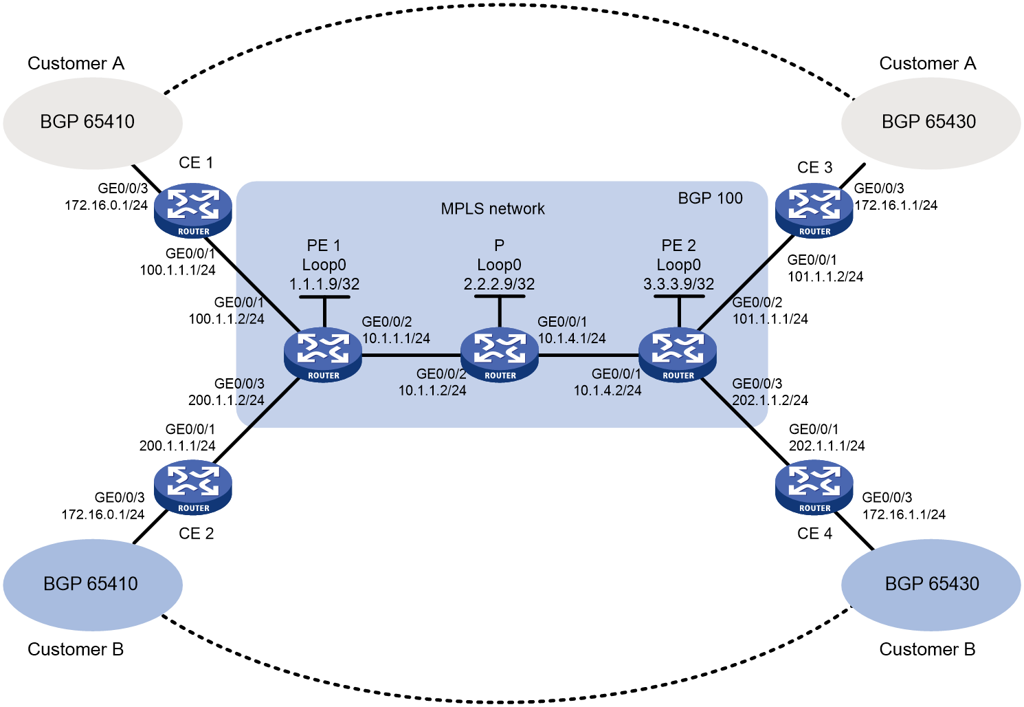
Network configuration
As shown in Figure 1, customer A and customer B each have two dispersed branches. Configure MPLS L3VPN for the customers, so that branches of the same customer can exchange routes and transfer user data with each other while branches of different customers cannot.
Analysis
· To transfer packets on the MPLS network, configure an IGP routing protocol on the MPLS backbone, and use LDP to distribute public network (outer) labels to VPN packets.
· To differentiate routes of different customers, create two VPN instances on each PE, one for customer A and the other for customer B. Configure an RD and RTs for each VPN instance and then redistribute the VPN routes into BGP for the corresponding customer.
· To transport VPN routes and allocate VPN (inner) labels, establish an MP-IBGP peer relationship between the PEs.
Software versions used
This configuration example was created and verified on R9141P16 of the MSR2630E-X1 device.
Restrictions and guidelines
When an interface is bound to a VPN instance, the settings (including IP address) on the interface will be cleared. Therefore, bind an interface to a VPN instance before you configure other settings on the interface.
Procedures
Configuring an IGP protocol (OSPF in this example) on the MPLS backbone to implement IP connectivity between PEs and Ps
Table 1 Configure PE 1:
# Configure IP addresses for the loopback interface and the backbone network interface.
<PE1>system-view
[PE1] interface loopback 0
[PE1-LoopBack0] ip address 1.1.1.9 32
[PE1-LoopBack0] quit
[PE1] interface gigabitethernet 0/0/2
[PE1-GigabitEthernet0/0/2] ip address 10.1.1.1 24
[PE1-GigabitEthernet0/0/2] quit
# Enable OSPF on the interfaces attached to the backbone network.
[PE1]ospf 1
[PE1-ospf-1] area 0
[PE1-ospf-1-area-0.0.0.0] network 10.1.1.0 0.0.0.255
[PE1-ospf-1-area-0.0.0.0] network 1.1.1.9 0.0.0.0
[PE1-ospf-1-area-0.0.0.0] quit
[PE1-ospf-1] quit
Table 2 Configure P:
# Configure IP addresses for the loopback interface and the backbone network interfaces.
<P> system-view
[P] interface loopback 0
[P-LoopBack0] ip address 2.2.2.9 32
[P-LoopBack0] quit
[P] interface gigabitethernet 0/0/2
[P-GigabitEthernet0/0/2] ip address 10.1.1.2 24
[P-GigabitEthernet0/0/2] quit
[P] interface gigabitethernet 0/0/1
[P-GigabitEthernet0/0/1] ip address 10.1.4.1 24
[P-GigabitEthernet0/0/1] quit
# Enable OSPF on the interfaces attached to the backbone network.
[P] ospf 1
[P-ospf-1] area 0
[P-ospf-1-area-0.0.0.0] network 10.1.1.0 0.0.0.255
[P-ospf-1-area-0.0.0.0] network 10.1.4.0 0.0.0.255
[P-ospf-1-area-0.0.0.0] network 2.2.2.9 0.0.0.0
[P-ospf-1-area-0.0.0.0] quit
[P-ospf-1] quit
Table 3 Configure PE 2:
# Configure IP addresses for the loopback interface and the backbone network interface.
<PE2> system-view
[PE2] interface loopback 0
[PE2-LoopBack0] ip address 3.3.3.9 32
[PE2-LoopBack0] quit
[PE2] interface gigabitethernet 0/0/1
[PE2-GigabitEthernet0/0/1] ip address 10.1.4.2 24
[PE2-GigabitEthernet0/0/1] quit
# Enable OSPF on the interfaces attached to the backbone network side.
[PE2] ospf 1
[PE2-ospf-1] area 0
[PE2-ospf-1-area-0.0.0.0] network 10.1.4.0 0.0.0.255
[PE2-ospf-1-area-0.0.0.0] network 3.3.3.9 0.0.0.0
[PE2-ospf-1-area-0.0.0.0] quit
[PE2-ospf-1] quit
After the configuration is completed, PE1, P, and PE2 can establish OSPF neighbor relationship. Execute the display ospf peer command to verify that the neighbors are in full state. Execute the display ip routing-table command to verify that the PEs have learned the routes to the loopback interfaces of each other.
Use PE1 as an example.
[PE1] display ospf peer verbose
OSPF Process 1 with Router ID 1.1.1.9
Neighbors
Area 0.0.0.0 interface 10.1.1.1(GE0/0/2 )'s neighbors
Router ID: 2.2.2.9 Address: 10.1.1.2 GR State: Normal
State: Full Mode: Nbr is Master Priority: 1
DR: 10.1.1.2 BDR: 10.1.1.1 MTU: 0
Options is 0x02 (-|-|-|-|-|-|E|-)
Dead timer due in 38 sec
Neighbor is up for 17:30:25
Authentication Sequence: [ 0 ]
Neighbor state change count: 6
BFD status: Disabled
[PE1] display ip routing-table protocol ospf
Summary Count : 4
OSPF Routing table Status : <Active>
Summary Count : 2
Destination/Mask Proto Pre Cost NextHop Interface
3.3.3.9/32 O_INTRA 10 2 10.1.1.2 GE0/0/2
10.1.4.0/24 O_INTRA 10 2 10.1.1.2 GE0/0/2
OSPF Routing table Status : <Inactive>
Summary Count : 2
Destination/Mask Proto Pre Cost NextHop Interface
1.1.1.9/32 O_INTRA 10 0 0.0.0.0 Loop0
10.1.1.0/24 O_INTRA 10 1 0.0.0.0 GE0/0/2
Configuring basic MPLS and MPLS LDP on the MPLS backbone to establish LDP LSPs
Table 1 Configure PE 1:
# Configure the MPLS LSR ID and enable LDP globally.
[PE1] mpls lsr-id 1.1.1.9
[PE1] mpls ldp
[PE1-ldp] quit
# Enable MPLS and IPv4 LDP capabilities on the interface.
[PE1] interface gigabitethernet 0/0/2
[PE1-GigabitEthernet0/0/2] mpls enable
[PE1-GigabitEthernet0/0/2] mpls ldp enable
[PE1-GigabitEthernet0/0/2] quit
Table 2 Configure P:
# Configure the MPLS LSR ID and enable LDP globally.
[P] mpls lsr-id 2.2.2.9
[P] mpls ldp
[P-ldp] quit
# Enable MPLS and IPv4 LDP capabilities on the interface.
[P] interface gigabitethernet 0/0/2
[P-GigabitEthernet0/0/2] mpls enable
[P-GigabitEthernet0/0/2] mpls ldp enable
[P-GigabitEthernet0/0/2] quit
[P] interface gigabitethernet 0/0/1
[P-GigabitEthernet0/0/1] mpls enable
[P-GigabitEthernet0/0/1] mpls ldp enable
[P-GigabitEthernet0/0/1] quit
Table 3 Configure PE 2:
# Configure the MPLS LSR ID and enable LDP globally.
[PE2] mpls lsr-id 3.3.3.9
[PE2] mpls ldp
[PE2-ldp] quit
# Enable MPLS and IPv4 LDP capabilities on the interface.
[PE2] interface gigabitethernet 0/0/1
[PE2-GigabitEthernet0/0/1] mpls enable
[PE2-GigabitEthernet0/0/1] mpls ldp enable
[PE2-GigabitEthernet0/0/1] quit
Execute the display mpls ldp peer command to verify that LDP sessions in Operational state have been established between PE 1, P, and PE 2. Execute the display mpls ldp lsp command to verify that the LSPs have been established by LDP.
Use PE1 as an example.
[PE1] display mpls ldp peer
Total number of peers: 1
Peer LDP ID State Role GR MD5 KA Sent/Rcvd
2.2.2.9:0 Operational Passive Off Off 5/5
[PE1] display mpls ldp lsp
Status Flags: * - stale, L - liberal, B - backup
FECs: 4 Ingress: 1 Transit: 1 Egress: 3
FEC In/Out Label Nexthop OutInterface
1.1.1.9/32 3/-
-/1151(L)
2.2.2.9/32 -/3 10.1.1.2 GE0/0/2
1151/3 10.1.1.2 GE0/0/2
3.3.3.9/32 -/1150 10.1.1.2 GE0/0/2
1150/1150 10.1.1.2 GE0/0/2
Configuring VPN instances on PEs to allow CE access
Table 1 Configure PE 1:
# On PE 1, create a VPN instance named customerA.
[PE1] ip vpn-instance customerA
# Configure the RD as 100:1 for the VPN instance. The RD is used for generating VPNv4 routes and distinguishing routes of different users on the same network segment.
[PE1-vpn-instance-customerA] route-distinguisher 100:1
# Configure import target 111:1 and export target 222:1 for the VPN instance.
[PE1-vpn-instance-customerA] vpn-target 111:1 import-extcommunity
[PE1-vpn-instance-customerA] vpn-target 222:1 export-extcommunity
[PE1-vpn-instance-customerA] quit
# Create VPN instance customerB in the same way. Configure RD 200:1, import target 333:1, and export target 444:1 for the VPN instance.
[PE1] ip vpn-instance customerB
[PE1-vpn-instance-customerB] route-distinguisher 200:1
[PE1-vpn-instance-customerB] vpn-target 333:1 import-extcommunity
[PE1-vpn-instance-customerB] vpn-target 444:1 export-extcommunity
[PE1-vpn-instance-customerB] quit
# Bind interface GigabitEthernet 0/0/1 to VPN instance customerA.
[PE1] interface gigabitethernet 0/0/1
[PE1-GigabitEthernet0/0/1] ip binding vpn-instance customerA
[PE1-GigabitEthernet0/0/1] ip address 100.1.1.2 24
[PE1-GigabitEthernet0/0/1] quit
# Bind interface GigabitEthernet 0/0/3 to VPN instance customerB.
[PE1] interface gigabitethernet 0/0/3
[PE1-GigabitEthernet0/0/3] ip binding vpn-instance customerB
[PE1-GigabitEthernet0/0/3] ip address 200.1.1.2 24
[PE1-GigabitEthernet0/0/3] quit
Table 2 Configure PE 2:
# On PE 2, create a VPN instance named customerA.
[PE2] ip vpn-instance customerA
# Configure an RD for the VPN instance. For ease of identification, as a best practice, set the same RD as that on PE 1.
[PE2-vpn-instance-customerA] route-distinguisher 100:1
# Configure the import target and export target for the VPN instance, which must be the same as the export target and import target on PE 1.
[PE2-vpn-instance-customerA] vpn-target 222:1 import-extcommunity
[PE2-vpn-instance-customerA] vpn-target 111:1 export-extcommunity
[PE2-vpn-instance-customerA] quit
# Create VPN instance customerB in the same way. Configure RD 200:1, import target 444:1, and export target 333:1 for the VPN instance.
[PE2] ip vpn-instance customerB
[PE2-vpn-instance-customerB] route-distinguisher 200:1
[PE2-vpn-instance-customerB] vpn-target 444:1 import-extcommunity
[PE2-vpn-instance-customerB] vpn-target 333:1 export-extcommunity
[PE2-vpn-instance-customerB] quit
# Bind GigabitEthernet 0/0/2 and GigabitEthernet 0/0/3 to VPN instance customerA and VPN instance customerB, respectively.
[PE2] interface gigabitethernet 0/0/2
[PE2-GigabitEthernet0/0/2] ip binding vpn-instance customerA
[PE2-GigabitEthernet0/0/2] ip address 101.1.1.1 24
[PE2-GigabitEthernet0/0/2] quit
[PE2] interface gigabitethernet 0/0/3
[PE2-GigabitEthernet0/0/3] ip binding vpn-instance customerB
[PE2-GigabitEthernet0/0/3] ip address 202.1.1.2 24
[PE2-GigabitEthernet0/0/3] quit
Table 3 Configure the CE:
# Configure IP addresses for interfaces on the CE as shown in Figure 1. (Details not shown.)
# After the configuration is completed, execute the display ip vpn-instance command on the PEs to view the VPN instance configuration. Each PE can ping its attached CE device.
Use PE 1 and CE 1 as an example.
[PE1] display ip vpn-instance
Total VPN-Instances configured : 2
VPN-Instance Name RD Create time
customerA 100:1 2014/03/22 13:20:08
customerB 200:1 2014/03/22 13:20:20
[PE1] ping -vpn-instance customerA 100.1.1.1
Ping 10.1.1.1 (100.1.1.1): 56 data bytes, press CTRL_C to break
56 bytes from 100.1.1.1: icmp_seq=0 ttl=255 time=1.000 ms
56 bytes from 100.1.1.1: icmp_seq=1 ttl=255 time=2.000 ms
56 bytes from 100.1.1.1: icmp_seq=2 ttl=255 time=0.000 ms
56 bytes from 100.1.1.1: icmp_seq=3 ttl=255 time=1.000 ms
56 bytes from 100.1.1.1: icmp_seq=4 ttl=255 time=0.000 ms
--- Ping statistics for 10.1.1.1 ---
5 packet(s) transmitted, 5 packet(s) received, 0.0% packet loss
round-trip min/avg/max/std-dev = 0.000/0.800/2.000/0.748 ms
Establishing EBGP peer relationships between PEs and CEs, and redistributing VPN routes into BGP
Table 1 Configure PE 1:
# Create BGP process 100 on PE 1.
[PE1] bgp 100
# Specify CE 1 as the peer. Redistribute the direct routes in the routing table of PE 1 into the routing table of the BGP-VPN instance.
[PE1-bgp] ip vpn-instance customerA
[PE1-bgp-customerA] peer 100.1.1.1 as-number 65410
[PE1-bgp-customerA] address-family ipv4 unicast
[PE1-bgp-ipv4-customerA] peer 100.1.1.1 enable
[PE1-bgp-ipv4-customerA] import-route direct
[PE1-bgp-ipv4-customerA] quit
[PE1-bgp-customerA] quit
# Specify CE 2 as the peer. Redistribute the direct routes in the routing table of PE 1 into the routing table of the BGP-VPN instance.
[PE1-bgp] ip vpn-instance customerB
[PE1-bgp-customerB] peer 200.1.1.1 as-number 65410
[PE1-bgp-customerB] address-family ipv4 unicast
[PE1-bgp-ipv4-customerB] peer 200.1.1.1 enable
[PE1-bgp-ipv4-customerB] import-route direct
[PE1-bgp-ipv4-customerB] quit
[PE1-bgp-customerB] quit
[PE1-bgp] quit
Table 2 Configure PE 2:
# Create BGP process 100 on PE 2.
[PE2] bgp 100
# Specify CE 3 as the peer. Redistribute the direct routes in the routing table of PE 2 into the routing table of the BGP-VPN instance.
[PE2-bgp] ip vpn-instance customerA
[PE2-bgp-customerA] peer 101.1.1.2 as-number 65430
[PE2-bgp-customerA] address-family ipv4 unicast
[PE2-bgp-ipv4-customerA] peer 101.1.1.2 enable
[PE2-bgp-ipv4-customerA] import-route direct
[PE2-bgp-ipv4-customerA] quit
[PE2-bgp-customerA] quit
# Specify CE 4 as the peer. Redistribute the direct routes in the routing table of PE 2 into the routing table of the BGP-VPN instance.
[PE2-bgp] ip vpn-instance customerB
[PE2-bgp-customerB] peer 202.1.1.1 as-number 65430
[PE2-bgp-customerB] address-family ipv4 unicast
[PE2-bgp-ipv4-customerB] peer 202.1.1.1 enable
[PE2-bgp-ipv4-customerB] import-route direct
[PE2-bgp-ipv4-customerB] quit
[PE2-bgp-customerB] quit
[PE2-bgp] quit
Table 3 Configure CE 1:
# Create BGP process 65410 on CE 1. Specify PE 1 as the peer with AS number 100.
<CE1>system-view
[CE1] bgp 65410
[CE1-bgp] peer 100.1.1.2 as-number 100
# Enable CE 1 to exchange IPv4 unicast routing information with peer 100.1.1.2.
[CE1-bgp] address-family ipv4 unicast
[CE1-bgp-ipv4] peer 100.1.1.2 enable
# Redistribute the direct route connected to the host on CE 1 into EBGP.
[CE1-bgp-ipv4] import-route direct
[CE1-bgp-ipv4] quit
[CE1-bgp] quit
Table 4 Configure CE 2:
# Create BGP process 65410 on CE 2. Specify PE 1 as the peer with AS number 100.
<CE2> system-view
[CE2] bgp 65410
[CE2-bgp] peer 200.1.1.2 as-number 100
# Enable CE 2 to exchange IPv4 unicast routing information with peer 200.1.1.2.
[CE2-bgp] address-family ipv4 unicast
[CE2-bgp-ipv4] peer 200.1.1.2 enable
# Redistribute the direct route connected to the host on CE 2 into EBGP.
[CE2-bgp-ipv4] import-route direct
[CE2-bgp-ipv4] quit
[CE2-bgp] quit
Table 5 Configure CE 3:
# Create BGP process 65430 on CE 3. Specify PE 2 as the peer with AS number 100.
<CE3>system-view
[CE3] bgp 65430
[CE3-bgp] peer 101.1.1.1 as-number 100
# Enable CE 3 to exchange IPv4 unicast routing information with peer 101.1.1.1.
[CE3-bgp] address-family ipv4 unicast
[CE3-bgp-ipv4] peer 101.1.1.1 enable
# Redistribute the direct route connected to the host on CE 3 into EBGP.
[CE3-bgp-ipv4] import-route direct
[CE3-bgp-ipv4] quit
[CE3-bgp] quit
Table 6 Configure CE 4:
# Create BGP process 65430 on CE 4. Specify PE 2 as the peer with AS number 100.
<CE4>system-view
[CE4] bgp 65430
[CE4-bgp] peer 202.1.1.2 as-number 100
# Enable CE 4 to exchange IPv4 unicast routing information with peer 202.1.1.2.
[CE4-bgp] address-family ipv4 unicast
[CE4-bgp-ipv4] peer 202.1.1.2 enable
# Redistribute the direct route connected to the host on CE 4 into EBGP.
[CE4-bgp-ipv4] import-route direct
[CE4-bgp-ipv4] quit
[CE4-bgp] quit
After the configuration is completed, execute the display bgp peer ipv4 vpn-instance command to verify that the BGP peer relationships have been established between PEs and CEs and are in Established state.
Use PE 1 and CE 1 as an example:
[PE1] display bgp peer ipv4 vpn-instance customerA
BGP local router ID: 1.1.1.9
Local AS number: 100
Total number of peers: 1 Peers in established state: 1
Peer AS MsgRcvd MsgSent OutQ PrefRcv Up/Down State
100.1.1.1 65410 4 4 0 2 13:35:25 Established
Establishing an MP-IBGP peer relationship between PEs
Table 1 Configure PE 1:
# On PE 1, specify PE 2 as the BGP peer, and specify loopback 0 as the source interface for TCP connections to the peer.
[PE1] bgp 100
[PE1-bgp] peer 3.3.3.9 as-number 100
[PE1-bgp] peer 3.3.3.9 connect-interface loopback 0
# Enter BGP VPNv4 address family view, and specify PE 2 as the peer.
[PE1-bgp] address-family vpnv4
[PE1-bgp-vpnv4] peer 3.3.3.9 enable
[PE1-bgp-vpnv4] quit
[PE1-bgp] quit
Table 2 Configure PE 2:
# On PE 2, specify PE 1 as the BGP peer, and specify Loopback 0 as the source interface for TCP connections to the peer.
[PE2] bgp 100
[PE2-bgp] peer 1.1.1.9 as-number 100
[PE2-bgp] peer 1.1.1.9 connect-interface loopback 0
# Enter BGP VPNv4 address family view, and specify PE 1 as the peer.
[PE2-bgp] address-family vpnv4
[PE2-bgp-vpnv4] peer 1.1.1.9 enable
[PE2-bgp-vpnv4] quit
[PE2-bgp] quit
After the configuration is completed, execute the display bgp peer vpnv4 command to verify that the BGP peer relationships have been established between PEs and are in Established state.
[PE1] display bgp peer vpnv4
BGP local router ID: 1.1.1.9
Local AS number: 100
Total number of peers: 1 Peers in established state: 1
Peer AS MsgRcvd MsgSent OutQ PrefRcv Up/Down State
3.3.3.9 100 8 8 0 0 00:00:08 Established
Verifying the configuration
# Execute the display ip routing-table vpn-instance command on a PE to view the route destined to the peer CE.
Use VPN instance customerA on PE 1 as an example:
[PE1] display ip routing-table vpn-instance customerA
Destinations : 13 Routes : 13
Destination/Mask Proto Pre Cost NextHop Interface
0.0.0.0/32 Direct 0 0 127.0.0.1 InLoop0
100.1.1.0/24 Direct 0 0 100.1.1.2 GE0/0/1
100.1.1.0/32 Direct 0 0 100.1.1.2 GE0/0/1
100.1.1.2/32 Direct 0 0 127.0.0.1 InLoop0
100.1.1.255/32 Direct 0 0 100.1.1.2 GE0/0/1
101.1.1.0/24 BGP 255 0 3.3.3.9 GE0/0/2
127.0.0.0/8 Direct 0 0 127.0.0.1 InLoop0
127.0.0.0/32 Direct 0 0 127.0.0.1 InLoop0
127.0.0.1/32 Direct 0 0 127.0.0.1 InLoop0
127.255.255.255/32 Direct 0 0 127.0.0.1 InLoop0
224.0.0.0/4 Direct 0 0 0.0.0.0 NULL0
224.0.0.0/24 Direct 0 0 0.0.0.0 NULL0
255.255.255.255/32 Direct 0 0 127.0.0.1 InLoop0
CEs in the same VPN can ping each other. CEs in different VPNs cannot ping each other.
For example, CE 1 can ping CE 3 (101.1.1.2), but it cannot ping CE 4 (202.1.1.1).
Configuration files
· PE 1:
#
ip vpn-instance customerA
route-distinguisher 100:1
vpn-target 111:1 import-extcommunity
vpn-target 222:1 export-extcommunity
#
ip vpn-instance customerB
route-distinguisher 200:1
vpn-target 333:1 import-extcommunity
vpn-target 444:1 export-extcommunity
#
ospf 1
area 0.0.0.0
network 1.1.1.9 0.0.0.0
network 10.1.1.0 0.0.0.255
#
mpls lsr-id 1.1.1.9
#
mpls ldp
#
interface LoopBack0
ip address 1.1.1.9 255.255.255.255
#
interface GigabitEthernet0/0/1
port link-mode route
ip binding vpn-instance customerA
ip address 100.1.1.2 255.255.255.0
#
interface GigabitEthernet0/0/2
port link-mode route
ip address 10.1.1.1 255.255.255.0
mpls enable
mpls ldp enable
#
interface GigabitEthernet0/0/3
port link-mode route
ip binding vpn-instance customerB
ip address 200.1.1.2 255.255.255.0
#
bgp 100
peer 3.3.3.9 as-number 100
peer 3.3.3.9 connect-interface LoopBack0
#
address-family vpnv4
peer 3.3.3.9 enable
#
ip vpn-instance customerA
peer 100.1.1.1 as-number 65410
#
address-family ipv4 unicast
import-route direct
peer 100.1.1.1 enable
#
ip vpn-instance customerB
peer 200.1.1.1 as-number 65410
#
address-family ipv4 unicast
import-route direct
peer 200.1.1.1 enable
#
· P:
#
ospf 1
area 0.0.0.0
network 2.2.2.9 0.0.0.0
network 10.1.1.0 0.0.0.255
network 10.1.4.0 0.0.0.255
#
mpls lsr-id 2.2.2.9
#
mpls ldp
#
interface LoopBack0
ip address 2.2.2.9 255.255.255.255
#
interface GigabitEthernet0/0/1
port link-mode route
ip address 10.1.4.1 255.255.255.0
mpls enable
mpls ldp enable
#
interface GigabitEthernet0/0/2
port link-mode route
ip address 10.1.1.2 255.255.255.0
mpls enable
mpls ldp enable
#
· PE 2:
#
ip vpn-instance customerA
route-distinguisher 100:1
vpn-target 111:1 export-extcommunity
vpn-target 222:1 import-extcommunity
#
ip vpn-instance customerB
route-distinguisher 200:1
vpn-target 333:1 export-extcommunity
vpn-target 444:1 import-extcommunity
#
ospf 1
area 0.0.0.0
network 10.1.4.0 0.0.0.255
network 3.3.3.9 0.0.0.0
#
mpls lsr-id 3.3.3.9
#
mpls ldp
#
interface LoopBack0
ip address 3.3.3.9 255.255.255.255
#
interface GigabitEthernet0/0/1
port link-mode route
ip address 10.1.4.2 255.255.255.0
mpls enable
mpls ldp enable
#
interface GigabitEthernet0/0/2
port link-mode route
ip binding vpn-instance customerA
ip address 101.1.1.1 255.255.255.0
#
interface GigabitEthernet0/0/3
port link-mode route
ip binding vpn-instance customerB
ip address 202.1.1.2 255.255.255.0
#
bgp 100
peer 1.1.1.9 as-number 100
peer 1.1.1.9 connect-interface LoopBack0
#
address-family vpnv4
peer 1.1.1.9 enable
#
ip vpn-instance customerA
peer 101.1.1.2 as-number 65430
#
address-family ipv4 unicast
import-route direct
peer 101.1.1.2 enable
#
ip vpn-instance customerB
peer 202.1.1.1 as-number 65430
#
address-family ipv4 unicast
import-route direct
peer 202.1.1.1 enable
#
· CE 1:
#
interface GigabitEthernet0/0/1
port link-mode route
ip address 100.1.1.1 255.255.255.0
#
bgp 65410
peer 100.1.1.2 as-number 100
#
address-family ipv4 unicast
import-route direct
peer 100.1.1.2 enable
#
· CE 2:
#
interface GigabitEthernet0/0/1
port link-mode route
ip address 200.1.1.1 255.255.255.0
#
bgp 65410
peer 200.1.1.2 as-number 100
#
address-family ipv4 unicast
import-route direct
peer 200.1.1.2 enable
#
· CE 3:
#
interface GigabitEthernet0/0/1
port link-mode route
ip address 101.1.1.2 255.255.255.0
#
bgp 65430
peer 101.1.1.1 as-number 100
#
address-family ipv4 unicast
import-route direct
peer 101.1.1.1 enable
#
· CE 4:
#
interface GigabitEthernet0/0/1
port link-mode route
ip address 202.1.1.1 255.255.255.0
#
bgp 65430
peer 202.1.1.2 as-number 100
#
address-family ipv4 unicast
import-route direct
peer 202.1.1.2 enable
#
Related documentation
· MPLS Configuration Guide in H3C MSR1000[2600][3600] Routers Configuration Guides (V9)
· MPLS Command Reference in H3C MSR1000[2600][3600] Routers Command References (V9)
· Layer 3—IP Routing Configuration Guide in H3C MSR1000[2600][3600] Routers Configuration Guides (V9)
· Layer 3—IP Routing Command Reference in H3C MSR1000[2600][3600] Routers Command References (V9)