- Table of Contents
-
- H3C MSR1000[2600][3600] Routers Configuration Examples All-in-One-R9141-6W100
- 00-Preface
- 01-Local 802.1X Authentication Configuration Examples
- 02-RADIUS-Based 802.1X Authentication Configuration Examples
- 03-AAA Configuration Examples
- 04-ACL Configuration Examples
- 05-MPLS over ADVPN Configuration Examples
- 06-ARP Attack Protection Configuration Examples
- 07-BFD Configuration Examples
- 08-Basic BGP Configuration Examples
- 09-BGP Route Attribute-Based Route Selection Configuration Examples
- 10-EAA Monitor Policy Configuration Examples
- 11-GRE with OSPF Configuration Examples
- 12-HoVPN Configuration Examples
- 13-IGMP Snooping Configuration Examples
- 14-IGMP Configuration Examples
- 15-IPsec Configuration Examples
- 16-IPsec Digital Certificate Authentication Configuration Examples
- 17-IPv6 IS-IS Configuration Examples
- 18-IPv6 over IPv4 GRE Tunnel Configuration Examples
- 19-IPv6 over IPv4 Manual Tunnel with OSPFv3 Configuration Examples
- 20-IS-IS Configuration Examples
- 21-Combined ISATAP Tunnel and 6to4 Tunnel Configuration Examples
- 22-L2TP over IPsec Configuration Examples
- 23-Multi-Instance L2TP Configuration Examples
- 24-L2TP Multidomain Access Configuration Examples
- 25-MPLS L3VPN Configuration Examples
- 26-MPLS OAM Configuration Examples
- 27-MPLS TE Configuration Examples
- 28-Basic MPLS Configuration Examples
- 29-NAT DNS Mapping Configuration Examples
- 30-NetStream Configuration Examples
- 31-NQA Configuration Examples
- 32-NTP Configuration Examples
- 33-OSPFv3 Configuration Examples
- 34-OSPF Configuration Examples
- 35-OSPF Multi-Process Configuration Examples
- 36-OSPF Multi-Instance Configuration Examples
- 37-Portal Configuration Examples
- 38-PPP Configuration Examples
- 39-RBAC Configuration Examples
- 40-RMON Configuration Examples
- 41-IPv4 NetStream Sampling Configuration Examples
- 42-SNMP Configuration Examples
- 43-SRv6 Configuration Examples
- 44-SSH Configuration Examples
- 45-Tcl Commands Configuration Examples
- 46-VLAN Configuration Examples
- 47-VRRP Configuration Examples
- 48-VXLAN over IPsec Configuration Examples
- 49-WLAN AC Configuration Examples
- 50-Small and Medium-Sized Store Configuration Examples
- 51-Cloudnet VPN Configuration Examples
- 52-Ethernet Link Aggregation Configuration Examples
- 53-Ethernet OAM Configuration Examples
- 54-Outbound Bidirectional NAT Configuration Examples
- 55-NAT Hairpin in C-S Mode Configuration Examples
- 56-Load Sharing NAT Server Configuration Examples
- 57-BIDIR-PIM Configuration Examples
- 58-Control Plane-Based QoS Policy Configuration Examples
- 59-Scheduling a Task Configuration Examples
- 60-Client-Initiated L2TP Tunnel Configuration Examples
- 61-LAC-Auto-Initiated L2TP Tunnel Configuration Examples
- 62-Authorized ARP Configuration Examples
- 63-GTS Configuration Examples
- 64-Traffic Policing Configuration Examples
- 65-Traffic Accounting Configuration Examples
- 66-Mobile Communication Modem Management Configuration Examples
- 67-Port Isolation Configuration Examples
- 68-PBR Configuration Examples
- 69-TFTP Client Software Upgrade Configuration Examples
- 70-FTP Client Software Upgrade Configuration Examples
- 71-FTP Server Software Upgrade Configuration Examples
- 72-Routing Policy Configuration Examples
- 73-Software Upgrade from the BootWare Menu Configuration Examples
- 74-Mirroring Configuration Examples
- Related Documents
-
| Title | Size | Download |
|---|---|---|
| 13-IGMP Snooping Configuration Examples | 146.52 KB |
|
|
|
H3C Routers |
|
IGMP Snooping Configuration Examples |
|
|
|
|
Copyright © 2024 New H3C Technologies Co., Ltd. All rights reserved.
No part of this manual may be reproduced or transmitted in any form or by any means without prior written consent of New H3C Technologies Co., Ltd.
Except for the trademarks of New H3C Technologies Co., Ltd., any trademarks that may be mentioned in this document are the property of their respective owners.
The information in this document is subject to change without notice.
Introduction
The following information provides IGMP snooping group policy and static port configuration examples.
IGMP snooping runs on a Layer 2 device as a multicast constraining mechanism to improve multicast forwarding efficiency. It creates Layer 2 multicast forwarding entries from IGMP messages that are exchanged between the hosts and the Layer 3 device.
Prerequisites
The following information applies to Comware 9-based routers. Procedures and information in the examples might be slightly different depending on the software or hardware version of the routers.
The configuration examples were created and verified in a lab environment, and all the devices were started with the factory default configuration. When you are working on a live network, make sure you understand the potential impact of every command on your network.
The following information is provided based on the assumption that you have basic knowledge of IGMP snooping.
Example: Configuring multicast group policies
Network configuration
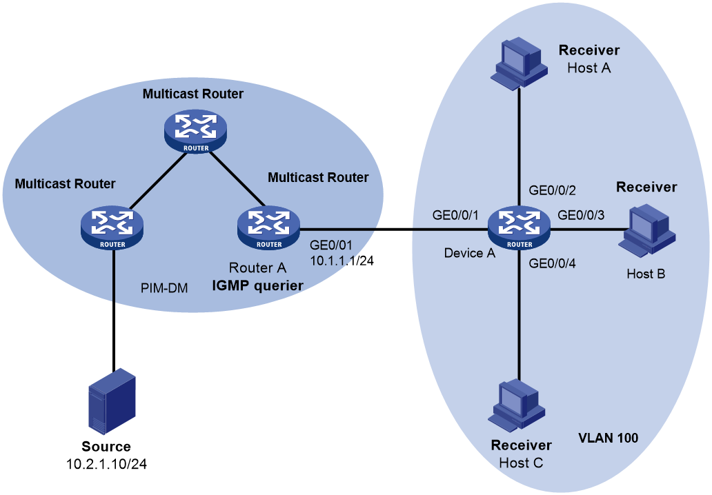
As shown in Figure 1, VLAN 100 is connected to the PIM-DM domain through Device A. Router A runs IGMP and acts as the IGMP querier. Device A runs IGMP snooping. Configure IGMP snooping and a multicast group policy to meet the following requirements:
· Host A receives only the multicast data addressed to multicast group 224.1.1.1. All other hosts (for example, Host B and Host C) receive only the multicast data addressed to multicast group 225.1.1.1.
· Device A drops unknown multicast data instead of broadcasting it in VLAN 100.
Analysis
· By default, IGMP snooping version 2 can process IGMPv1 and IGMPv2 messages, but not IGMPv3 messages, which will be flooded in the VLAN. To avoid this situation, configure IGMP snooping version 3 in VLAN 100.
· By default, all multicast data not permitted by a multicast group policy is broadcast in VLAN 100, and receivers in VLAN 100 can receive that multicast data. To avoid this situation, enable dropping unknown multicast data packets.
· To control the multicast groups that hosts can join, create a basic ACL and configure a rule to specify a multicast group range.
Software versions used
This configuration example was created and verified on Release 9141P16 of the MSR2630E-X1 router.
Restrictions and guidelines
· To enable IGMP snooping in a VLAN, first enable IGMP snooping globally.
· You can configure a multicast group policy for a port in interface view or globally for all ports in IGMP snooping view. For a port, the port-specific configuration takes priority over the global configuration.
Procedures
1. Prerequisites:
# Assign an IP address and subnet mask to each interface. (Details not shown.)
# Configure static routing or dynamic routing for interconnection between the routers in the PIM-DM domain. (Details not shown.)
# Enable PIM-DM on each router. PIM-DM enables the router to establish multicast forwarding entries, which can be used to forward multicast data from the multicast source to multicast receivers.
2. Configure Router A:
# Enable IP multicast routing.
<RouterA> system-view
[RouterA] multicast routing
[RouterA-mrib] quit
# Enable IGMP and specify IGMP version 3 on GigabitEthernet 0/0/1.
[RouterA] interface gigabitethernet 0/0/1
[RouterA-GigabitEthernet0/0/1] igmp enable
[RouterA-GigabitEthernet0/0/1] igmp version 3
[RouterA-GigabitEthernet0/0/1] quit
3. Configure Device A:
# Enable IGMP snooping globally.
<DeviceA> system-view
[DeviceA] igmp-snooping
[DeviceA-igmp-snooping] quit
# Create VLAN 100, assign GigabitEthernet 0/0/1 through GigabitEthernet 0/0/4 to the VLAN, enable IGMP snooping and specify IGMP snooping version 3 in the VLAN, and enable dropping unknown multicast data packets.
[DeviceA] vlan 100
[DeviceA-vlan100] port gigabitethernet 0/0/1 to gigabitethernet 0/0/4
[DeviceA-vlan100] igmp-snooping enable
[DeviceA-vlan100] igmp-snooping version 3
[DeviceA-vlan100] igmp-snooping drop-unknown
[DeviceA-vlan100] quit
# Configure a multicast group policy on GigabitEthernet 0/0/2 to specify that Host A in VLAN 100 can join only multicast group 224.1.1.1.
[DeviceA] acl number 2000
[DeviceA-acl-basic-2000] rule permit source 224.1.1.1 0
[DeviceA-acl-basic-2000] quit
[DeviceA] interface gigabitethernet 0/0/2
[DeviceA-GigabitEthernet0/0/2] igmp-snooping group-policy 2000 vlan 100
[DeviceA-GigabitEthernet0/0/2] quit
# Configure a multicast group policy to specify that all other hosts in VLAN 100 can join only multicast group 225.1.1.1.
[DeviceA] acl number 2001
[DeviceA-acl-basic-2001] rule permit source 225.1.1.1 0
[DeviceA-acl-basic-2001] quit
[DeviceA] igmp-snooping
[DeviceA-igmp-snooping] group-policy 2001 vlan 100
[DeviceA-igmp-snooping] quit
Verifying the configuration
Send multicast data from the multicast source to multicast groups 224.1.1.1, 224.2.2.2, and 225.1.1.1.
# Display information about dynamic IGMP snooping group entries in VLAN 100 on Device A.
[DeviceA] display igmp-snooping group vlan 100
Total 2 entries.
VLAN 100: Total 2 entries.
(0.0.0.0, 224.1.1.1)
Host slots (1 in total):
3
Host ports (1 in total):
GE0/0/2
(0.0.0.0, 225.1.1.1)
Host slots (1 in total):
3
Host ports (2 in total):
GE0/0/3
GE0/0/4
The output shows that GigabitEthernet 0/0/2 to which Host A attached joined multicast group 224.1.1.1 but did not join multicast group 224.2.2.2 or 225.1.1.1. GigabitEthernet 0/0/3 and GigabitEthernet 0/0/4 joined multicast group 225.1.1.1 but did not join multicast group 224.1.1.1 or 224.2.2.2.
Configuration files
· Router A:
#
interface GigabitEthernet0/0/1
port link-mode route
ip address 10.1.1.1 255.255.255.0
igmp enable
igmp version 3
#
multicast routing
#
· Device A:
#
igmp-snooping
group-policy 2001 vlan 100
#
vlan 100
igmp-snooping enable
igmp-snooping drop-unknown
igmp-snooping version 3
#
interface GigabitEthernet0/0/1
port link-mode bridge
port access vlan 100
#
interface GigabitEthernet0/0/2
port link-mode bridge
port access vlan 100
igmp-snooping group-policy 2000 vlan 100
#
interface GigabitEthernet0/0/3
port link-mode bridge
port access vlan 100
#
interface GigabitEthernet0/0/4
port link-mode bridge
port access vlan 100
#
acl number 2000
rule 0 permit source 224.1.1.1 0
#
acl number 2001
rule 0 permit source 225.1.1.1 0
#
Example: Configuring static ports
Network configuration
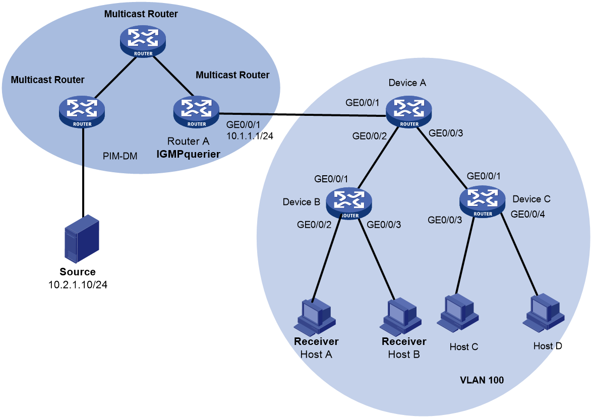
As shown in Figure 2, VLAN 100 is connected to the PIM-DM domain through Device A. Each device in VLAN 100 runs IGMP snooping. Router A runs IGMPv2 and acts as the IGMP querier.
A ring topology is used for enhancing the reliability of multicast traffic transmission. STP is used for avoiding loops. One of the links between Device A and Device B (Device A—Device B or Device A—Device C—Device B) will be blocked.
Configure static ports to meet the following requirements:
· After one link between Device A and Device B switch to the other link and the STP state of the new link becomes stable, multicast data can be immediately sent to receivers over the new link.
· Host A, Host B, and Host C can always receive the multicast data addressed to multicast group 224.1.1.1.
Analysis
· After a link switchover is completed, a minimum of one IGMP query-response cycle must be completed before multicast data flows to the receivers along the new link. In this case, the multicast delivery is interrupted during the process. To avoid this situation, configure GigabitEthernet 0/0/2 and GigabitEthernet 0/0/3 on Device A, GigabitEthernet 0/0/4 on Device B, and GigabitEthernet 0/0/2 on Device C as static router ports. Then, multicast data will be fast directed to static router ports and switched to the new link for transmission.
· For Host A, Host B, and Host C to always receive the multicast data addressed to multicast group 224.1.1.1, configure GigabitEthernet 0/0/2 and GigabitEthernet 0/0/3 on Device B and GigabitEthernet 0/0/3 on Device C as static member ports.
Software versions used
This configuration example was created and verified on Release 9141P16 of the MSR2630E-X1 router.
Restrictions and guidelines
To successfully enable IGMP snooping in a VLAN, first enable IGMP snooping globally.
Procedures
1. Prerequisites:
# Assign an IP address and subnet mask to each interface. (Details not shown.)
# Configure OSPF for interconnection between the routers in the PIM-DM domain. (Details not shown.)
# Enable PIM-DM on each router. PIM-DM enables the router to establish multicast forwarding entries, which can be used to forward multicast data from the source to receivers.
2. Configuring Router A:
# Enable IP multicast routing.
<RouterA> system-view
[RouterA] multicast routing
[RouterA-mrib] quit
# Enable IGMP snooping on GigabitEthernet 0/0/1.
[RouterA] interface gigabitethernet 0/0/1
[RouterA-GigabitEthernet0/0/1] igmp enable
[RouterA-GigabitEthernet0/0/1] quit
3. Configure Device A:
# Enable IGMP snooping globally.
<DeviceA> system-view
[DeviceA] igmp-snooping
[DeviceA-igmp-snooping] quit
# Create VLAN 100, assign GigabitEthernet 0/0/1 through GigabitEthernet 0/0/4 to the VLAN, and enable IGMP snooping in the VLAN.
[DeviceA] vlan 100
[DeviceA-vlan100] port gigabitethernet 0/0/1 to gigabitethernet 0/0/4
[DeviceA-vlan100] igmp-snooping enable
[DeviceA-vlan100] quit
# Configure GigabitEthernet 0/0/2 and GigabitEthernet 0/0/3 as static router ports.
[DeviceA] interface gigabitethernet 0/0/2
[DeviceA-GigabitEthernet0/0/2] igmp-snooping static-router-port vlan 100
[DeviceA-GigabitEthernet0/0/2] quit
[DeviceA] interface gigabitethernet 0/0/3
[DeviceA-GigabitEthernet0/0/3] igmp-snooping static-router-port vlan 100
[DeviceA-GigabitEthernet0/0/3] quit
4. Configure Device B:
# Enable IGMP snooping globally.
<DeviceB> system-view
[DeviceB] igmp-snooping
[DeviceB-igmp-snooping] quit
# Create VLAN 100, assign GigabitEthernet 0/0/1 and GigabitEthernet 0/0/4 to the VLAN, and enable IGMP snooping in the VLAN.
[DeviceB] vlan 100
[DeviceB-vlan100] port gigabitethernet 0/0/1 gigabitethernet 0/0/4
[DeviceB-vlan100] igmp-snooping enable
[DeviceB-vlan100] quit
# Configure GigabitEthernet 0/0/4 as a static router port.
[DeviceB] interface gigabitethernet 0/0/4
[DeviceB-GigabitEthernet0/0/4] igmp-snooping static-router-port vlan 100
[DeviceB-GigabitEthernet0/0/4] quit
# Configure GigabitEthernet 0/0/2 and GigabitEthernet 0/0/3 as static member ports of multicast group 224.1.1.1 in VLAN 100.
[DeviceB] interface gigabitethernet 0/0/2
[DeviceB-GigabitEthernet0/0/2] igmp-snooping static-group 224.1.1.1 vlan 100
[DeviceB-GigabitEthernet0/0/2] quit
[DeviceB] interface gigabitethernet 0/0/3
[DeviceB-GigabitEthernet0/0/3] igmp-snooping static-group 224.1.1.1 vlan 100
[DeviceB-GigabitEthernet0/0/3] quit
5. Configure Device C:
# Enable IGMP snooping globally.
<DeviceC> system-view
[DeviceC] igmp-snooping
[DeviceC-igmp-snooping] quit
# Create VLAN 100, assign GigabitEthernet 0/0/1 through GigabitEthernet 0/0/4 to the VLAN, and enable IGMP snooping in the VLAN.
[DeviceC] vlan 100
[DeviceC-vlan100] port gigabitethernet 0/0/1 to gigabitethernet 0/0/4
[DeviceC-vlan100] igmp-snooping enable
[DeviceC-vlan100] quit
# Configure GigabitEthernet 0/0/2 as a static router port.
[DeviceC] interface gigabitethernet 0/0/2
[DeviceC-GigabitEthernet0/0/2] igmp-snooping static-router-port vlan 100
[DeviceC-GigabitEthernet0/0/2] quit
# Configure GigabitEthernet 0/0/3 as a static member port of multicast group 224.1.1.1 in VLAN 100.
[DeviceC] interface gigabitethernet 0/0/3
[DeviceC-GigabitEthernet0/0/3] igmp-snooping static-group 224.1.1.1 vlan 100
[DeviceC-GigabitEthernet0/0/3] quit
Verifying the configuration
# Display static router port information in VLAN 10 on Device A.
[DeviceA] display igmp-snooping static-router-port vlan 100
VLAN 100:
Router slots (1 in total):
3
Router ports (2 in total):
GE0/0/2
GE0/0/3
The output shows that GigabitEthernet 0/0/2 and GigabitEthernet 0/0/3 on Device A have become static router ports.
# Display static router port information in VLAN 10 on Device B.
[DeviceB] display igmp-snooping static-router-port vlan 100
VLAN 100:
Router slots (1 in total):
3
Router ports (1 in total):
GE0/0/4
The output shows that GigabitEthernet 0/0/4 on Device B has become a static router port.
# Display information about static IGMP snooping group entries in VLAN 100 on Device B.
[DeviceB] display igmp-snooping static-group vlan 100
Total 1 entries.
VLAN 100: Total 1 entries.
(0.0.0.0, 224.1.1.1)
Host slots (1 in total):
3
Host ports (2 in total):
GE0/0/2
GE0/0/3
The output shows that GigabitEthernet 0/0/2 and GigabitEthernet 0/0/3 on Device B have become static member ports of multicast group 224.1.1.1 in VLAN 100.
# Display static router port information in VLAN 10 on Device C.
[DeviceC] display igmp-snooping static-router-port vlan 100
VLAN 100:
Router slots (1 in total):
3
Router ports (1 in total):
GE0/0/2
The output shows that GigabitEthernet 0/0/2 on Device C has become a static router port.
# Display information about static IGMP snooping group entries in VLAN 100 on Device C.
[DeviceC] display igmp-snooping static-group vlan 100
Total 1 entries.
VLAN 100: Total 1 entries.
(0.0.0.0, 224.1.1.1)
Host slots (1 in total):
3
Host ports (1 in total):
GE0/0/3
The output shows that GigabitEthernet 0/0/3 on Device C has become a static member port of multicast group 224.1.1.1 in VLAN 100.
Configuration files
· Router A:
#
interface GigabitEthernet0/0/1
port link-mode route
ip address 10.1.1.1 255.255.255.0
igmp enable
igmp version 2
#
multicast routing
#
· Device A:
#
igmp-snooping
#
vlan 100
igmp-snooping enable
#
interface GigabitEthernet0/0/1
port link-mode bridge
port access vlan 100
#
interface GigabitEthernet0/0/2
port link-mode bridge
port access vlan 100
igmp-snooping static-router-port vlan 100
#
interface GigabitEthernet0/0/3
port link-mode bridge
port access vlan 100
igmp-snooping static-router-port vlan 100
#
· Device B:
#
igmp-snooping
#
vlan 100
igmp-snooping enable
#
interface GigabitEthernet0/0/1
port link-mode bridge
port access vlan 100
#
interface GigabitEthernet0/0/2
port link-mode bridge
port access vlan 100
igmp-snooping static-group 224.1.1.1 vlan 100
#
interface GigabitEthernet0/0/3
port link-mode bridge
port access vlan 100
igmp-snooping static-group 224.1.1.1 vlan 100
#
interface GigabitEthernet0/0/4
port link-mode bridge
port access vlan 100
igmp-snooping static-router-port vlan 100
#
· Device C:
#
igmp-snooping
#
vlan 100
igmp-snooping enable
#
interface GigabitEthernet0/0/1
port link-mode bridge
port access vlan 100
#
interface GigabitEthernet0/0/2
port link-mode bridge
port access vlan 100
igmp-snooping static-router-port vlan 100
#
interface GigabitEthernet0/0/3
port link-mode bridge
port access vlan 100
igmp-snooping static-group 224.1.1.1 vlan 100
#
interface GigabitEthernet0/0/4
port link-mode bridge
port access vlan 100
#
Related documentation
· IP Multicast Configuration Guide in H3C MSR1000[2600][3600] Routers Configuration Guides(V9)
· IP Multicast Command Reference in H3C MSR1000[2600][3600] Routers Command References(V9)