- Table of Contents
-
- H3C MSR1000[2600][3600] Routers Configuration Examples All-in-One-R9141-6W100
- 00-Preface
- 01-Local 802.1X Authentication Configuration Examples
- 02-RADIUS-Based 802.1X Authentication Configuration Examples
- 03-AAA Configuration Examples
- 04-ACL Configuration Examples
- 05-MPLS over ADVPN Configuration Examples
- 06-ARP Attack Protection Configuration Examples
- 07-BFD Configuration Examples
- 08-Basic BGP Configuration Examples
- 09-BGP Route Attribute-Based Route Selection Configuration Examples
- 10-EAA Monitor Policy Configuration Examples
- 11-GRE with OSPF Configuration Examples
- 12-HoVPN Configuration Examples
- 13-IGMP Snooping Configuration Examples
- 14-IGMP Configuration Examples
- 15-IPsec Configuration Examples
- 16-IPsec Digital Certificate Authentication Configuration Examples
- 17-IPv6 IS-IS Configuration Examples
- 18-IPv6 over IPv4 GRE Tunnel Configuration Examples
- 19-IPv6 over IPv4 Manual Tunnel with OSPFv3 Configuration Examples
- 20-IS-IS Configuration Examples
- 21-Combined ISATAP Tunnel and 6to4 Tunnel Configuration Examples
- 22-L2TP over IPsec Configuration Examples
- 23-Multi-Instance L2TP Configuration Examples
- 24-L2TP Multidomain Access Configuration Examples
- 25-MPLS L3VPN Configuration Examples
- 26-MPLS OAM Configuration Examples
- 27-MPLS TE Configuration Examples
- 28-Basic MPLS Configuration Examples
- 29-NAT DNS Mapping Configuration Examples
- 30-NetStream Configuration Examples
- 31-NQA Configuration Examples
- 32-NTP Configuration Examples
- 33-OSPFv3 Configuration Examples
- 34-OSPF Configuration Examples
- 35-OSPF Multi-Process Configuration Examples
- 36-OSPF Multi-Instance Configuration Examples
- 37-Portal Configuration Examples
- 38-PPP Configuration Examples
- 39-RBAC Configuration Examples
- 40-RMON Configuration Examples
- 41-IPv4 NetStream Sampling Configuration Examples
- 42-SNMP Configuration Examples
- 43-SRv6 Configuration Examples
- 44-SSH Configuration Examples
- 45-Tcl Commands Configuration Examples
- 46-VLAN Configuration Examples
- 47-VRRP Configuration Examples
- 48-VXLAN over IPsec Configuration Examples
- 49-WLAN AC Configuration Examples
- 50-Small and Medium-Sized Store Configuration Examples
- 51-Cloudnet VPN Configuration Examples
- 52-Ethernet Link Aggregation Configuration Examples
- 53-Ethernet OAM Configuration Examples
- 54-Outbound Bidirectional NAT Configuration Examples
- 55-NAT Hairpin in C-S Mode Configuration Examples
- 56-Load Sharing NAT Server Configuration Examples
- 57-BIDIR-PIM Configuration Examples
- 58-Control Plane-Based QoS Policy Configuration Examples
- 59-Scheduling a Task Configuration Examples
- 60-Client-Initiated L2TP Tunnel Configuration Examples
- 61-LAC-Auto-Initiated L2TP Tunnel Configuration Examples
- 62-Authorized ARP Configuration Examples
- 63-GTS Configuration Examples
- 64-Traffic Policing Configuration Examples
- 65-Traffic Accounting Configuration Examples
- 66-Mobile Communication Modem Management Configuration Examples
- 67-Port Isolation Configuration Examples
- 68-PBR Configuration Examples
- 69-TFTP Client Software Upgrade Configuration Examples
- 70-FTP Client Software Upgrade Configuration Examples
- 71-FTP Server Software Upgrade Configuration Examples
- 72-Routing Policy Configuration Examples
- 73-Software Upgrade from the BootWare Menu Configuration Examples
- 74-Mirroring Configuration Examples
- Related Documents
-
| Title | Size | Download |
|---|---|---|
| 32-NTP Configuration Examples | 297.69 KB |
|
|
|
H3C Routers |
|
NTP Configuration Examples |
|
|
|
|
Copyright © 2024 New H3C Technologies Co., Ltd. All rights reserved.
No part of this manual may be reproduced or transmitted in any form or by any means without prior written consent of New H3C Technologies Co., Ltd.
Except for the trademarks of New H3C Technologies Co., Ltd., any trademarks that may be mentioned in this document are the property of their respective owners.
The information in this document is subject to change without notice.
Contents
Example: Configuring the NTP client/server mode
Example: Configuring the IPv6 NTP client/server mode
Example: Configuring NTP authentication in client/server association mode
Example: Configuring NTP multicast association mode
Example: Configuring the IPv6 NTP multicast mode
Example: Configuring NTP broadcast association mode
Example: Configuring the NTP broadcast mode with authentication
Introduction
This document provides NTP configuration examples.
Prerequisites
The following information applies to Comware 9-based routers. Procedures and information in the examples might be slightly different depending on the software or hardware version of the routers.
The configuration examples were created and verified in a lab environment, and all the devices were started with the factory default configuration. When you are working on a live network, make sure you understand the potential impact of every command on your network.
The following information is provided based on the assumption that you have basic knowledge of NTP.
Example: Configuring the NTP client/server mode
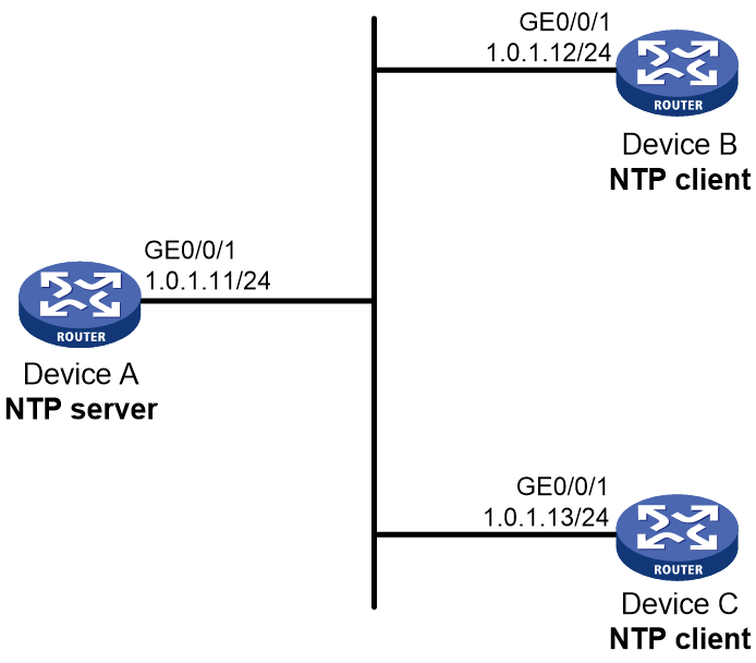
Network configuration
As shown in Figure 1, Device A on the network can be used as a time server to provide accurate time synchronization. Configure the NTP client/server mode to enable all devices to synchronize the time with Device A.
Software versions used
This configuration example was created and verified on R9141P16 of the MSR2630E-X1 router.
Procedure
Configuring Device A
# Assign an IP address to GigabitEthernet0/0/1.
<DeviceA> system-view
[DeviceA] interface gigabitethernet 0/0/1
[DeviceA-GigabitEthernet0/0/1] ip address 1.0.1.11 24
[DeviceA-GigabitEthernet0/0/1] quit
# Enable NTP.
[DeviceA] ntp-service enable
# Specify the local clock as the reference source, with stratum level 2.
[DeviceA] ntp-service refclock-master 2
Configuring Device B
# Assign IP addresses to interfaces. (Details not shown.).
# Enable NTP.
<DeviceB> system-view
[DeviceB] ntp-service enable
# Specify NTP for obtaining the system time.
[DeviceB] clock protocol ntp
# Specify Device A as the NTP server of Device B.
[DeviceB] ntp-service unicast-server 1.0.1.11
Configuring Device C
# Assign IP addresses to interfaces. (Details not shown.).
# Enable NTP.
<DeviceC> system-view
[DeviceC] ntp-service enable
# Specify NTP for obtaining the system time.
[DeviceC] clock protocol ntp
# Specify Device A as the NTP server of Device C.
[DeviceC] ntp-service unicast-server 1.0.1.11
Verifying the configuration
# Verify that Device B and Device C have synchronized the time with Device A. Device B is used in this example.
[DeviceB] display ntp-service status
Clock status: synchronized
Clock stratum: 3
System peer: 1.0.1.11
Local mode: client
Reference clock ID: 1.0.1.11
Leap indicator: 00
Clock jitter: 0.003479 s
Stability: 0.000 pps
Clock precision: 2^-16
Root delay: 1.95313 ms
Root dispersion: 28.38135 ms
Reference time: d5ed8cd5.577006ea Wed, Sep 25 2017 16:24:53.341
System poll interval: 8 s
The command output shows that Device B has synchronized the time with Device A. Its stratum level is 3, which is 1 stratum higher than Device A.
# Verify that an NTP association has been established between Device B and Device A.
[DeviceB] display ntp-service sessions
source reference stra reach poll now offset delay disper
********************************************************************************
[12345]1.0.1.11 127.127.1.0 2 255 64 38 -10.22 1.9531 3.3416
Notes: 1 source(master), 2 source(peer), 3 selected, 4 candidate, 5 configured.
Total sessions: 1
Configuration files
· Device A:
#
interface GigabitEthernet0/0/1
ip address 1.0.1.11 255.255.255.0
#
ntp-service enable
ntp-service refclock-master 2
#
· Device B:
#
interface GigabitEthernet0/0/1
ip address 1.0.1.12 255.255.255.0
#
clock protocol ntp
ntp-service enable
ntp-service unicast-server 1.0.1.11
#
· Device C:
#
interface GigabitEthernet0/0/1
ip address 1.0.1.13 255.255.255.0
#
clock protocol ntp
ntp-service enable
ntp-service unicast-server 1.0.1.11
#
Example: Configuring the IPv6 NTP client/server mode
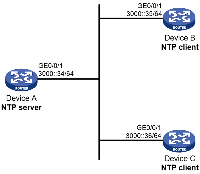
Network configuration
As shown in Figure 2, Device A on the IPv6 network can be used as a time server to provide accurate time synchronization. Configure the IPv6 NTP client/server mode to enable all devices to synchronize the time with Device A.
Software version used
This configuration example was created and verified on R9141P16 of the MSR2630E-X1 router.
Procedures
Configuring Device A
# Assign an IPv6 address to GigabitEthernet 0/0/1.
<DeviceA> system-view
[DeviceA] interface gigabitethernet 0/0/1
[DeviceA-GigabitEthernet0/0/1] ipv6 address 3000::34 64
[DeviceA-GigabitEthernet0/0/1] quit
# Enable the NTP service.
[DeviceA] ntp-service enable
# Specify the local clock as the reference source, with the stratum level 2.
[DeviceA] ntp-service refclock-master 2
Configuring Device B
# Assign an IPv6 address to the interface. (Details not shown.)
# Enable the NTP service.
<DeviceB> system-view
[DeviceB] ntp-service enable
# Specify NTP for obtaining the time.
[DeviceB] clock protocol ntp
# Specify Device A as the NTP server of Device B.
[DeviceB] ntp-service ipv6 unicast-server 3000::34
Configuring Device C
# Assign an IPv6 address to the interface. (Details not shown.)
# Enable the NTP service.
<DeviceC> system-view
[DeviceC] ntp-service enable
# Specify NTP for obtaining the time.
[DeviceC] clock protocol ntp
# Specify Device A as the NTP server of Device C.
[DeviceC] ntp-service ipv6 unicast-server 3000::34
Verifying the configuration
# Verify that Device B and Device C have synchronized the time with Device A. Device B is used in this example.
[DeviceB] display ntp-service status
Clock status: synchronized
Clock stratum: 3
System peer: 3000::34
Local mode: client
Reference clock ID: 95.197.17.40
Leap indicator: 00
Clock jitter: 0.003479 s
Stability: 0.000 pps
Clock precision: 2^-18
Root delay: 1.95313 ms
Root dispersion: 28.38135 ms
Reference time: d5ed8cd5.577006ea Wed, Sep 25 2013 16:24:53.341
System poll interval: 8 s
The command output shows that Device B has synchronized the time with Device A. Its stratum level is 3, which is 1 stratum higher than Device A.
# Verify that an IPv6 NTP association has been established between Device B and Device A.
[DeviceB] display ntp-service ipv6 sessions
Notes: 1 source(master), 2 source(peer), 3 selected, 4 candidate, 5 configured.
Source: [12345] 3000::34
Reference: 127.127.1.0 Clock stratum: 2
Reachabilities: 127 Poll interval: 64
Last receive time: 6 Offset: -0.123
Roundtrip delay: 0.3356 Dispersion: 5.3405
Total sessions: 1
Configuration files
· Device A:
#
interface GigabitEthernet0/0/1
ipv6 address 3000::34/64
#
ntp-service enable
ntp-service refclock-master 2
#
· Device B:
#
interface GigabitEthernet0/0/1
ipv6 address 3000::35/64
#
clock protocol ntp
ntp-service enable
ntp-service ipv6 unicast-server 3000::34
#
· Device C:
#
interface GigabitEthernet0/0/1
ipv6 address 3000::36/64
#
clock protocol ntp
ntp-service enable
ntp-service ipv6 unicast-server 3000::34
#
Example: Configuring NTP authentication in client/server association mode
Network configuration
Device A on the network can be used as a time server to provide accurate time synchronization. Configure the NTP client/server mode to enable all devices to synchronize the time with Device A.
· Configure Device A's local clock as its reference source, with stratum level 2.
· Configure Device B to operate in client mode and specify Device A as the NTP server of Device B.
· Configure NTP authentication on both Device A and Device B.
Figure 3 Network diagram

Software versions used
This configuration example was created and verified on R9141P16 of the MSR2630E-X1 router.
Procedure
Configuring Device A
# Specify an IP address for GigabitEthernet 0/0/1.
<DeviceA> system-view
[DeviceA] interface gigabitethernet 0/0/1
[DeviceA-GigabitEthernet0/0/1] ip address 1.0.1.11 24
[DeviceA-GigabitEthernet0/0/1] quit
# Enable the NTP service.
[DeviceA] ntp-service enable
# Specify the local clock as the reference source, with stratum level 2.
[DeviceA] ntp-service refclock-master 2
# Enable NTP authentication on Device A.
[DeviceA] ntp-service authentication enable
# Create authentication key 42 and set the key value of aNiceKey, in plain text.
[DeviceA] ntp-service authentication-keyid 42 authentication-mode md5 simple aNiceKey
# Specify key 42 as a trusted key.
[DeviceA] ntp-service reliable authentication-keyid 42
Configuring Device B
# Assign IP addresses to interfaces. (Details not shown.).
# Enable the NTP service.
<DeviceB> system-view
[DeviceB] ntp-service enable
# Specify NTP for obtaining the system time.
[DeviceB] clock protocol ntp
# Enable NTP authentication on Device B.
[DeviceB] ntp-service authentication enable
# Create authentication key 42 and set the key value of aNiceKey, in plain text.
[DeviceB] ntp-service authentication-keyid 42 authentication-mode md5 simple aNiceKey
# Specify key 42 as a trusted key.
[DeviceB] ntp-service reliable authentication-keyid 42
# Specify Device A as the NTP server of Device B, and associate the server with key 42.
[DeviceB] ntp-service unicast-server 1.0.1.11 authentication-keyid 42
Configuring Device C
# Assign IP addresses to interfaces. (Details not shown.).
# Enable the NTP service.
<DeviceC> system-view
[DeviceC] ntp-service enable
# Specify NTP for obtaining the system time.
[DeviceC] clock protocol ntp
# Enable NTP authentication on Device C.
[DeviceC] ntp-service authentication enable
# Create authentication key 42 and set the key value of aNiceKey, in plain text.
[DeviceC] ntp-service authentication-keyid 42 authentication-mode md5 simple aNiceKey
# Specify key 42 as a trusted key.
[DeviceC] ntp-service reliable authentication-keyid 42
# Specify Device A as the NTP server of Device C, and associate the server with key 42.
[DeviceC] ntp-service unicast-server 1.0.1.11 authentication-keyid 42
Verifying the configuration
# Verify that Device B has synchronized its time with Device A, and the clock stratum level of Device B is 3.
[DeviceB] display ntp-service status
Clock status: synchronized
Clock stratum: 3
System peer: 1.0.1.11
Local mode: client
Reference clock ID: 1.0.1.11
Leap indicator: 00
Clock jitter: 0.005096 s
Stability: 0.000 pps
Clock precision: 2^-16
Root delay: 0.00655 ms
Root dispersion: 1.15869 ms
Reference time: d0c62687.ab1bba7d Mon, Sep 30 2017 16:06:26.764
System poll interval: 8 s
# Verify that an IPv4 NTP association has been established between Device B and Device A.
[DeviceB] display ntp-service sessions
source reference stra reach poll now offset delay disper
********************************************************************************
[1245]1.0.1.11 127.127.1.0 2 1 64 519 -0.0 0.0065 0.0
Notes: 1 source(master),2 source(peer),3 selected,4 candidate,5 configured.
Total sessions : 1
Configuration files
· Device A:
#
interface GigabitEthernet0/0/1
ip address 1.0.1.11 255.255.255.0
#
ntp-service enable
ntp-service authentication enable
ntp-service authentication-keyid 42 authentication-mode md5 cipher $c$3$4j3SKCgQWBK3Un41B9U0JXzJX9i7IuNoSqi
ntp-service reliable authentication-keyid 42
ntp-service refclock-master 2
#
· Device B:
#
interface GigabitEthernet0/0/1
ip address 1.0.1.12 255.255.255.0
#
clock protocol ntp
ntp-service enable
ntp-service authentication enable
ntp-service authentication-keyid 42 authentication-mode md5 cipher $c$3$22eIc8l796cpudZqiaAZ2SLzIfrgzFTVYn8X
ntp-service reliable authentication-keyid 42
ntp-service unicast-server 1.0.1.11 authentication-keyid 42
#
· Device C:
#
interface GigabitEthernet0/0/1
ip address 1.0.1.13 255.255.255.0
#
clock protocol ntp
ntp-service enable
ntp-service authentication enable
ntp-service authentication-keyid 42 authentication-mode md5 cipher $c$3$XJzVmJ1TJbWyYAXpPXxF7JiEOZag8CehibM8
ntp-service reliable authentication-keyid 42
ntp-service unicast-server 1.0.1.11 authentication-keyid 42
#
Example: Configuring NTP multicast association mode
Network configuration
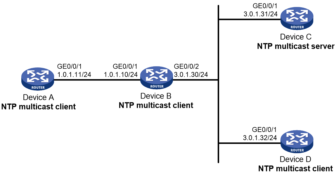
As shown in Figure 4, configure Device C as the NTP server for multiple devices on different network segments so that these devices synchronize the time with Device C.
Software versions used
This configuration example was created and verified on R9141P16 of the MSR2630E-X1 router.
Procedure
Assign an IP address to each interface, and make sure the devices can reach each other, as shown in Figure 4. (Details not shown.)
Configuring Device C
# Enable NTP.
<DeviceC> system-view
[DeviceC] ntp-service enable
# Specify the local clock as the reference source, with stratum level 2.
[DeviceC] ntp-service refclock-master 2
# Assign an IP address to GigabitEthernet 0/0/1.
[DeviceC] interface gigabitethernet 0/0/1
[DeviceC-GigabitEthernet0/0/1] ip address 3.0.1.31 24
# Configure Device C to operate in multicast server mode and send multicast messages from GigabitEthernet 0/0/1.
[DeviceC-GigabitEthernet0/0/1] ntp-service multicast-server
[DeviceC-GigabitEthernet0/0/1] quit
Configuring Device D
# Enable NTP.
<DeviceD> system-view
[DeviceD] ntp-service enable
# Specify NTP for obtaining the system time.
[DeviceD] clock protocol ntp
# Assign an IP address to GigabitEthernet 0/0/1.
[DeviceD] interface gigabitethernet 0/0/1
[DeviceD-GigabitEthernet0/0/1] ip address 3.0.1.32 24
# Configure Device D to operate in multicast client mode and receive multicast messages on GigabitEthernet 0/0/1.
[DeviceD-GigabitEthernet0/0/1] ntp-service multicast-client
[DeviceD-GigabitEthernet0/0/1] quit
Configuring Device B
# Enable NTP.
<DeviceB> system-view
[DeviceB] ntp-service enable
# Specify NTP for obtaining the system time.
[DeviceB] clock protocol ntp
# Configure Device B to operate in multicast client mode and receive multicast messages on GigabitEthernet 0/0/2.
[DeviceB] interface gigabitethernet 0/0/2
[DeviceB-GigabitEthernet0/0/2] ip address 3.0.1.30 24
[DeviceB-GigabitEthernet0/0/2] ntp-service multicast-client
[DeviceB-GigabitEthernet0/0/2] quit
Because Device A and Device C are on different subnets, you must enable the multicast functions on Device B before Device A can receive multicast messages from Device C.
# Enable the IP multicast function.
[DeviceB] multicast routing
[DeviceB-mrib] quit
[DeviceB] interface gigabitethernet 0/0/2
[DeviceB-GigabitEthernet0/0/2] pim dm
[DeviceB-GigabitEthernet0/0/2] quit
[DeviceB] interface gigabitethernet 0/0/1
[DeviceB-GigabitEthernet0/0/1] ip address 1.0.1.10 24
[DeviceB-GigabitEthernet0/0/1] igmp enable
[DeviceB-GigabitEthernet0/0/1] igmp static-group 224.0.1.1
[DeviceB-GigabitEthernet0/0/1] quit
Configuring Device A
# Enable NTP.
<DeviceA> system-view
[DeviceA] ntp-service enable
# Specify NTP for obtaining the system time.
[DeviceA] clock protocol ntp
# Assign an IP address to GigabitEthernet 0/0/1.
[DeviceA] interface gigabitethernet 0/0/1
[DeviceA-GigabitEthernet0/0/1] ip address 1.0.1.11 24
# Configure Device A to operate in multicast client mode and receive multicast messages on GigabitEthernet 0/0/1.
[DeviceA-GigabitEthernet0/0/1] ntp-service multicast-client
[DeviceA-GigabitEthernet0/0/1] quit
Verifying the configuration
# Verify that Device A has synchronized its time with Device C, and the clock stratum level of Device A is 3.
[DeviceA] display ntp-service status
Clock status: synchronized
Clock stratum: 3
System peer: 3.0.1.31
Local mode: bclient
Reference clock ID: 3.0.1.31
Leap indicator: 00
Clock jitter: 0.000061 s
Stability: 0.000 pps
Clock precision: 2^-16
Root delay: 1.69373 ms
Root dispersion: 1950.18005 ms
Reference time: d5ee9b15.2f3a684d Thu, Sep 26 2017 11:37:57.184
System poll interval: 8 s
The command output shows that Device A has synchronized the time with Device C. Its stratum level is 3, which is 1 stratum higher than Device C.
Configuration files
· Device A:
#
clock protocol ntp
ntp-service enable
#
interface GigabitEthernet0/0/1
ip address 1.0.1.11 255.255.255.0
ntp-service multicast-client
#
· Device B:
#
clock protocol ntp
ntp-service enable
#
multicast routing
#
interface GigabitEthernet0/0/2
ip address 3.0.1.30 255.255.255.0
pim dm
ntp-service multicast-client
#
interface GigabitEthernet0/0/1
ip address 1.0.1.10 255.255.255.0
igmp enable
igmp static-group 224.0.1.1
#
· Device C:
#
ntp-service enable
ntp-service refclock-master 2
#
interface GigabitEthernet0/0/1
ip address 3.0.1.31 255.255.255.0
ntp-service multicast-server
#
· Device D:
#
clock protocol ntp
ntp-service enable
#
interface GigabitEthernet0/0/1
ip address 3.0.1.32 255.255.255.0
ntp-service multicast-client
#
Example: Configuring the IPv6 NTP multicast mode
Network configuration
As shown in Figure 5, the IPv6 network has many devices distributed on different subnets. Device C on the network can be used as a time server to provide accurate time synchronization. Configure the IPv6 NTP multicast mode to enable all devices to synchronize the time with Device C.

Software version used
This configuration example was created and verified on R9141P16 of the MSR2630E-X1 router.
Procedures
Configuring Device C
# Configure routing protocols so that all devices can reach each other. (Details not shown.)
# Enable the NTP service.
<DeviceC> system-view
[DeviceC] ntp-service enable
# Specify the local clock as the reference source, with the stratum level 2.
[DeviceC] ntp-service refclock-master 2
# Assign an IPv6 address to GigabitEthernet 0/0/1.
[DeviceC] interface gigabitethernet 0/0/1
[DeviceC-GigabitEthernet0/0/1] ipv6 address 3000::2 64
# Configure Device C to operate in IPv6 multicast server mode and send multicast messages from GigabitEthernet 0/0/1 to multicast address FF24::1.
[DeviceC-GigabitEthernet0/0/1] ntp-service ipv6 multicast-server ff24::1
[DeviceC-GigabitEthernet0/0/1] quit
Configuring Device D
# Configure routing protocols and assign IP addresses to interfaces so that devices can reach each other. (Details not shown.)
# Enable the NTP service.
<DeviceD> system-view
[DeviceD] ntp-service enable
# Configure Device D to operate in IPv6 multicast client mode and receive multicast messages on GigabitEthernet 0/0/1.
[DeviceD] interface gigabitethernet 0/0/1
[DeviceD-GigabitEthernet0/0/1] ntp-service ipv6 multicast-client ff24::1
[DeviceD-GigabitEthernet0/0/1] quit
Configuring Device B
# Configure routing protocols and assign an IP address to each interface so that devices can reach each other. (Details not shown.)
# Enable the NTP service.
<DeviceB> system-view
[DeviceB] ntp-service enable
# Configure Device B to operate in IPv6 multicast client mode and receive multicast messages on GigabitEthernet 0/0/2.
[DeviceB] interface gigabitethernet 0/0/2
[DeviceB-GigabitEthernet0/0/2] ntp-service ipv6 multicast-client ff24::1
[DeviceB-GigabitEthernet0/0/2] quit
Device A and Device C are on different subnets. For Device A to receive multicast messages from Device C, you must enable IPv6 multicast on Device B.
# Enable IPv6 multicast.
[DeviceB] ipv6 multicast routing
[DeviceB-mrib6] quit
[DeviceB] interface gigabitethernet 0/0/2
[DeviceB-GigabitEthernet0/0/2] ipv6 pim dm
[DeviceB-GigabitEthernet0/0/2] quit
[DeviceB] interface gigabitethernet 0/0/1
[DeviceB-GigabitEthernet0/0/1] mld enable
[DeviceB-GigabitEthernet0/0/1] mld static-group ff24::1
[DeviceB-GigabitEthernet0/0/1] quit
Configuring Device A
# Configure routing protocols and assign IP address to interfaces so that devices can reach each other. (Details not shown.)
# Enable the NTP service.
<DeviceA> system-view
[DeviceA] ntp-service enable
# Configure Device A to operate in IPv6 multicast client mode and receive multicast messages on GigabitEthernet 0/0/1.
[DeviceA] interface gigabitethernet 0/0/1
[DeviceA-GigabitEthernet0/0/1] ntp-service ipv6 multicast-client ff24::1
[DeviceA-GigabitEthernet0/0/1] quit
Verifying the configuration
# Verify that the devices have synchronized the time with Device C. Device A is used an example.
[DeviceA] display ntp-service status
Clock status: synchronized
Clock stratum: 3
System peer: 3000::2
Local mode: bclient
Reference clock ID: 165.84.121.65
Leap indicator: 00
Clock jitter: 0.000061 s
Stability: 0.000 pps
Clock precision: 2^-18
Root delay: 1.69373 ms
Root dispersion: 1950.18005 ms
Reference time: d5ee9b15.2f3a684d Thu, Sep 26 2013 11:37:57.184
The command output shows that Device A has synchronized the time with Device C. Its stratum level is 3, which is 1 stratum higher than Device C.
Configuration files
· Device A:
#
ntp-service enable
#
interface GigabitEthernet0/0/1
ipv6 address 2000::1/64
ntp-service ipv6 multicast-client ff24::1
#
· Device B:
#
ntp-service enable
#
ipv6 multicast routing
#
mld-snooping
#
interface GigabitEthernet0/0/2
ipv6 address 3000::1/64
ipv6 pim dm
ntp-service ipv6 multicast-client ff24::1
#
interface GigabitEthernet0/0/1
ipv6 address 2000::2/64
mld enable
mld static-group ff24::1
#
· Device C:
#
ntp-service enable
ntp-service refclock-master 2
#
interface GigabitEthernet0/0/1
ipv6 address 3000::2/64
ntp-service ipv6 multicast-server ff24::1
#
· Device D:
#
ntp-service enable
#
interface GigabitEthernet0/0/1
ipv6 address 3000::3/64
ntp-service ipv6 multicast-client ff24::1
#
Example: Configuring NTP broadcast association mode
Network configuration
As shown in Figure 6, configure Device A as the NTP server of multiple devices on the same network segment so that these devices synchronize the time with Device A.

Software versions used
This configuration example was created and verified on R9141P16 of the MSR2630E-X1 router.
Procedures
Configuring Device A
# Enable NTP.
<DeviceA> system-view
[DeviceA] ntp-service enable
# Specify the local clock as the reference source, with stratum level 2.
[DeviceA] ntp-service refclock-master 2
# Assign an IP address to GigabitEthernet 0/0/1.
[DeviceA] interface gigabitethernet 0/0/1
[DeviceA-GigabitEthernet0/0/1] ip address 3.0.1.30 24
# Configure Device A to operate in broadcast server mode and send broadcast messages from GigabitEthernet 0/0/1.
[DeviceA-GigabitEthernet0/0/1] ntp-service broadcast-server
[DeviceA-GigabitEthernet0/0/1] quit
Configuring Device B
# Assign IP addresses to interfaces. (Details not shown.).
# Enable NTP.
<DeviceB> system-view
[DeviceB] ntp-service enable
# Specify NTP for obtaining the system time.
[DeviceB] clock protocol ntp
# Configure Device B to operate in broadcast client mode and receive broadcast messages on GigabitEthernet 0/0/1.
[DeviceB] interface gigabitethernet 0/0/1
[DeviceB-GigabitEthernet0/0/1] ntp-service broadcast-client
[DeviceB-GigabitEthernet0/0/1] quit
# Configure Device C in the same way Device B is configured. (Details not shown.)
Verifying the configuration
The following procedure uses Device B as an example to verify the configuration.
# Verify that Device B has synchronized its time with Device A, and the clock stratum level of Device B is 3.
[DeviceB] display ntp-service status
Clock status: synchronized
Clock stratum: 3
System peer: 3.0.1.30
Local mode: bclient
Reference clock ID: 3.0.1.30
Leap indicator: 00
Clock jitter: 0.000061 s
Stability: 0.000 pps
Clock precision: 2^-16
Root delay: 0.00000 ms
Root dispersion: 7951.43127 ms
Reference time: d5ee8d88.2faabed0 Thu, Sep 26 2017 10:40:08.186
System poll interval: 8 s
The command output shows that Device B has synchronized the time with Device A. Its stratum level is 3, which is 1 stratum higher than Device A.
# Verify that an NTP association has been established between Device B and Device A.
[DeviceB] display ntp-service sessions
source reference stra reach poll now offset delay disper
********************************************************************************
[1234]3.0.1.30 127.127.1.0 2 254 64 82 -2.190 0.0000 7937.5
Notes: 1 source(master), 2 source(peer), 3 selected, 4 candidate, 5 configured.
Total sessions: 1
Configuration files
· Device A:
#
interface GigabitEthernet0/0/1
ip address 3.0.1.30 255.255.255.0
ntp-service broadcast-server
#
ntp-service enable
ntp-service refclock-master 2
#
· Device B:
#
interface GigabitEthernet0/0/1
ip address 3.0.1.31 255.255.255.0
ntp-service broadcast-client
#
clock protocol ntp
ntp-service enable
#
· Device C:
#
interface GigabitEthernet0/0/1
ip address 3.0.1.32 255.255.255.0
ntp-service broadcast-client
#
clock protocol ntp
ntp-service enable
#
Example: Configuring the NTP broadcast mode with authentication
Network configuration
As shown in Figure 7, many devices are on the network and all of them are on the same network segment (3.0.1.0/24).
· Configure the NTP broadcast mode to ensure that all devices in the network have consistent time.
· To ensure secure clock synchronization and prevent attackers from disguising themselves as clock servers and launching attacks on device clocks, configure NTP authentication so that authentication is performed before time synchronization.

Software version used
This configuration example was created and verified on Release 6749 of the MSR3610-X1 router.
This configuration example was created and verified on R9141P16 of the MSR2630E-X1 router.
Procedures
Configure Device A
# Enable the NTP service.
<DeviceA> system-view
[DeviceA] ntp-service enable
# Specify the local clock as the reference source, with the stratum level 2.
[DeviceA] ntp-service refclock-master 2
# Enable NTP authentication. Configure an NTP authentication key, with the key ID of 88 and key value of 123456.
[DeviceA] ntp-service authentication enable
[DeviceA] ntp-service authentication-keyid 88 authentication-mode md5 simple 123456
[DeviceA] ntp-service reliable authentication-keyid 88
# Specify Device A as an NTP broadcast server, and associate key 88 with Device A.
[DeviceA] interface gigabitethernet 0/0/1
[DeviceA-GigabitEthernet0/0/1] ip address 3.0.1.30 24
[DeviceA-GigabitEthernet0/0/1] ntp-service broadcast-server authentication-keyid 88
[DeviceA-GigabitEthernet0/0/1] quit
Configure Device B
# Enable the NTP service.
<DeviceB> system-view
[DeviceB] ntp-service enable
# Enable NTP authentication. Specify exactly the same authentication key ID and key as Device A.
[DeviceB] ntp-service authentication enable
[DeviceB] ntp-service authentication-keyid 88 authentication-mode md5 simple 123456
[DeviceB] ntp-service reliable authentication-keyid 88
# Configure Device B to operate in NTP broadcast client mode and receive NTP broadcast messages on GigabitEthernet 0/0/1.
[DeviceB] interface gigabitethernet 0/0/1
[DeviceB-GigabitEthernet0/0/1] ntp-service broadcast-client
[DeviceB-GigabitEthernet0/0/1] ip address 3.0.1.31 24
[DeviceB-GigabitEthernet0/0/1] quit
# Configure Device C in the same way Device B is configured. (Details not shown.)
Verifying the configuration
# Verify that the devices have synchronized the time with Device A. Device B is used an example.
[DeviceA] display ntp-service status
Clock status: synchronized
Clock stratum: 3
System peer: 3.0.1.30
Local mode: bclient
Reference clock ID: 3.0.1.30
Leap indicator: 00
Clock jitter: 0.000092 s
Stability: 0.000 pps
Clock precision: 2^-18
Root delay: 2.42615 ms
Root dispersion: 1950.98877 ms
Reference time: d5eed631.2f498d71 Thu, Sep 26 2013 15:50:09.184
The command output shows that Device B has synchronized the time with Device A. Its stratum level is 3, which is 1 stratum higher than Device A.
Configuration files
· Device A:
#
interface GigabitEthernet0/0/1
ip address 3.0.1.30 255.255.255.0
ntp-service broadcast-server authentication-keyid 88
#
ntp-service enable
ntp-service authentication enable
ntp-service authentication-keyid 88 authentication-mode md5 cipher $c$3$iJudDKiqCVO+gOaG53
63/fz4M3dQvHo2Fw==
ntp-service reliable authentication-keyid 88
ntp-service refclock-master 2
#
· Device B and Device C:
#
interface GigabitEthernet0/0/1
ip address 3.0.1.31 255.255.255.0
ntp-service broadcast-client
#
ntp-service enable
ntp-service authentication enable
ntp-service authentication-keyid 88 authentication-mode md5 cipher $c$3$pU6KvpS80MadhM2zM
CCSR07HX4qEbJhHvQ==
ntp-service reliable authentication-keyid 88
SNTP configuration examples
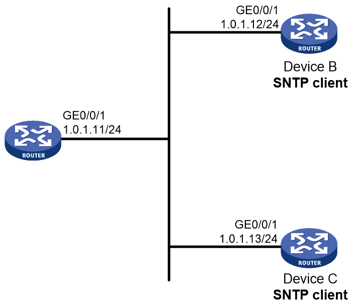
Network configuration
As shown in Figure 8, Device A on the network can be used as a time server Network to provide accurate time synchronization. Configure the client/server mode to enable all devices to synchronize the time with Device A.
Software versions used
This configuration example was created and verified on R9141P16 of the MSR2630E-X1 router.
Procedure
Configuring Device A
# Assign an IP address to GigabitEthernet 0/0/1.
<DeviceA> system-view
[DeviceA] interface gigabitethernet 0/0/1
[DeviceA-GigabitEthernet0/0/1] ip address 1.0.1.11 24
[DeviceA-GigabitEthernet0/0/1] quit
# Enable NTP.
[DeviceA] ntp-service enable
# Specify the local clock as the reference source, with stratum level 2.
[DeviceA] ntp-service refclock-master 2
Configuring Device B
# Assign IP addresses to interfaces. (Details not shown.).
# Enable SNTP.
<DeviceB> system-view
[DeviceB] sntp enable
# Specify NTP for obtaining the system time.
[DeviceB] clock protocol ntp
# Specify Device A as the NTP server of Device B.
[DeviceB] sntp unicast-server 1.0.1.11
Configuring Device C
# Assign IP addresses to interfaces. (Details not shown.).
# Enable SNTP.
<DeviceC> system-view
[DeviceC] sntp enable
# Specify NTP for obtaining the system time.
[DeviceC] clock protocol ntp
# Specify Device A as the NTP server of Device C.
[DeviceC] sntp unicast-server 1.0.1.11
Verifying the configuration
# Verify that an SNTP association has been established between Device B and Device A, and Device B has synchronized its time with Device A.
[DeviceB] display sntp sessions
SNTP server Stratum Version Last receive time
1.0.1.11 2 4 Thu, Sep 26 2017 17:25:09.121 (Synced)
Configuration files
· Device A:
#
interface GigabitEthernet0/0/1
ip address 1.0.1.11 255.255.255.0
#
ntp-service enable
ntp-service refclock-master 2
#
· Device B:
#
interface GigabitEthernet0/0/1
ip address 1.0.1.12 255.255.255.0
#
clock protocol ntp
sntp enable
sntp unicast-server 1.0.1.11
#
· Device C:
#
interface GigabitEthernet0/0/1
ip address 1.0.1.13 255.255.255.0
#
clock protocol ntp
sntp enable
sntp unicast-server 1.0.1.11
#
Related documentation
· Network Management and Monitoring Configuration Guide in H3C MSR1000[2600][3600] Routers Configuration Guides (V9)
· Network Management and Monitoring Command Reference in MSR1000[2600][3600] Routers Command References (V9)