- Table of Contents
-
- H3C MSR1000[2600][3600] Routers Configuration Examples All-in-One-R9141-6W100
- 00-Preface
- 01-Local 802.1X Authentication Configuration Examples
- 02-RADIUS-Based 802.1X Authentication Configuration Examples
- 03-AAA Configuration Examples
- 04-ACL Configuration Examples
- 05-MPLS over ADVPN Configuration Examples
- 06-ARP Attack Protection Configuration Examples
- 07-BFD Configuration Examples
- 08-Basic BGP Configuration Examples
- 09-BGP Route Attribute-Based Route Selection Configuration Examples
- 10-EAA Monitor Policy Configuration Examples
- 11-GRE with OSPF Configuration Examples
- 12-HoVPN Configuration Examples
- 13-IGMP Snooping Configuration Examples
- 14-IGMP Configuration Examples
- 15-IPsec Configuration Examples
- 16-IPsec Digital Certificate Authentication Configuration Examples
- 17-IPv6 IS-IS Configuration Examples
- 18-IPv6 over IPv4 GRE Tunnel Configuration Examples
- 19-IPv6 over IPv4 Manual Tunnel with OSPFv3 Configuration Examples
- 20-IS-IS Configuration Examples
- 21-Combined ISATAP Tunnel and 6to4 Tunnel Configuration Examples
- 22-L2TP over IPsec Configuration Examples
- 23-Multi-Instance L2TP Configuration Examples
- 24-L2TP Multidomain Access Configuration Examples
- 25-MPLS L3VPN Configuration Examples
- 26-MPLS OAM Configuration Examples
- 27-MPLS TE Configuration Examples
- 28-Basic MPLS Configuration Examples
- 29-NAT DNS Mapping Configuration Examples
- 30-NetStream Configuration Examples
- 31-NQA Configuration Examples
- 32-NTP Configuration Examples
- 33-OSPFv3 Configuration Examples
- 34-OSPF Configuration Examples
- 35-OSPF Multi-Process Configuration Examples
- 36-OSPF Multi-Instance Configuration Examples
- 37-Portal Configuration Examples
- 38-PPP Configuration Examples
- 39-RBAC Configuration Examples
- 40-RMON Configuration Examples
- 41-IPv4 NetStream Sampling Configuration Examples
- 42-SNMP Configuration Examples
- 43-SRv6 Configuration Examples
- 44-SSH Configuration Examples
- 45-Tcl Commands Configuration Examples
- 46-VLAN Configuration Examples
- 47-VRRP Configuration Examples
- 48-VXLAN over IPsec Configuration Examples
- 49-WLAN AC Configuration Examples
- 50-Small and Medium-Sized Store Configuration Examples
- 51-Cloudnet VPN Configuration Examples
- 52-Ethernet Link Aggregation Configuration Examples
- 53-Ethernet OAM Configuration Examples
- 54-Outbound Bidirectional NAT Configuration Examples
- 55-NAT Hairpin in C-S Mode Configuration Examples
- 56-Load Sharing NAT Server Configuration Examples
- 57-BIDIR-PIM Configuration Examples
- 58-Control Plane-Based QoS Policy Configuration Examples
- 59-Scheduling a Task Configuration Examples
- 60-Client-Initiated L2TP Tunnel Configuration Examples
- 61-LAC-Auto-Initiated L2TP Tunnel Configuration Examples
- 62-Authorized ARP Configuration Examples
- 63-GTS Configuration Examples
- 64-Traffic Policing Configuration Examples
- 65-Traffic Accounting Configuration Examples
- 66-Mobile Communication Modem Management Configuration Examples
- 67-Port Isolation Configuration Examples
- 68-PBR Configuration Examples
- 69-TFTP Client Software Upgrade Configuration Examples
- 70-FTP Client Software Upgrade Configuration Examples
- 71-FTP Server Software Upgrade Configuration Examples
- 72-Routing Policy Configuration Examples
- 73-Software Upgrade from the BootWare Menu Configuration Examples
- 74-Mirroring Configuration Examples
- Related Documents
-
| Title | Size | Download |
|---|---|---|
| 12-HoVPN Configuration Examples | 175.75 KB |
|
|
|
H3C Routers |
|
HoVPN Configuration Examples |
|
|
|
|
Copyright © 2024 New H3C Technologies Co., Ltd. All rights reserved.
No part of this manual may be reproduced or transmitted in any form or by any means without prior written consent of New H3C Technologies Co., Ltd.
Except for the trademarks of New H3C Technologies Co., Ltd., any trademarks that may be mentioned in this document are the property of their respective owners.
The information in this document is subject to change without notice.
Contents
Introduction
The following information provides MPLS HoVPN configuration examples.
Prerequisites
The following information applies to Comware 9-based routers. Procedures and information in the examples might be slightly different depending on the software or hardware version of the routers.
The configuration examples were created and verified in a lab environment, and all the devices were started with the factory default configuration. When you are working on a live network, make sure you understand the potential impact of every command on your network.
The following information is provided based on the assumption that you have basic knowledge of HoVPN.
Example: Configure MPLS HoVPN
Network configuration
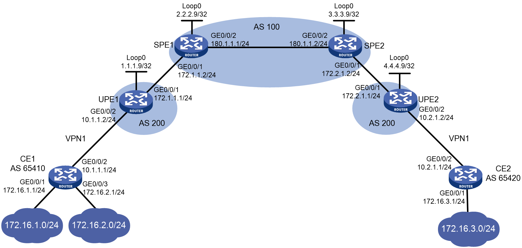
As shown in Figure 1, the SPE devices are ISP backbone devices in AS 100. The UPE devices are user-facing devices in AS 200. UPE 1 and UPE 2 are connected to CE 1 and CE 2 of VPN1, respectively. CE 1 is connected to two subnets 172.16.1.0/24 and 172.16.2.0/24. CE 2 is connected to subnet 172.16.3.0/24.
Configure HoVPN for the user networks, and configure routing policies to control user access as follows: allow access between CE 1’s 172.16.1.0/24 and CE 2’s 172.16.3.0/24 and deny access between CE 1’s 172.16.2.0/24 and CE 2's 172.16.3.0/24.
Analysis
The configuration mainly includes two parts:
· Configure the HoVPN service on the network.
· Configure routing policies on SPE devices and configure SPE 2 to advertise only the 172.16.1.0/24 network of CE 1 to UPE 2.
Software versions used
This configuration example was created and verified on R9141P16 of the MSR2630E-X1 device.
Restrictions and guidelines
· In an HoVPN network, the routing policy configuration is required. For an SPE to advertise routes to a UPE, you must configure a routing policy on the SPE and enable the SPE to advertise routes to the UPE.
· When you configure an EBGP peer relationship between an SPE and a UPE to advertise labeled routes, you must enable the label exchange capability between the peers and then configure a routing policy to label the routes advertised to the peer. If you only enable the label exchange capability, routes cannot be advertised to the peer with labels.
· When an interface is bound to a VPN instance, the settings (including IP address) on the interface will be cleared. Therefore, bind an interface to a VPN instance before you configure other settings on the interface.
Procedures
Configuring MPLS, MPLS LDP, and OSPF on SPEs
1. Configure SPE 1:
# Configure the Loopback interface address.
<SPE1>system-view
[SPE1] interface loopback 0
[SPE1-LoopBack0] ip address 2.2.2.9 32
[SPE1-LoopBack0] quit
# Configure the MPLS LSR ID and enable LDP globally.
[SPE1] mpls lsr-id 2.2.2.9
[SPE1] mpls ldp
[SPE1-ldp] quit
# Configure an IP address and enable MPLS on interface GigabitEthernet 0/0/1.
[SPE1] interface gigabitethernet 0/0/1
[SPE1-GigabitEthernet0/0/1] ip address 172.1.1.2 24
[SPE1-GigabitEthernet0/0/1] mpls enable
[SPE1-GigabitEthernet0/0/1] quit
# Configure an IP address, and enable MPLS and IPv4 LDP capabilities on interface GigabitEthernet 0/0/2.
[SPE1] interface gigabitethernet 0/0/2
[SPE1-GigabitEthernet0/0/2] ip address 180.1.1.1 24
[SPE1-GigabitEthernet0/0/2] mpls enable
[SPE1-GigabitEthernet0/0/2] mpls ldp enable
[SPE1-GigabitEthernet0/0/2] quit
# Configure OSPF as the IGP to ensure IP connectivity on the backbone network.
[SPE1]ospf 1
[SPE1-ospf-1] area 0
[SPE1-ospf-1-area-0.0.0.0] network 2.2.2.9 0.0.0.0
[SPE1-ospf-1-area-0.0.0.0] network 180.1.1.0 0.0.0.255
[SPE1-ospf-1-area-0.0.0.0] quit
[SPE1-ospf-1] quit
2. Configure SPE 2:
# Configure the Loopback interface address.
<SPE2>system-view
[SPE2] interface loopback 0
[SPE2-LoopBack0] ip address 3.3.3.9 32
[SPE2-LoopBack0] quit
# Configure the MPLS LSR ID and enable LDP globally.
[SPE2] mpls lsr-id 3.3.3.9
[SPE2] mpls ldp
[SPE2-ldp] quit
# Configure an IP address, and enable MPLS and IPv4 LDP capabilities on interface GigabitEthernet 1/0/2.
[SPE2] interface gigabitethernet 0/0/2
[SPE2-GigabitEthernet0/0/2] ip address 180.1.1.2 24
[SPE2-GigabitEthernet0/0/2] mpls enable
[SPE2-GigabitEthernet0/0/2] mpls ldp enable
[SPE2-GigabitEthernet0/0/2] quit
# Configure an IP address and enable MPLS on interface GigabitEthernet 0/0/1.
[SPE2] interface gigabitethernet 0/0/1
[SPE2-GigabitEthernet0/0/1] ip address 172.2.1.2 24
[SPE2-GigabitEthernet0/0/1] mpls enable
[SPE2-GigabitEthernet0/0/1] quit
# Configure OSPF as the IGP to ensure IP connectivity on the backbone network.
[SPE2]ospf 1
[SPE2-ospf-1] area 0
[SPE2-ospf-1-area-0.0.0.0] network 3.3.3.9 0.0.0.0
[SPE2-ospf-1-area-0.0.0.0] network 180.1.1.0 0.0.0.255
[SPE2-ospf-1-area-0.0.0.0] quit
[SPE2-ospf-1] quit
After the configuration is completed, execute the display mpls ldp peer command on SPE 1 to verify that an LDP session has been established in Operational state. Execute the display ospf peer command on SPE 1 to verify that an OSPF neighbor relationship has been established in Full state.
Configuring MP-IBGP peering between SPEs to exchange VPNv4 routes
# Configure SPE 1 to establish MP-IBGP peering with SPE 2 to exchange VPNv4 routes.
[SPE1] bgp 100
[SPE1-bgp] peer 3.3.3.9 as-number 100
[SPE1-bgp] peer 3.3.3.9 connect-interface loopback 0
[SPE1-bgp] address-family vpnv4
[SPE1-bgp-vpnv4] peer 3.3.3.9 enable
[SPE1-bgp-vpnv4] quit
[SPE1-bgp] quit
# Configure SPE 2 to establish MP-IBGP peering with SPE 1 to exchange VPNv4 routes.
[SPE2] bgp 100
[SPE2-bgp] peer 2.2.2.9 as-number 100
[SPE2-bgp] peer 2.2.2.9 connect-interface loopback 0
[SPE2-bgp] address-family vpnv4
[SPE2-bgp-vpnv4] peer 2.2.2.9 enable
[SPE2-bgp-vpnv4] quit
[SPE2-bgp] quit
After the configuration is completed, execute the display bgp peer vpnv4 command on SPE 1 and SPE 2 to verify that a BGP peer relationship has been established between the SPEs and is in Established state.
Enabling MPLS on UPEs
1. Configure UPE 1:
# Configure the Loopback interface address.
<UPE1>system-view
[UPE1] interface loopback 0
[UPE1-LoopBack0] ip address 1.1.1.9 32
[UPE1-LoopBack0] quit
# Configure the MPLS LSR ID for the device.
[UPE1] mpls lsr-id 1.1.1.9
# Configure an IP address and enable MPLS on interface GigabitEthernet 0/0/1.
[UPE1] interface gigabitethernet 0/0/1
[UPE1-GigabitEthernet0/0/1] ip address 172.1.1.1 24
[UPE1-GigabitEthernet0/0/1] mpls enable
[UPE1-GigabitEthernet0/0/1] quit
2. Configure UPE 2:
# Configure the Loopback interface address.
<UPE2>system-view
[UPE2] interface loopback 0
[UPE2-Loopback0] ip address 4.4.4.9 32
[UPE2-Loopback0] quit
# Configure the MPLS LSR ID for the device.
[UPE2] mpls lsr-id 4.4.4.9
# Configure an IP address and enable MPLS on interface GigabitEthernet 0/0/1.
[UPE2] interface gigabitethernet 0/0/1
[UPE2-GigabitEthernet0/0/1] ip address 172.2.1.1 24
[UPE2-GigabitEthernet0/0/1] mpls enable
[UPE2-GigabitEthernet0/0/1] quit
Configuring EBGP peering between SPEs and UPEs to exchange labeled routes and establish BGP LSPs
1. Configure SPE 1:
# Establish EBGP peering with UPE 1.
[SPE1] bgp 100
[SPE1-bgp] peer 172.1.1.1 as-number 200
# In BGP IPv4 unicast address family view, enable the capability of exchanging labeled IPv4 routes with the peer.
[SPE1-bgp] address-family ipv4
[SPE1-bgp-ipv4] peer 172.1.1.1 enable
[SPE1-bgp-ipv4] peer 172.1.1.1 label-route-capability
# Apply routing policy policy1 to the routes to be advertised to the peer.
[SPE1-bgp-ipv4] peer 172.1.1.1 route-policy policy1 export
[SPE1-bgp-ipv4] network 2.2.2.9 255.255.255.255
[SPE1-bgp-ipv4] quit
[SPE1-bgp] quit
# Configure the routing policy to allocate labels to routes.
[SPE1] route-policy policy1 permit node 0
[SPE1-route-policy-policy1-0] apply mpls-label
[SPE1-route-policy-policy1-0] quit
2. Configure UPE 1:
# Establish EBGP peering with UPE 1.
[UPE1] bgp 200
[UPE1-bgp] peer 172.1.1.2 as-number 100
# In BGP IPv4 unicast address family view, enable the capability of exchanging labeled IPv4 routes with the peer.
[UPE1-bgp] address-family ipv4
[UPE1-bgp-ipv4] peer 172.1.1.2 enable
[UPE1-bgp-ipv4] peer 172.1.1.2 label-route-capability
# Apply routing policy policy1 to the routes to be advertised to the peer.
[UPE1-bgp-ipv4] peer 172.1.1.2 route-policy policy1 export
[UPE1-bgp-ipv4] network 1.1.1.9 255.255.255.255
[UPE1-bgp-ipv4] quit
[UPE1-bgp] quit
# Configure the routing policy to allocate labels to routes.
[UPE1] route-policy policy1 permit node 0
[UPE1-route-policy-policy1-0] apply mpls-label
[UPE1-route-policy-policy1-0] quit
3. Configure SPE 2:
Establish EBGP peering with UPE 2.
[SPE2] bgp 100
[SPE2-bgp] peer 172.2.1.1 as-number 200
# In BGP IPv4 unicast address family view, enable the capability of exchanging labeled IPv4 routes with the peer.
[SPE2-bgp] address-family ipv4
[SPE2-bgp-ipv4] peer 172.2.1.1 enable
[SPE2-bgp-ipv4] peer 172.2.1.1 label-route-capability
# Apply routing policy policy1 to the routes to be advertised to the peer.
[SPE2-bgp-ipv4] peer 172.2.1.1 route-policy policy1 export
[SPE2-bgp-ipv4] network 3.3.3.9 255.255.255.255
[SPE2-bgp-ipv4] quit
[SPE2-bgp] quit
# Configure the routing policy to allocate labels to routes.
[SPE2] route-policy policy1 permit node 0
[SPE2-route-policy-policy1-0] apply mpls-label
[SPE2-route-policy-policy1-0] quit
4. Configure UPE 2:
# Establish EBGP peering with UPE 2.
[UPE2] bgp 200
[UPE2-bgp] peer 172.2.1.2 as-number 100
# In BGP IPv4 unicast address family view, enable the capability of exchanging labeled IPv4 routes with the peer.
[UPE2-bgp] address-family ipv4
[UPE2-bgp-ipv4] peer 172.2.1.2 enable
[UPE2-bgp-ipv4] peer 172.2.1.2 label-route-capability
# Apply routing policy policy1 to the routes to be advertised to the peer.
[UPE2-bgp-ipv4] peer 172.2.1.2 route-policy policy1 export
[UPE2-bgp-ipv4] network 4.4.4.9 255.255.255.255
[UPE2-bgp-ipv4] quit
[UPE2-bgp] quit
# Configure the routing policy to allocate labels to routes.
[UPE2] route-policy policy1 permit node 0
[UPE2-route-policy-policy1-0] apply mpls-label
[UPE2-route-policy-policy1-0] quit
After the configuration is completed, execute the display mpls lsp command on each device to verify that BGP LSPs have been established between SPEs and UPEs.
Configuring MP-EBGP peering between SPEs and UPEs and enabling HoVPN
1. Configure UPE 1:
# Configure MP-EBGP peering with SPE 1.
[UPE1] bgp 200
[UPE1-bgp] peer 2.2.2.9 as-number 100
[UPE1-bgp] peer 2.2.2.9 connect-interface loopback 0
[UPE1-bgp] address-family vpnv4
[UPE1-bgp-vpnv4] peer 2.2.2.9 enable
# Allow the local AS number to appear in the AS-PATH attribute of routes, so as to receive the routes from UPE 2 in the same AS.
[UPE1-bgp-vpnv4] peer 2.2.2.9 allow-as-loop
[UPE1-bgp-vpnv4] quit
2. Configure SPE 1:
# Configure VPN instance vpn1.
[SPE1] ip vpn-instance vpn1
[SPE1-vpn-instance-vpn1] route-distinguisher 100:1
[SPE1-vpn-instance-vpn1] vpn-target 100:1 both
[SPE1-vpn-instance-vpn1] quit
# Configure MP-EBGP peering with UPE 1, specify UPE 1 as a UPE, and create a BGP-VPN instance to redistribute VPN routes.
[SPE1] bgp 100
[SPE1-bgp] peer 1.1.1.9 as-number 200
[SPE1-bgp] peer 1.1.1.9 connect-interface loopback 0
[SPE1-bgp] address-family vpnv4
[SPE1-bgp-vpnv4] peer 1.1.1.9 enable
[SPE1-bgp-vpnv4] peer 1.1.1.9 upe
[SPE1-bgp-vpnv4] quit
[SPE1-bgp] ip vpn-instance vpn1
[SPE1-bgp-vpn1] quit
[SPE1-bgp] quit
3. Configure UPE 2:
# Configure MP-EBGP peering with SPE 2.
[UPE2] bgp 200
[UPE2-bgp] peer 3.3.3.9 as-number 100
[UPE2-bgp] peer 3.3.3.9 connect-interface loopback 0
[UPE2-bgp] address-family vpnv4
[UPE2-bgp-vpnv4] peer 3.3.3.9 enable
# Allow the local AS number to appear in the AS-PATH attribute of routes, so as to receive the routes of UPE 1 in the same AS.
[UPE2-bgp-vpnv4] peer 3.3.3.9 allow-as-loop
[UPE2-bgp-vpnv4] quit
4. Configure SPE 2:
# Configure VPN instance vpn1.
[SPE2] ip vpn-instance vpn1
[SPE2-vpn-instance-vpn1] route-distinguisher 100:1
[SPE2-vpn-instance-vpn1] vpn-target 100:1 both
[SPE2-vpn-instance-vpn1] quit
# Configure MP-EBGP peering with UPE 2, specify UPE 2 as a UPE, and create a BGP-VPN instance to redistribute VPN routes.
[SPE2] bgp 100
[SPE2-bgp] peer 4.4.4.9 as-number 200
[SPE2-bgp] peer 4.4.4.9 connect-interface loopback 0
[SPE2-bgp] address-family vpnv4
[SPE2-bgp-vpnv4] peer 4.4.4.9 enable
[SPE2-bgp-vpnv4] peer 4.4.4.9 upe
[SPE2-bgp-vpnv4] quit
[SPE2-bgp] ip vpn-instance vpn1
[SPE2-bgp-vpn1] quit
[SPE2-bgp] quit
After the configuration is completed, execute the display bgp peer vpnv4 command on the SPE and UPE to verify that a BGP peer relationship has been established between the devices and is in Established state.
Configuring UPEs to provide access to CEs
1. Configure UPE 1:
# Configure VPN instance vpn1, allowing CE 1 to access UPE 1.
[UPE1] ip vpn-instance vpn1
[UPE1-vpn-instance-vpn1] route-distinguisher 100:1
[UPE1-vpn-instance-vpn1] vpn-target 100:1 both
[UPE1-vpn-instance-vpn1] quit
[UPE1] interface gigabitethernet 0/0/2
[UPE1-Gigabitethernet1/0/2] ip binding vpn-instance vpn1
[UPE1-Gigabitethernet1/0/2] ip address 10.1.1.2 24
[UPE1-Gigabitethernet1/0/2] quit
# Establish EBGP peering between UPE 1 and CE 1, and redistribute VPN routes into BGP.
[UPE1] bgp 200
[UPE1-bgp] ip vpn-instance vpn1
[UPE1-bgp-vpn1] peer 10.1.1.1 as-number 65410
[UPE1-bgp-vpn1] address-family ipv4 unicast
[UPE1-bgp-ipv4-vpn1] peer 10.1.1.1 enable
[UPE1-bgp-ipv4-vpn1] import-route direct
[UPE1-bgp-ipv4-vpn1] quit
[UPE1-bgp-vpn1] quit
2. Configure CE 1:
# Assign an IP addresses to interface GigabitEthernet 1/0/2.
<CE1>system-view
[CE1] interface gigabitethernet 0/0/2
[CE1-GigabitEthernet0/0/2] ip address 10.1.1.1 255.255.255.0
[CE1-GigabitEthernet0/0/2] quit
# Establish EBGP peering with UPE 1, and redistribute direct routes into BGP.
[CE1] bgp 65410
[CE1-bgp] peer 10.1.1.2 as-number 200
[CE1-bgp] address-family ipv4 unicast
[CE1-bgp-ipv4] peer 10.1.1.2 enable
[CE1-bgp-ipv4] import-route direct
[CE1-bgp-ipv4] quit
[CE1-bgp] quit
3. Configure UPE 2:
# Configure VPN instance vpn1, allowing CE 2 to access UPE 2.
[UPE2] ip vpn-instance vpn1
[UPE2-vpn-instance-vpn1] route-distinguisher 100:1
[UPE2-vpn-instance-vpn1] vpn-target 100:1 both
[UPE2-vpn-instance-vpn1] quit
[UPE2] interface gigabitethernet 0/0/2
[UPE2-GigabitEthernet0/0/2] ip binding vpn-instance vpn1
[UPE2-GigabitEthernet0/0/2] ip address 10.2.1.2 24
[UPE2-GigabitEthernet0/0/2] quit
# Establish EBGP peering with CE 2, and redistribute VPN routes into BGP.
[UPE2] bgp 200
[UPE2-bgp] ip vpn-instance vpn1
[UPE2-bgp-vpn1] peer 10.2.1.1 as-number 65420
[UPE2-bgp-vpn1] address-family ipv4 unicast
[UPE2-bgp-ipv4-vpn1] peer 10.2.1.1 enable
[UPE2-bgp-ipv4-vpn1] import-route direct
[UPE2-bgp-ipv4-vpn1] quit
[UPE2-bgp-vpn1] quit
4. Configure CE 2:
# Assign an IP addresses to interface GigabitEthernet 1/0/2.
<CE2>system-view
[CE2] interface gigabitethernet 0/0/2
[CE2-GigabitEthernet0/0/2] ip address 10.2.1.1 255.255.255.0
[CE2-GigabitEthernet0/0/2] quit
# Establish EBGP peering with UPE 2, and redistribute direct routes into BGP.
[CE2] bgp 65420
[CE2-bgp] peer 10.2.1.2 as-number 200
[CE2-bgp] address-family ipv4 unicast
[CE2-bgp-ipv4] peer 10.2.1.2 enable
[CE2-bgp-ipv4] import-route direct
[CE2-bgp-ipv4] quit
[CE2-bgp] quit
After the configuration is completed, execute the display bgp peer ipv4 command to verify that a BGP peer relationship has been established between the UPE and CE and is in Established state.
Configuring routing policies on SPEs to control route advertisement between VPNs
1. Configure SPE 1:
# Configure a routing policy to permit routes of CE 2, and then apply the routing policy to the routes to be advertised to UPE 1.
[SPE1] ip prefix-list list1 index 10 permit 172.16.3.0 24
[SPE1] route-policy policy2 permit node 0
[SPE1-route-policy-policy2-0] if-match ip address prefix-list list1
[SPE1-route-policy-policy2-0] quit
[SPE1] bgp 100
[SPE1-bgp] address-family vpnv4
[SPE1-bgp-vpnv4] peer 1.1.1.9 upe route-policy policy2 export
[SPE1-bgp-vpnv4] quit
[SPE1-bgp] quit
2. Configure SPE 2:
# Configure a routing policy to permit route 172.16.1.0/24 of CE 1, and then apply the routing policy to the routes to be advertised to UPE 2.
[SPE2] ip prefix-list list1 index 10 permit 172.16.1.0 24
[SPE2] route-policy policy2 permit node 0
[SPE2-route-policy-policy2-0] if-match ip address prefix-list list1
[SPE2-route-policy-policy2-0] quit
[SPE2] bgp 100
[SPE2-bgp] address-family vpnv4
[SPE2-bgp-vpnv4] peer 4.4.4.9 upe route-policy policy2 export
[SPE2-bgp-vpnv4] quit
[SPE2-bgp]quit
Verifying the configuration
After the configuration is completed, verify that CE 1 has learned the route to subnet 172.16.3.0/24 of CE 2.
[CE1] display ip routing-table
Destinations : 25 Routes : 25
Destination/Mask Proto Pre Cost NextHop Interface
172.16.1.0/24 Direct 0 0 172.16.1.1 GE0/0/1
172.16.1.0/32 Direct 0 0 172.16.1.1 GE0/0/1
172.16.1.1/32 Direct 0 0 127.0.0.1 InLoop0
172.16.1.255/32 Direct 0 0 172.16.1.1 GE0/0/1
172.16.2.0/24 Direct 0 0 172.16.2.1 GE0/0/3
172.16.2.0/32 Direct 0 0 172.16.2.1 GE0/0/3
172.16.2.1/32 Direct 0 0 127.0.0.1 InLoop0
172.16.2.255/32 Direct 0 0 172.16.2.1 GE0/0/3
172.16.3.0/24 BGP 255 0 10.1.1.2 GE0/0/2
CE 2 has learned the route to subnet 172.16.1.0/24 of CE 1 but has not learned the route to subnet 172.16.2.0/24 of CE 1.
<CE2> display ip routing-table
Destinations : 21 Routes : 21
Destination/Mask Proto Pre Cost NextHop Interface
172.16.1.0/24 BGP 255 0 10.2.1.2 GE0/0/2
172.16.3.0/24 Direct 0 0 172.16.3.1 GE0/0/1
172.16.3.0/32 Direct 0 0 172.16.3.1 GE0/0/1
172.16.3.1/32 Direct 0 0 127.0.0.1 InLoop0
172.16.3.255/32 Direct 0 0 172.16.3.1 GE0/0/1
Subnet 172.16.1.0/24 of CE 1 can communicate with subnet 172.16.3.0/24 of CE 2. Subnet 172.16.2.0/24 of CE 1 cannot communicate with subnet 172.16.3.0/24 of CE 2.
Configuration files
· CE 1:
#
interface GigabitEthernet0/0/1
ip address 172.16.1.1 255.255.255.0
#
interface GigabitEthernet0/0/2
ip address 10.1.1.1 255.255.255.0
#
interface GigabitEthernet1/0/3
ip address 172.16.2.1 255.255.255.0
#
bgp 65410
peer 10.1.1.2 as-number 200
#
address-family ipv4 unicast
import-route direct
peer 10.1.1.2 enable
#
· CE 2:
#
interface GigabitEthernet0/0/1
ip address 172.16.3.1 255.255.255.0
#
interface GigabitEthernet0/0/2
ip address 10.2.1.1 255.255.255.0
#
bgp 65420
peer 10.2.1.2 as-number 200
#
address-family ipv4 unicast
import-route direct
peer 10.2.1.2 enable
#
· UPE 1:
#
ip vpn-instance vpn1
route-distinguisher 100:1
vpn-target 100:1 import-extcommunity
vpn-target 100:1 export-extcommunity
#
mpls lsr-id 1.1.1.9
#
interface LoopBack0
ip address 1.1.1.9 255.255.255.255
#
interface GigabitEthernet0/0/1
ip address 172.1.1.1 255.255.255.0
mpls enable
#
interface GigabitEthernet0/0/2
ip binding vpn-instance vpn1
ip address 10.1.1.2 255.255.255.0
#
bgp 200
peer 2.2.2.9 as-number 100
peer 2.2.2.9 connect-interface LoopBack0
peer 172.1.1.2 as-number 100
#
address-family ipv4 unicast
import-route direct
network 1.1.1.9 255.255.255.255
network 172.1.1.0 255.255.255.0
peer 172.1.1.2 enable
peer 172.1.1.2 route-policy hope export
peer 172.1.1.2 label-route-capability
#
address-family vpnv4
peer 2.2.2.9 enable
peer 2.2.2.9 allow-as-loop 1
#
ip vpn-instance vpn1
peer 10.1.1.1 as-number 65410
#
address-family ipv4 unicast
import-route direct
peer 10.1.1.1 enable
#
route-policy hope permit node 0
apply mpls-label
#
· SPE 1:
#
ip vpn-instance vpn1
route-distinguisher 100:1
vpn-target 100:1 import-extcommunity
vpn-target 100:1 export-extcommunity
#
ospf 1
area 0.0.0.0
network 2.2.2.9 0.0.0.0
network 180.1.1.0 0.0.0.255
#
mpls lsr-id 2.2.2.9
#
mpls ldp
#
interface LoopBack0
ip address 2.2.2.9 255.255.255.255
#
interface GigabitEthernet0/0/1
ip address 172.1.1.2 255.255.255.0
mpls enable
#
interface GigabitEthernet0/0/2
ip address 180.1.1.1 255.255.255.0
mpls enable
mpls ldp enable
#
bgp 100
peer 1.1.1.9 as-number 200
peer 1.1.1.9 connect-interface LoopBack0
peer 3.3.3.9 as-number 100
peer 3.3.3.9 connect-interface LoopBack0
peer 172.1.1.1 as-number 200
#
address-family ipv4 unicast
network 2.2.2.9 255.255.255.255
peer 172.1.1.1 enable
peer 172.1.1.1 route-policy policy1 export
peer 172.1.1.1 label-route-capability
#
address-family vpnv4
peer 1.1.1.9 enable
peer 1.1.1.9 upe
peer 1.1.1.9 upe route-policy policy2 export
peer 3.3.3.9 enable
#
ip vpn-instance vpn1
#
route-policy policy1 permit node 0
apply mpls-label
#
route-policy policy2 permit node 0
if-match ip address prefix-list list1
#
ip prefix-list list1 index 10 permit 172.16.3.0 24
· UPE 2:
#
ip vpn-instance vpn1
route-distinguisher 100:1
vpn-target 100:1 import-extcommunity
vpn-target 100:1 export-extcommunity
#
mpls lsr-id 4.4.4.9
#
interface LoopBack0
ip address 4.4.4.9 255.255.255.255
#
interface GigabitEthernet0/0/1
ip address 172.2.1.1 255.255.255.0
mpls enable
#
interface GigabitEthernet0/0/2
ip binding vpn-instance vpn1
ip address 10.2.1.2 255.255.255.0
#
bgp 200
peer 3.3.3.9 as-number 100
peer 3.3.3.9 connect-interface LoopBack0
peer 172.2.1.2 as-number 100
#
address-family ipv4 unicast
network 4.4.4.9 255.255.255.255
peer 172.2.1.2 enable
peer 172.2.1.2 route-policy hope export
peer 172.2.1.2 label-route-capability
#
address-family vpnv4
peer 3.3.3.9 enable
peer 3.3.3.9 allow-as-loop 1
#
ip vpn-instance vpn1
peer 10.2.1.1 as-number 65420
#
address-family ipv4 unicast
import-route direct
peer 10.2.1.1 enable
#
route-policy hope permit node 0
apply mpls-label
· SPE 2:
#
ip vpn-instance vpn1
route-distinguisher 100:1
vpn-target 100:1 import-extcommunity
vpn-target 100:1 export-extcommunity
#
ospf 1
area 0.0.0.0
network 3.3.3.9 0.0.0.0
network 180.1.1.0 0.0.0.255
#
mpls lsr-id 3.3.3.9
#
mpls ldp
#
interface LoopBack0
ip address 3.3.3.9 255.255.255.255
#
interface GigabitEthernet0/0/1
ip address 172.2.1.2 255.255.255.0
mpls enable
#
interface GigabitEthernet0/0/2
ip address 180.1.1.2 255.255.255.0
mpls enable
mpls ldp enable
#
bgp 100
router-id 3.3.3.9
peer 2.2.2.9 as-number 100
peer 2.2.2.9 connect-interface LoopBack0
peer 4.4.4.9 as-number 200
peer 4.4.4.9 connect-interface LoopBack0
peer 172.2.1.1 as-number 200
#
address-family ipv4 unicast
network 3.3.3.9 255.255.255.255
peer 172.2.1.1 enable
peer 172.2.1.1 route-policy policy1 export
peer 172.2.1.1 label-route-capability
#
address-family vpnv4
peer 2.2.2.9 enable
peer 4.4.4.9 enable
peer 4.4.4.9 upe
peer 4.4.4.9 upe route-policy policy2 export
#
ip vpn-instance vpn1
#
route-policy policy1 permit node 0
apply mpls-label
#
route-policy policy2 permit node 0
if-match ip address prefix-list list1
#
ip prefix-list list1 index 10 permit 172.16.1.0 24
#
Related documentation
· MPLS Configuration Guide in H3C MSR1000[2600][3600] Routers Configuration Guides(V9)
· MPLS Command Reference in H3C MSR1000[2600][3600] Routers Command References(V9)
· Layer 3—IP Routing Configuration Guide in H3C MSR1000[2600][3600] Routers Configuration Guides(V9)
· Layer 3—IP Routing Command Reference in H3C MSR1000[2600][3600] Routers Command References(V9)