- Table of Contents
-
- H3C MSR1000[2600][3600] Routers Configuration Examples All-in-One-R9141-6W100
- 00-Preface
- 01-Local 802.1X Authentication Configuration Examples
- 02-RADIUS-Based 802.1X Authentication Configuration Examples
- 03-AAA Configuration Examples
- 04-ACL Configuration Examples
- 05-MPLS over ADVPN Configuration Examples
- 06-ARP Attack Protection Configuration Examples
- 07-BFD Configuration Examples
- 08-Basic BGP Configuration Examples
- 09-BGP Route Attribute-Based Route Selection Configuration Examples
- 10-EAA Monitor Policy Configuration Examples
- 11-GRE with OSPF Configuration Examples
- 12-HoVPN Configuration Examples
- 13-IGMP Snooping Configuration Examples
- 14-IGMP Configuration Examples
- 15-IPsec Configuration Examples
- 16-IPsec Digital Certificate Authentication Configuration Examples
- 17-IPv6 IS-IS Configuration Examples
- 18-IPv6 over IPv4 GRE Tunnel Configuration Examples
- 19-IPv6 over IPv4 Manual Tunnel with OSPFv3 Configuration Examples
- 20-IS-IS Configuration Examples
- 21-Combined ISATAP Tunnel and 6to4 Tunnel Configuration Examples
- 22-L2TP over IPsec Configuration Examples
- 23-Multi-Instance L2TP Configuration Examples
- 24-L2TP Multidomain Access Configuration Examples
- 25-MPLS L3VPN Configuration Examples
- 26-MPLS OAM Configuration Examples
- 27-MPLS TE Configuration Examples
- 28-Basic MPLS Configuration Examples
- 29-NAT DNS Mapping Configuration Examples
- 30-NetStream Configuration Examples
- 31-NQA Configuration Examples
- 32-NTP Configuration Examples
- 33-OSPFv3 Configuration Examples
- 34-OSPF Configuration Examples
- 35-OSPF Multi-Process Configuration Examples
- 36-OSPF Multi-Instance Configuration Examples
- 37-Portal Configuration Examples
- 38-PPP Configuration Examples
- 39-RBAC Configuration Examples
- 40-RMON Configuration Examples
- 41-IPv4 NetStream Sampling Configuration Examples
- 42-SNMP Configuration Examples
- 43-SRv6 Configuration Examples
- 44-SSH Configuration Examples
- 45-Tcl Commands Configuration Examples
- 46-VLAN Configuration Examples
- 47-VRRP Configuration Examples
- 48-VXLAN over IPsec Configuration Examples
- 49-WLAN AC Configuration Examples
- 50-Small and Medium-Sized Store Configuration Examples
- 51-Cloudnet VPN Configuration Examples
- 52-Ethernet Link Aggregation Configuration Examples
- 53-Ethernet OAM Configuration Examples
- 54-Outbound Bidirectional NAT Configuration Examples
- 55-NAT Hairpin in C-S Mode Configuration Examples
- 56-Load Sharing NAT Server Configuration Examples
- 57-BIDIR-PIM Configuration Examples
- 58-Control Plane-Based QoS Policy Configuration Examples
- 59-Scheduling a Task Configuration Examples
- 60-Client-Initiated L2TP Tunnel Configuration Examples
- 61-LAC-Auto-Initiated L2TP Tunnel Configuration Examples
- 62-Authorized ARP Configuration Examples
- 63-GTS Configuration Examples
- 64-Traffic Policing Configuration Examples
- 65-Traffic Accounting Configuration Examples
- 66-Mobile Communication Modem Management Configuration Examples
- 67-Port Isolation Configuration Examples
- 68-PBR Configuration Examples
- 69-TFTP Client Software Upgrade Configuration Examples
- 70-FTP Client Software Upgrade Configuration Examples
- 71-FTP Server Software Upgrade Configuration Examples
- 72-Routing Policy Configuration Examples
- 73-Software Upgrade from the BootWare Menu Configuration Examples
- 74-Mirroring Configuration Examples
- Related Documents
-
| Title | Size | Download |
|---|---|---|
| 15-IPsec Configuration Examples | 236.03 KB |
|
|
|
H3C Routers |
|
IPsec Configuration Examples |
|
|
|
|
Copyright © 2024 New H3C Technologies Co., Ltd. All rights reserved.
No part of this manual may be reproduced or transmitted in any form or by any means without prior written consent of New H3C Technologies Co., Ltd.
Except for the trademarks of New H3C Technologies Co., Ltd., any trademarks that may be mentioned in this document are the property of their respective owners.
The information in this document is subject to change without notice.
Contents
Example: Configuring L2TP over IPsec based on certificate authentication using the iNode client
Example: Configuring IPsec over GRE
Example: Configuring GRE over IPsec
Example: Configuring dual IPsec tunnels operating in backup mode
Introduction
The following information provides IPsec configuration examples.
Prerequisites
The following information applies to Comware 9-based routers. Procedures and information in the examples might be slightly different depending on the software or hardware version of the routers.
The configuration examples were created and verified in a lab environment, and all the devices were started with the factory default configuration. When you are working on a live network, make sure you understand the potential impact of every command on your network.
The following information is provided based on the assumption that you have basic knowledge of IPsec.
Example: Configuring L2TP over IPsec based on certificate authentication using the iNode client
Network configuration
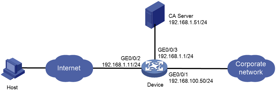
As shown in Figure 1, establish an L2TP tunnel between the PPP user's host and the device. The specific requirements are as follows:
· Use the Windows Server 2003 as the CA server.
· Configure access to the corporate network through the L2TP tunnel.
· Encrypt the L2TP tunnel data through IPsec.
· Establish an IPsec tunnel by using the RSA certificate authentication method.
Analysis
To establish an IPsec tunnel using the certificate authentication method, you must execute the local-identity command to specify the DN in the local certificate as the local ID for the IKE profile.
Software versions used
This configuration example was created and verified on R9141P16 of the MSR2630E-X1 device.
Procedures
Configuring the device
Table 1 Configure IP addresses for interfaces:
# Assign IP address 192.168.100.50 to interface GigabitEthernet 0/0/1.
<Device> system-view
[Device] interface gigabitethernet 0/0/1
[Device-GigabitEthernet0/0/1] ip address 192.168.100.50 24
[Device-GigabitEthernet0/0/1] quit
# Assign IP address 102.168.1.11 to interface GigabitEthernet 0/0/2.
[Device] interface gigabitethernet 0/0/2
[Device-GigabitEthernet0/0/2] ip address 102.168.1.11 24
[Device-GigabitEthernet0/0/2] quit
# Assign IP address 192.168.1.1 to interface GigabitEthernet 0/0/3.
[Device] interface gigabitethernet 0/0/3
[Device-GigabitEthernet0/0/3] ip address 192.168.1.1 24
[Device-GigabitEthernet0/0/3] quit
Table 2 Configure L2TP:
# Create a local PPP user with username l2tpuser and password hello.
[Device] local-user l2tpuser class network
[Device-luser-network-l2tpuser] password simple hello
[Device-luser-network-l2tpuser] service-type ppp
[Device-luser-network-l2tpuser] quit
# Configure ISP domain system to perform local authentication for PPP users.
[Device] domain system
[Device-isp-system] authentication ppp local
[Device-isp-system] quit
# Enable L2TP.
[Device] l2tp enable
# Create Virtual-Template 0, and assign IP address 172.16.0.1/24 to the interface.
[Device] interface virtual-template 0
[Device-Virtual-Template0] ip address 172.16.0.1 255.255.255.0
# Specify the PPP authentication mode as PAP.
[Device-Virtual-Template0] ppp authentication-mode pap
# Assign IP address 172.16.0.2 to the PPP user.
[Device-Virtual-Template0] remote address 172.16.0.2
[Device-Virtual-Template0] quit
# Create L2TP group 1 in LNS mode.
[Device] l2tp-group 1 mode lns
# Configure the local tunnel name as lns.
[Device-l2tp1] tunnel name lns
# Disable L2TP tunnel authentication.
[Device-l2tp1] undo tunnel authentication
# Specify Virtual-Template 0 for receiving calls.
[Device-l2tp1] allow l2tp virtual-template 0
[Device-l2tp1] quit
Table 3 Configure PKI certificates
# Configure an entity named security.
[Device] pki entity security
[Device-pki-entity-security] common-name device
[Device-pki-entity-security] quit
# Create a PKI domain.
[Device] pki domain headgate
[Device-pki-domain-headgate] ca identifier LYQ
[Device-pki-domain-headgate] certificate request url http://192.168.1.51/certsrv/mscep/mscep.dll
[Device-pki-domain-headgate] certificate request from ra
[Device-pki-domain-headgate] certificate request entity security
[Device-pki-domain-headgate] undo crl check enable
[Device-pki-domain-headgate] public-key rsa general name abc length 1024
[Device-pki-domain-headgate] quit
# Generate an RSA key pair.
[Device] public-key local create rsa name abc
The range of public key modulus is (512 ~ 2048).
If the key modulus is greater than 512,it will take a few minutes.
Press CTRL+C to abort.
Input the modulus length [default = 1024]:
Generating Keys...
..........................++++++
.++++++
Create the key pair successfully.
# Obtain the CA certificate and save it locally.
[Device] pki retrieve-certificate domain headgate ca
The trusted CA's finger print is:
MD5 fingerprint:8649 7A4B EAD5 42CF 5031 4C99 BFS3 2A99
SHA1 fingerprint:61A9 6034 181E 6502 12FA 5A5F BA12 0EA0 5187 031C
Is the finger print correct?(Y/N):y
Retrieved the certificates successfully.
# Submit a local certificate request.
[Device] pki request-certificate domain headgate
Start to request general certificate ...
Certificate requested successfully.
Table 4 Configure an IPsec tunnel:
# Create an IKE proposal.
[Device] ike proposal 1
[Device-ike-proposal-1] authentication-method rsa-signature
[Device-ike-proposal-1] encryption-algorithm 3des-cbc
[Device-ike-proposal-1] dh group2
[Device-ike-proposal-1] quit
# Create an IPsec transform set.
[Device] ipsec transform-set tran1
[Device-ipsec-transform-set-tran1] esp authentication-algorithm sha1
[Device-ipsec-transform-set-tran1] esp encryption-algorithm 3des
[Device-ipsec-transform-set-tran1] quit
# Create an IKE profile.
[Device] ike profile profile1
[Device-ike-profile-profile1] local-identity dn
[Device-ike-profile-profile1] certificate domain headgate
[Device-ike-profile-profile1] proposal 1
[Device-ike-profile-profile1] match remote certificate device
[Device-ike-profile-profile1] quit
# Configure the local device to obtain the identity information from the local certificate for signature authentication.
[Device]ike signature-identity from-certificate
# Create an IPsec policy template entry. Specify the template name as template1 and set the sequence number to 1.
[Device] ipsec policy-template template1 1
[Device-ipsec-policy-template-template1-1] transform-set tran1
[Device-ipsec-policy-template-template1-1] ike-profile profile1
[Device-ipsec-policy-template-template1-1] quit
# Create an IKE-based IPsec policy entry by using IPsec policy template template1. Specify the policy name as policy1 and set the sequence number to 1.
[Device] ipsec policy policy1 1 isakmp template template1
# Apply IPsec policy policy1 to GigabitEthernet 0/0/2.
[Device] interface gigabitethernet 0/0/2
[Device-GigabitEthernet0/0/2] ipsec apply policy policy1
[Device-GigabitEthernet0/0/2] quit
Configuring the host
Table 5 Request the client's certificate from the certificate server. This example uses the Microsoft Active Directory Certificate Services as the certificate server.
# Log in the Microsoft Active Directory Certificate Services web interface at https://CA_server_IP/certsrv. This example uses http://192.168.1.51/certsrv. Then click Request a certificate.
# On the page that opens, click advanced certificate request.
# Click Create and submit a request to this CA.
# Configure the relevant parameters.
¡ Select Client Authentication Certificate in the Certificate Type field.
¡ In the Key Options area, select Mark keys as exportable.
# In the Web access confirmation dialog box that opens, click Yes.
# Click Install this certificate.
Table 6 Configure the iNode client. This example uses iNode PC 5.2 (E0409).
# Open the L2TP VPN connection window, and click Properties... (Y).
# Enter the LNS server address, enable the IPsec security protocol, and select certificate authentication as the validation method.
# Click Advanced (C) to access the L2TP Settings tab and configure L2TP parameters as follows.
# Click the IPsec Settings tab and configure IPsec parameters as follows.
# Click the IKE Settings tab and configure IKE parameters as follows.
# Click the Route Settings tab and add a route to access the corporate network.
# Click OK to return to the L2TP connection page.
Verifying the configuration
# In the L2TP connection dialog box, enter username l2tpuser and password hello, then click Connect (C).
# In the popup dialog box, select the requested certificate, and then click OK.
# View the L2TP connection success page. You can view connection running information.
# Execute the display ike sa command to view the IKE SA on the device.
<Device> display ike sa
Connection-ID Remote Flag DOI
------------------------------------------------------------------
10 102.168.1.1 RD IPSEC
Flags:
RD--READY RL--REPLACED FD-FADING RK-REKEY
# Execute the display ipsec sa command to view the IPsec SA information on the device.
<Device> display ipsec sa
-------------------------------
Interface: GigabitEthernet0/0/2
-------------------------------
-----------------------------
IPsec policy: policy1
Sequence number: 1
Mode: template
-----------------------------
Tunnel id: 0
Encapsulation mode: tunnel
Perfect forward secrecy:
Path MTU: 1443
Tunnel:
local address: 102.168.1.11
remote address: 102.168.1.1
Flow:
sour addr: 102.168.1.11/255.255.255.255 port: 1701 protocol: udp
dest addr: 102.168.1.1/255.255.255.255 port: 0 protocol: udp
[Inbound ESP SAs]
SPI: 2187699078 (0x8265a386)
Transform set: ESP-ENCRYPT-3DES-CBC ESP-AUTH-SHA1
SA duration (kilobytes/sec): 1843200/3600
SA remaining duration (kilobytes/sec): 1843197/3294
Max received sequence-number: 51
Anti-replay check enable: Y
Anti-replay window size: 64
UDP encapsulation used for NAT traversal: N
Status: Active
[Outbound ESP SAs]
SPI: 3433374591 (0xcca5237f)
Transform set: ESP-ENCRYPT-3DES-CBC ESP-AUTH-SHA1
SA duration (kilobytes/sec): 1843200/3600
SA remaining duration (kilobytes/sec): 1843197/3294
Max sent sequence-number: 52
UDP encapsulation used for NAT traversal: N
Status: Active
Configuration files
#
interface Virtual-Template0
ppp authentication-mode pap
remote address 172.16.0.2
ip address 172.16.0.1 255.255.255.0
#
interface GigabitEthernet0/0/1
ip address 192.168.100.50 255.255.255.0
#
interface GigabitEthernet0/0/2
ip address 102.168.1.11 255.255.255.0
ipsec apply policy policy1
#
interface GigabitEthernet0/0/3
ip address 192.168.1.1 255.255.255.0
#
domain system
authentication ppp local
#
local-user l2tpuser class network
password cipher $c$3$nl46fURLtkCkcbdnB6irTXma+E6u0c+h
service-type ppp
authorization-attribute user-role network-operator
#
pki domain headgate
ca identifier LYQ
certificate request url http://192.168.1.51/certsrv/mscep/mscep.dll
certificate request from ra
certificate request entity security
public-key rsa general name abc
undo crl check enable
#
pki entity security
common-name device
#
ipsec transform-set tran1
esp encryption-algorithm 3des-cbc
esp authentication-algorithm sha1
#
ipsec policy-template template1 1
transform-set tran1
ike-profile profile1
#
ipsec policy policy1 1 isakmp template template1
#
l2tp-group 1 mode lns
allow l2tp virtual-template 0
undo tunnel authentication
tunnel name lns
#
l2tp enable
#
ike signature-identity from-certificate
#
ike profile profile1
certificate domain headgate
local-identity dn
match remote certificate device
proposal 1
#
ike proposal 1
authentication-method rsa-signature
encryption-algorithm 3des-cbc
dh group2
#
Example: Configuring IPsec over GRE
Network configuration
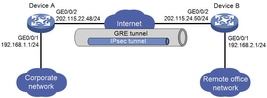
As shown in Figure 2, the enterprise remote office network accesses the headquarters through IPsec VPN. Configure the network to transmit IPsec encrypted data between the corporate network and the remote office network through a GRE tunnel.
Analysis
To process data with IPsec first and then encapsulate it with GRE, you must configure an ACL to identify the packets to be protected and apply the IPsec policy to the GRE tunnel interface on each device.
To encapsulate the data transmitted between networks with IPsec first and then with GRE, you must configure the remote IP address of the IPsec tunnel as the interface address of the GRE tunnel on each device.
Software versions used
This configuration example was created and verified on R9141P16 of the MSR2630E-X1 device.
Procedures
Configuring Device A
Table 7 Configure IP addresses for interfaces:
# Assign IP address 192.168.1.1 to interface GigabitEthernet 0/0/1.
<DeviceA> system-view
[DeviceA] interface gigabitethernet 1/0/1
[DeviceA-GigabitEthernet0/0/1] ip address 192.168.1.1 255.255.255.0
[DeviceA-GigabitEthernet0/0/1] tcp mss 1350
[DeviceA-GigabitEthernet0/0/1] quit
# Assign IP address 202.115.22.48 to interface GigabitEthernet 0/0/2.
[DeviceA] interface gigabitethernet 0/0/2
[DeviceA-GigabitEthernet0/0/2] ip address 202.115.22.48 255.255.255.0
[DeviceA-GigabitEthernet0/0/2] quit
Table 8 Configure the GRE tunnel:
# Create tunnel interface Tunnel 0, and specify the tunnel mode as GRE/IPv4.
[DeviceA] interface tunnel 0 mode gre
# Assign an IP address to interface Tunnel 0.
[DeviceA-Tunnel0] ip address 10.1.1.1 255.255.255.0
# Configure the source address of interface Tunnel 0 (as the IP address of GigabitEthernet 0/0/2 on Device A).
[DeviceA-Tunnel0] source 202.115.22.48
# Configure the destination address of interface Tunnel 0 (as the IP address of GigabitEthernet 0/0/2 on Device B).
[DeviceA-Tunnel0] destination 202.115.24.50
[DeviceA-Tunnel0] quit
# Configure a static route from Device A through interface Tunnel 0 to the remote office network.
[DeviceA] ip route-static 192.168.2.1 255.255.255.0 tunnel 0
Table 9 Configure the IPsec VPN:
# Create an IKE keychain.
[DeviceA] ike keychain keychain1
[DeviceA-ike-keychain-keychain1] pre-shared-key address 10.1.1.2 255.255.255.0 key simple 123
[DeviceA-ike-keychain-keychain1] quit
# Specify ACL 3000 to identify the traffic to be protected.
[DeviceA] acl number 3000
[DeviceA-acl-adv-3000] rule 0 permit ip source 192.168.1.0 0.0.0.255 destination 192.168.2.0 0.0.0.255
[DeviceA-acl-adv-3000] quit
# Create an IPsec transform set.
[DeviceA] ipsec transform-set tran1
[DeviceA-ipsec-transform-set-tran1] esp encryption-algorithm des
[DeviceA-ipsec-transform-set-tran1] esp authentication-algorithm sha1
[DeviceA-ipsec-transform-set-tran1] quit
# Create an IKE-based IPsec policy entry. Specify the policy name as policy1 and set the sequence number to 1.
[DeviceA] ipsec policy policy1 1 isakmp
[DeviceA-ipsec-policy-isakmp-policy1-1] security acl 3000
[DeviceA-ipsec-policy-isakmp-policy1-1] remote-address 10.1.1.2
[DeviceA-ipsec-policy-isakmp-policy1-1] transform-set tran1
[DeviceA-ipsec-policy-isakmp-policy1-1] quit
# Apply IPsec policy policy1 to interface Tunnel 0.
[DeviceA] interface tunnel 0
[DeviceA-Tunnel0] ipsec apply policy policy1
[DeviceA-Tunnel0] quit
Configuring Device B
Table 10 Configure IP addresses for interfaces:
# Assign IP address 192.168.2.1 to interface GigabitEthernet 0/0/1.
<DeviceB> system-view
[DeviceB] interface gigabitethernet 1/0/1
[DeviceB-GigabitEthernet0/0/1] ip address 192.168.2.1 255.255.255.0
[DeviceB-GigabitEthernet0/0/1] tcp mss 1350
[DeviceB-GigabitEthernet0/0/1] quit
# Assign IP address 202.115.24.50 to interface GigabitEthernet 0/0/2.
[DeviceB] interface gigabitethernet 0/0/2
[DeviceB-GigabitEthernet0/0/2] ip address 202.115.24.50 255.255.255.0
[DeviceB-GigabitEthernet0/0/2] quit
Table 11 Configure the GRE tunnel:
# Create tunnel interface Tunnel 0, and specify the tunnel mode as GRE/IPv4.
[DeviceB] interface tunnel 0 mode gre
# Assign an IP address to Tunnel 0.
[DeviceB-Tunnel0] ip address 10.1.1.2 255.255.255.0
# Configure the source address of interface Tunnel 0 (as the IP address of GigabitEthernet 0/0/2 on Device B).
[DeviceB-Tunnel0] source 202.115.24.50
# Configure the destination address of interface Tunnel 0 (as the IP address of GigabitEthernet 0/0/2 on Device A).
[DeviceB-Tunnel0] destination 202.115.22.48
[DeviceB-Tunnel0] quit
# Configure a static route from Device B through Tunnel 0 to the corporate network.
[DeviceB] ip route-static 192.168.1.1 255.255.255.0 tunnel 0
Table 12 Configure the IPsec VPN:
# Create an IKE keychain.
[DeviceB] ike keychain keychain1
[DeviceB-ike-keychain-keychain1] pre-shared-key address 10.1.1.1 255.255.255.0 key simple 123
[DeviceB-ike-keychain-keychain1] quit
# Specify ACL 3000 to identify the traffic to be protected.
[DeviceB] acl number 3000
[DeviceB-acl-adv-3000] rule 0 permit ip source 192.168.2.0 0.0.0.255 destination 192.168.1.0 0.0.0.255
[DeviceB-acl-adv-3000] quit
# Create an IPsec transform set.
[DeviceB] ipsec transform-set tran1
[DeviceB-ipsec-transform-set-tran1] esp encryption-algorithm des
[DeviceB-ipsec-transform-set-tran1] esp authentication-algorithm sha1
[DeviceB-ipsec-transform-set-tran1] quit
# Create an IKE-based IPsec policy entry. Specify the policy name as policy1 and set the sequence number to 1.
[DeviceB] ipsec policy policy1 1 isakmp
[DeviceB-ipsec-policy-isakmp-policy1-1] security acl 3000
[DeviceB-ipsec-policy-isakmp-policy1-1] remote-address 10.1.1.1
[DeviceB-ipsec-policy-isakmp-policy1-1] transform-set tran1
[DeviceB-ipsec-policy-isakmp-policy1-1] quit
# Apply IPsec policy policy1 to Tunnel 0.
[DeviceB] interface tunnel 0
[DeviceB-Tunnel0] ipsec apply policy policy1
[DeviceB-Tunnel0] quit
Verifying the configuration
# Initiate a connection from the host at 192.168.1.2 in the corporate network to the host at 192.168.2.2 in the remote office network to trigger IKE negotiation. Verify that you can successfully ping 192.168.2.2 from 192.168.1.2 after the IPsec tunnel is successfully established.
C:\Users\corporatenetwork> ping 192.168.2.2
Pinging 192.168.2.2 with 32 bytes of data:
Request timed out.
Reply from 192.168.2.2: bytes=32 time=2ms TTL=254
Reply from 192.168.2.2: bytes=32 time=2ms TTL=254
Reply from 192.168.2.2: bytes=32 time=1ms TTL=254
Ping statistics for 192.168.2.2:
Packets: Sent = 4, Received = 3, Lost = 1 (25% loss),
Approximate round trip times in milli-seconds:
Minimum = 1ms, Maximum = 2ms, Average = 1ms
# Execute the display ike sa command to view the IKE SA on Device A.
<DeviceA> display ike sa
Connection-ID Remote Flag DOI
------------------------------------------------------------------
1 10.1.1.2 RD IPSEC
Flags:
RD--READY RL--REPLACED FD-FADING RK-REKEY
# Execute the display ipsec sa command to view the IPsec SA information on Device A.
<DeviceA> display ipsec sa
-------------------------------
Interface: Tunnel0
-------------------------------
-----------------------------
IPsec policy: policy1
Sequence number: 1
Mode: isakmp
-----------------------------
Tunnel id: 0
Encapsulation mode: tunnel
Perfect forward secrecy:
Path MTU: 1419
Tunnel:
local address: 10.1.1.1
remote address: 10.1.1.2
Flow:
sour addr: 192.168.1.1/255.255.255.255 port: 0 protocol: ip
dest addr: 192.168.2.1/255.255.255.255 port: 0 protocol: ip
[Inbound ESP SAs]
SPI: 3128557135 (0xba79fe4f)
Transform set: ESP-ENCRYPT-DES-CBC ESP-AUTH-SHA1
SA duration (kilobytes/sec): 1843200/3600
SA remaining duration (kilobytes/sec): 1843199/3550
Max received sequence-number: 3
Anti-replay check enable: Y
Anti-replay window size: 64
UDP encapsulation used for NAT traversal: N
Status: Active
[Outbound ESP SAs]
SPI: 2643166978 (0x9d8b8702)
Transform set: ESP-ENCRYPT-DES-CBC ESP-AUTH-SHA1
SA duration (kilobytes/sec): 1843200/3600
SA remaining duration (kilobytes/sec): 1843199/3550
Max sent sequence-number: 3
UDP encapsulation used for NAT traversal: N
Status: Active
# Execute the display interface tunnel 0 command to view information about the traffic transmitted through the GRE tunnel on Device A.
<DeviceA> display interface tunnel 0
Tunnel0
Current state: UP
Line protocol state: UP
Description: Tunnel0 Interface
Bandwidth: 64kbps
Maximum Transmit Unit: 1476
Internet Address is 10.1.1.1/24 Primary
Tunnel source 202.115.22.48, destination 202.115.24.50
Tunnel keepalive disabled
Tunnel TTL 255
Tunnel protocol/transport GRE/IP
GRE key disabled
Checksumming of GRE packets disabled
Output queue - Urgent queuing: Size/Length/Discards 0/100/0
Output queue - Protocol queuing: Size/Length/Discards 0/500/0
Output queue - FIFO queuing: Size/Length/Discards 0/75/0
Last clearing of counters: Never
Last 300 seconds input rate: 0 bytes/sec, 0 bits/sec, 0 packets/sec
Last 300 seconds output rate: 0 bytes/sec, 0 bits/sec, 0 packets/sec
Input: 40 packets, 3300 bytes, 0 drops
Output: 41 packets, 3464 bytes, 0 drops
# Initiate a connection from a host in the remote office network to a host in the corporate network to verify the connectivity. (Details not shown.)
Configuration files
· Device A:
#
interface GigabitEthernet0/0/1
ip address 192.168.1.1 255.255.255.0
tcp mss 1350
#
interface GigabitEthernet0/0/2
ip address 202.115.22.48 255.255.255.0
#
interface Tunnel0 mode gre
ip address 10.1.1.1 255.255.255.0
source 202.115.22.48
destination 202.115.24.50
ipsec apply policy policy1
#
ip route-static 192.168.2.1 24 Tunnel0
#
acl number 3000
rule 0 permit ip source 192.168.1.0 0.0.0.255 destination 192.168.2.0 0.0.0.255
#
ipsec transform-set tran1
esp encryption-algorithm des-cbc
esp authentication-algorithm sha1
#
ipsec policy policy1 1 isakmp
transform-set tran1
security acl 3000
remote-address 10.1.1.2
#
ike keychain keychain1
pre-shared-key address 10.1.1.2 255.255.255.0 key cipher $c$3$n6jdlYtuR+K6mijQ8qp4hMMjV/iteA==
#
· Device B:
#
interface GigabitEthernet0/0/1
ip address 192.168.2.1 255.255.255.0
tcp mss 1350
#
interface GigabitEthernet0/0/2
ip address 202.115.24.50 255.255.255.0
#
interface Tunnel0 mode gre
ip address 10.1.1.2 255.255.255.0
source 202.115.24.50
destination 202.115.22.48
ipsec apply policy policy1
#
ip route-static 192.168.1.1 24 Tunnel0
#
acl number 3000
rule 0 permit ip source 192.168.2.0 0.0.0.255 destination 192.168.1.0 0.0.0.255
#
ipsec transform-set tran1
esp encryption-algorithm des-cbc
esp authentication-algorithm sha1
#
ipsec policy policy1 1 isakmp
transform-set tran1
security acl 3000
remote-address 10.1.1.1
#
ike keychain keychain1
pre-shared-key address 10.1.1.1 255.255.255.0 key cipher $c$3$n6jdlYtuR+K6mijQ8qp4hMMjV/iteA==
#
Example: Configuring GRE over IPsec
Network configuration
As shown in Figure 3, the enterprise remote office network transmits data to the headquarters through a GRE tunnel. Configure the network to encrypt the data passing through the GRE tunnel using IPsec.

Analysis
To encrypt the data encapsulated by GRE with IPsec, you must apply the IPsec policy on the physical interface connected to the peer device, and configure the source and destination addresses for the ACL as the physical interface address on each device.
To have IPsec protect the entire GRE tunnel, make sure the physical interface applying the IPsec policy and the GRE tunnel source or destination interface are the same interface.
Software versions used
This configuration example was created and verified on R9141P16 of the MSR2630E-X1 device.
Procedures
Configuring Device A
Table 1 Configure IP addresses for interfaces:
# Assign IP address 192.168.1.1 to interface GigabitEthernet 0/0/1.
<DeviceA> system-view
[DeviceA] interface gigabitethernet 1/0/1
[DeviceA-GigabitEthernet0/0/1] ip address 192.168.1.1 255.255.255.0
[DeviceA-GigabitEthernet0/0/1] quit
# Assign IP address 202.115.22.48 to interface GigabitEthernet 0/0/2.
[DeviceA] interface gigabitethernet 0/0/2
[DeviceA-GigabitEthernet0/0/2] ip address 202.115.22.48 255.255.255.0
[DeviceA-GigabitEthernet0/0/2] quit
Table 2 Configure the GRE tunnel:
# Create tunnel interface Tunnel 0, and specify the tunnel mode as GRE/IPv4.
[DeviceA] interface tunnel 0 mode gre
# Assign an IP address to interface Tunnel 0.
[DeviceA-Tunnel0] ip address 10.1.1.1 255.255.255.0
# Configure the source address of interface Tunnel 0 (as the IP address of GigabitEthernet 0/0/2 on Device A).
[DeviceA-Tunnel0] source 202.115.22.48
# Configure the destination address of interface Tunnel 0 (as the IP address of GigabitEthernet 0/0/2 on Device B).
[DeviceA-Tunnel0] destination 202.115.24.50
[DeviceA-Tunnel0] quit
# Configure a static route from Device A through interface Tunnel 0 to the remote office network.
[DeviceA] ip route-static 192.168.2.1 255.255.255.0 tunnel 0
Table 3 Configure the IPsec VPN:
# Create an IKE keychain.
[DeviceA] ike keychain keychain1
[DeviceA-ike-keychain-keychain1] pre-shared-key address 202.115.24.50 255.255.255.0 key simple 123
[DeviceA-ike-keychain-keychain1] quit
# Specify ACL 3000 to identify the traffic to be protected.
[DeviceA] acl number 3000
[DeviceA-acl-adv-3000] rule 0 permit gre source 202.115.22.48 0 destination 202.115.24.50 0
[DeviceA-acl-adv-3000] quit
# Create an IPsec transform set.
[DeviceA] ipsec transform-set tran1
[DeviceA-ipsec-transform-set-tran1] esp encryption-algorithm des
[DeviceA-ipsec-transform-set-tran1] esp authentication-algorithm sha1
[DeviceA-ipsec-transform-set-tran1] quit
# Create an IKE-based IPsec policy entry. Specify the policy name as policy1 and set the sequence number to 1.
[DeviceA] ipsec policy policy1 1 isakmp
[DeviceA-ipsec-policy-isakmp-policy1-1] security acl 3000
[DeviceA-ipsec-policy-isakmp-policy1-1] remote-address 202.115.24.50
[DeviceA-ipsec-policy-isakmp-policy1-1] transform-set tran1
[DeviceA-ipsec-policy-isakmp-policy1-1] quit
# Apply IPsec policy policy1 to GigabitEthernet 0/0/2.
[DeviceA] interface gigabitethernet 0/0/2
[DeviceA-GigabitEthernet0/0/2] ipsec apply policy policy1
[DeviceA-GigabitEthernet0/0/2] quit
Configuring Device B
Table 1 Configure IP addresses for interfaces:
# Assign IP address192.168.2.1 to interface GigabitEthernet 0/0/1.
<DeviceB> system-view
[DeviceB] interface gigabitethernet 1/0/1
[DeviceB-GigabitEthernet0/0/1] ip address 192.168.2.1 255.255.255.0
[DeviceB-GigabitEthernet0/0/1] quit
# Assign IP address 202.115.24.50 to interface GigabitEthernet 0/0/2.
[DeviceB] interface gigabitethernet 0/0/2
[DeviceB-GigabitEthernet0/0/2] ip address 202.115.24.50 255.255.255.0
[DeviceB-GigabitEthernet0/0/2] quit
Table 2 Configure the GRE tunnel:
# Create tunnel interface Tunnel 0, and specify the tunnel mode as GRE/IPv4.
[DeviceB] interface tunnel 0 mode gre
# Assign an IP address to Tunnel 0.
[DeviceB-Tunnel0] ip address 10.1.1.2 255.255.255.0
# Configure the source address of interface Tunnel 0 (as the IP address of GigabitEthernet 0/0/2 on Device B).
[DeviceB-Tunnel0] source 202.115.24.50
# Configure the destination address of interface Tunnel 0 (as the IP address of GigabitEthernet 0/0/2 on Device A).
[DeviceB-Tunnel0] destination 202.115.22.48
[DeviceB-Tunnel0] quit
# Configure a static route from Device B through interface Tunnel 0 to the corporate network.
[DeviceB] ip route-static 192.168.1.1 255.255.255.0 tunnel 0
Table 3 Configure the IPsec VPN:
# Create an IKE keychain.
[DeviceB] ike keychain keychain1
[DeviceB-ike-keychain-keychain1] pre-shared-key address 202.115.22.48 255.255.255.0 key simple 123
[DeviceB-ike-keychain-keychain1] quit
# Specify ACL 3000 to identify the traffic to be protected.
[DeviceB] acl number 3000
[DeviceB-acl-adv-3000] rule 0 permit gre source 202.115.24.50 0 destination 202.115.22.48 0
[DeviceB-acl-adv-3000] quit
# Create an IPsec transform set.
[DeviceB] ipsec transform-set tran1
[DeviceB-ipsec-transform-set-tran1] esp encryption-algorithm des
[DeviceB-ipsec-transform-set-tran1] esp authentication-algorithm sha1
[DeviceB-ipsec-transform-set-tran1] quit
# Create an IKE-based IPsec policy entry. Specify the policy name as policy1 and set the sequence number to 1.
[DeviceB] ipsec policy policy1 1 isakmp
[DeviceB-ipsec-policy-isakmp-policy1-1] security acl 3000
[DeviceB-ipsec-policy-isakmp-policy1-1] remote-address 202.115.22.48
[DeviceB-ipsec-policy-isakmp-policy1-1] transform-set tran1
[DeviceB-ipsec-policy-isakmp-policy1-1] quit
# Apply IPSec policy policy1 to GigabitEthernet 0/0/2.
[DeviceB] interface gigabitethernet 0/0/2
[DeviceB-GigabitEthernet0/0/2] ipsec apply policy policy1
[DeviceB-GigabitEthernet0/0/2] quit
Verifying the configuration
# Initiate a connection from the host at 192.168.1.2 in the corporate network to the host at 192.168.2.2 in the remote office network to trigger IKE negotiation. Verify that you can successfully ping 192.168.2.2 from 192.168.1.2 after the IPsec tunnel is successfully established.
C:\Users\corporatenetwork> ping 192.168.2.2
Pinging 192.168.2.2 with 32 bytes of data:
Request timed out.
Reply from 192.168.2.2: bytes=32 time=2ms TTL=254
Reply from 192.168.2.2: bytes=32 time=2ms TTL=254
Reply from 192.168.2.2: bytes=32 time=1ms TTL=254
Ping statistics for 192.168.2.2:
Packets: Sent = 4, Received = 3, Lost = 1 (25% loss),
Approximate round trip times in milli-seconds:
Minimum = 1ms, Maximum = 2ms, Average = 1ms
# Execute the display ike sa command to view the IKE SA on Device A.
<DeviceA> display ike sa
Connection-ID Remote Flag DOI
------------------------------------------------------------------
2 202.115.24.50 RD IPSEC
Flags:
RD--READY RL--REPLACED FD-FADING RK-REKEY
# Execute the display ipsec sa command to view the IPsec SA information on Device A.
<DeviceA> display ipsec sa
-------------------------------
Interface: GigabitEthernet0/0/2
-------------------------------
-----------------------------
IPsec policy: policy1
Sequence number: 1
Mode: isakmp
-----------------------------
Tunnel id: 0
Encapsulation mode: tunnel
Perfect forward secrecy:
Path MTU: 1443
Tunnel:
local address: 202.115.22.48
remote address: 202.115.24.50
Flow:
sour addr: 202.115.22.48/255.255.255.255 port: 0 protocol: gre
dest addr: 202.115.24.50/255.255.255.255 port: 0 protocol: gre
[Inbound ESP SAs]
SPI: 2130348402 (0x7efa8972)
Transform set: ESP-ENCRYPT-DES-CBC ESP-AUTH-SHA1
SA duration (kilobytes/sec): 1843200/3600
SA remaining duration (kilobytes/sec): 1843199/3573
Max received sequence-number: 3
Anti-replay check enable: Y
Anti-replay window size: 64
UDP encapsulation used for NAT traversal: N
Status: Active
[Outbound ESP SAs]
SPI: 2811839266 (0xa7994322)
Transform set: ESP-ENCRYPT-DES-CBC ESP-AUTH-SHA1
SA duration (kilobytes/sec): 1843200/3600
SA remaining duration (kilobytes/sec): 1843199/3573
Max sent sequence-number: 3
UDP encapsulation used for NAT traversal: N
Status: Active
# Execute the display interface tunnel 0 command to view information about the traffic transmitted through the GRE tunnel on Device A.
<DeviceA> display interface tunnel 0
Tunnel0
Current state: UP
Line protocol state: UP
Description: Tunnel0 Interface
Bandwidth: 64kbps
Maximum Transmit Unit: 1476
Internet Address is 10.1.1.1/24 Primary
Tunnel source 202.115.22.48, destination 202.115.24.50
Tunnel keepalive disabled
Tunnel TTL 255
Tunnel protocol/transport GRE/IP
GRE key disabled
Checksumming of GRE packets disabled
Output queue - Urgent queuing: Size/Length/Discards 0/100/0
Output queue - Protocol queuing: Size/Length/Discards 0/500/0
Output queue - FIFO queuing: Size/Length/Discards 0/75/0
Last clearing of counters: Never
Last 300 seconds input rate: 0 bytes/sec, 0 bits/sec, 0 packets/sec
Last 300 seconds output rate: 0 bytes/sec, 0 bits/sec, 0 packets/sec
Input: 43 packets, 3480 bytes, 0 drops
Output: 45 packets, 3740 bytes, 2 drops
# Initiate a connection from a host in the remote office network to a host in the corporate network to verify the connectivity. (Details not shown.)
Configuration files
· Device A:
#
interface GigabitEthernet0/0/1
ip address 192.168.1.1 255.255.255.0
#
interface GigabitEthernet0/0/2
ip address 202.115.22.48 255.255.255.0
ipsec apply policy policy1
#
interface Tunnel0 mode gre
ip address 10.1.1.1 255.255.255.0
source 202.115.22.48
destination 202.115.24.50
#
ip route-static 192.168.2.1 24 Tunnel0
#
acl number 3000
rule 0 permit gre source 202.115.22.48 0 destination 202.115.24.50 0
#
ipsec transform-set tran1
esp encryption-algorithm des-cbc
esp authentication-algorithm sha1
#
ipsec policy policy1 1 isakmp
transform-set tran1
security acl 3000
remote-address 202.115.24.50
#
ike keychain keychain1
pre-shared-key address 202.115.24.50 255.255.255.0 key cipher $c$3$n6jdlYtuR+K6mijQ8
qp4hMMjV/iteA==
#
· Device B:
#
interface GigabitEthernet0/0/1
ip address 192.168.2.1 255.255.255.0
#
interface GigabitEthernet0/0/2
ip address 202.115.24.50 255.255.255.0
ipsec apply policy policy1
#
interface Tunnel0 mode gre
ip address 10.1.1.2 255.255.255.0
source 202.115.24.50
destination 202.115.22.48
#
ip route-static 192.168.1.1 24 Tunnel0
#
acl number 3000
rule 0 permit gre source 202.115.24.50 0 destination 202.115.22.48 0
#
ipsec transform-set tran1
esp encryption-algorithm des-cbc
esp authentication-algorithm sha1
#
ipsec policy policy1 1 isakmp
transform-set tran1
security acl 3000
remote-address 202.115.22.48
#
ike keychain keychain1
pre-shared-key address 202.115.22.48 255.255.255.0 key cipher $c$3$n6jdlYtuR+K6mijQ8
qp4hMMjV/iteA==
#
Example: Configuring dual IPsec tunnels operating in backup mode
Network configuration
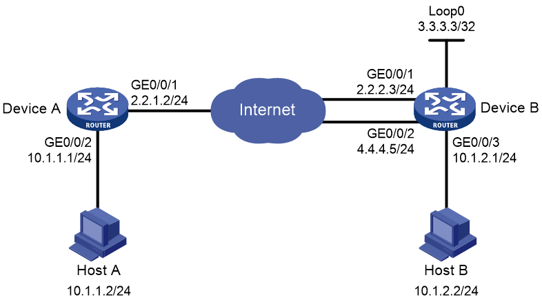
As shown in Figure 4, configure two IPsec tunnels operating in backup mode between Device A and Device B to secure the communication between subnet 10.1.1.0/24 and subnet 10.1.2.0/24.
· Configure the two tunnels to use the security protocol ESP, the encryption algorithm DES, and the authentication algorithm SHA1-HMAC-96. Use IKE for IPsec SA negotiation.
· Configure a shared source interface policy on Device B to achieve smooth traffic switchover between the two interfaces.
Software versions used
This configuration example was created and verified on R9141P16 of the MSR2630E-X1 device.
Procedures
Configuring Device A
Table 1 Configure IP addresses for interfaces:
# Assign IP address 2.2.1.2 to interface GigabitEthernet 0/0/1.
<DeviceA> system-view
[DeviceA] interface gigabitethernet 1/0/1
[DeviceA-GigabitEthernet0/0/1] ip address 2.2.1.2 255.255.255.0
[DeviceA-GigabitEthernet0/0/1] quit
# Assign IP address 10.1.1.1 to interface GigabitEthernet 0/0/2.
[DeviceA] interface gigabitethernet 0/0/2
[DeviceA-GigabitEthernet0/0/2] ip address 10.1.1.1 255.255.255.0
[DeviceA-GigabitEthernet0/0/2] quit
# Configure a static route to subnet 10.1.2.0.
[DeviceA] ip route-static 10.1.2.0 255.255.255.0 2.2.2.3
[DeviceA] ip route-static 10.1.2.0 255.255.255.0 4.4.4.5
# Configure a static route to the Loopback0 interface on Device B.
[DeviceA] ip route-static 3.3.3.3 255.255.255.255 2.2.2.3
[DeviceA] ip route-static 3.3.3.3 255.255.255.255 4.4.4.5
Table 2 Configure the IPsec VPN:
# Create an IKE keychain.
[DeviceA] ike keychain keychain1
[DeviceA-ike-keychain-keychain1] pre-shared-key address 3.3.3.3 255.255.255.255 key simple 123
[DeviceA-ike-keychain-keychain1] quit
# Specify ACL 3000 to identify the traffic to be protected.
[DeviceA] acl number 3000
[DeviceA-acl-adv-3000] rule 0 permit ip source 10.1.1.0 0.0.0.255 destination 10.1.2.0 0.0.0.255
[DeviceA-acl-adv-3000] quit
# Create an IPsec transform set.
[DeviceA] ipsec transform-set tran1
[DeviceA-ipsec-transform-set-tran1] esp encryption-algorithm des
[DeviceA-ipsec-transform-set-tran1] esp authentication-algorithm sha1
[DeviceA-ipsec-transform-set-tran1] quit
# Create an IKE-based IPsec policy entry. Specify the policy name as policy1 and set the sequence number to 1.
[DeviceA] ipsec policy policy1 1 isakmp
[DeviceA-ipsec-policy-isakmp-policy1-1] security acl 3000
[DeviceA-ipsec-policy-isakmp-policy1-1] remote-address 3.3.3.3
[DeviceA-ipsec-policy-isakmp-policy1-1] transform-set tran1
[DeviceA-ipsec-policy-isakmp-policy1-1] quit
# Apply IPsec policy policy1 to GigabitEthernet 0/0/1.
[DeviceA] interface gigabitethernet 1/0/1
[DeviceA-GigabitEthernet0/0/1] ipsec apply policy policy1
[DeviceA-GigabitEthernet0/0/1] quit
Configuring Device B
Table 1 Configure IP addresses for interfaces:
# Assign IP address 2.2.2.3 to interface GigabitEthernet 0/0/1.
<DeviceB> system-view
[DeviceB] interface gigabitethernet 1/0/1
[DeviceB-GigabitEthernet0/0/1] ip address 2.2.2.3 255.255.255.0
[DeviceB-GigabitEthernet0/0/1] quit
# Assign IP address 4.4.4.5 to interface GigabitEthernet 0/0/2.
[DeviceB] interface gigabitethernet 0/0/2
[DeviceB-GigabitEthernet0/0/2] ip address 4.4.4.5 255.255.255.0
[DeviceB-GigabitEthernet0/0/2] quit
# Assign IP address 10.1.2.1 to interface GigabitEthernet 0/0/3.
[DeviceB] interface gigabitethernet 0/0/3
[DeviceB-GigabitEthernet0/0/3] ip address 10.1.2.1 255.255.255.0
[DeviceB-GigabitEthernet0/0/3] quit
# Assign an IP address to Loopback 0.
[DeviceB] interface loopback 0
[DeviceB-LoopBack0] ip address 3.3.3.3 255.255.255.0
[DeviceB-LoopBack0] quit
# Configure a static route to subnet 10.1.1.0.
[DeviceB] ip route-static 10.1.1.0 255.255.255.0 gigabitethernet 1/0/1 2.2.1.2
[DeviceB] ip route-static 10.1.1.0 255.255.255.0 gigabitethernet 0/0/2 2.2.1.2
Table 2 Configure the IPsec VPN:
# Create an IKE keychain.
[DeviceB] ike keychain keychain1
[DeviceB-ike-keychain-keychain1] pre-shared-key address 2.2.1.2 255.255.255.0 key simple 123
[DeviceB-ike-keychain-keychain1] quit
# Specify ACL 3000 to identify the traffic to be protected.
[DeviceB] acl number 3000
[DeviceB-acl-adv-3000] rule 0 permit ip source 10.1.2.0 0.0.0.255 destination 10.1.1.0 0.0.0.255
[DeviceB-acl-adv-3000] quit
# Create an IPsec transform set.
[DeviceB] ipsec transform-set tran1
[DeviceB-ipsec-transform-set-tran1] esp encryption-algorithm des
[DeviceB-ipsec-transform-set-tran1] esp authentication-algorithm sha1
[DeviceB-ipsec-transform-set-tran1] quit
# Create an IKE-based IPsec policy entry. Specify the policy name as policy1 and set the sequence number to 1.
[DeviceB] ipsec policy policy1 1 isakmp
[DeviceB-ipsec-policy-isakmp-policy1-1] security acl 3000
[DeviceB-ipsec-policy-isakmp-policy1-1] remote-address 2.2.1.2
[DeviceB-ipsec-policy-isakmp-policy1-1] transform-set tran1
[Device-ipsec-policy-isakmp-policy1-1] quit
# Apply IPsec policy policy1 to GigabitEthernet 0/0/1.
[DeviceB] interface gigabitethernet 1/0/1
[DeviceB-GigabitEthernet0/0/1] ipsec apply policy policy1
[DeviceB-GigabitEthernet0/0/1] quit
# Apply IPsec policy policy1 to GigabitEthernet 0/0/2.
[DeviceB] interface gigabitethernet 0/0/2
[DeviceB-GigabitEthernet0/0/2] ipsec apply policy policy1
[DeviceB-GigabitEthernet0/0/2] quit
# Configure IPsec policy policy1 as a shared source interface policy, and bind it to source interface Loopback 0.
[DeviceB] ipsec policy policy1 local-address loopback 0
Verifying the configuration
# Initiate a connection from Host A to Host B to trigger IPsec negotiation. Verify that you can successfully ping Host B after the IPsec tunnel is established.
C:\Users\hosta> ping 10.1.2.2
Pinging 10.1.2.2 with 32 bytes of data:
Request timed out.
Reply from 10.1.2.2: bytes=32 time=3ms TTL=126
Reply from 10.1.2.2: bytes=32 time=1ms TTL=126
Reply from 10.1.2.2: bytes=32 time=5ms TTL=126
Ping statistics for 10.1.2.2:
Packets: Sent = 4, Received = 3, Lost = 1 (25% loss),
Approximate round trip times in milli-seconds:
Minimum = 1ms, Maximum = 5ms, Average = 3ms
# Execute the display ike sa command to view the IKE SA on Device A.
[DeviceA] display ike sa
Connection-ID Remote Flag DOI
------------------------------------------------------------------
9 3.3.3.3 RD IPSEC
Flags:
RD--READY RL--REPLACED FD-FADING RK-REKEY
# Execute the display ipsec sa command to view the IPsec SA information on Device A.
[DeviceA] display ipsec sa
-------------------------------
Interface: GigabitEthernet0/0/1
-------------------------------
-----------------------------
IPsec policy: policy1
Sequence number: 1
Mode: isakmp
-----------------------------
Tunnel id: 0
Encapsulation mode: tunnel
Perfect forward secrecy:
Path MTU: 1443
Tunnel:
local address: 2.2.1.2
remote address: 3.3.3.3
Flow:
sour addr: 10.1.1.0/255.255.255.0 port: 0 protocol: ip
dest addr: 10.1.2.0/255.255.255.0 port: 0 protocol: ip
[Inbound ESP SAs]
SPI: 1851852454 (0x6e6106a6)
Transform set: ESP-ENCRYPT-DES-CBC ESP-AUTH-SHA1
SA duration (kilobytes/sec): 1843200/3600
SA remaining duration (kilobytes/sec): 1843199/3035
Max received sequence-number: 3
Anti-replay check enable: Y
Anti-replay window size: 64
UDP encapsulation used for NAT traversal: N
Status: Active
[Outbound ESP SAs]
SPI: 718692851 (0x2ad661f3)
Transform set: ESP-ENCRYPT-DES-CBC ESP-AUTH-SHA1
SA duration (kilobytes/sec): 1843200/3600
SA remaining duration (kilobytes/sec): 1843199/3035
Max sent sequence-number: 3
UDP encapsulation used for NAT traversal: N
Status: Active
# Initiate a connection from Host B to Host A to verify the connectivity. (Details not shown.)
Configuration files
· Device A:
#
interface GigabitEthernet0/0/1
ip address 2.2.1.2 255.255.255.0
ipsec apply policy policy1
#
interface GigabitEthernet0/0/2
ip address 10.1.1.1 255.255.255.0
#
ip route-static 3.3.3.3 32 2.2.2.3
ip route-static 3.3.3.3 32 4.4.4.5
ip route-static 10.1.2.0 24 2.2.2.3
ip route-static 10.1.2.0 24 4.4.4.5
#
acl number 3000
rule 0 permit ip source 10.1.1.0 0.0.0.255 destination 10.1.2.0 0.0.0.255
#
ipsec transform-set tran1
esp encryption-algorithm des-cbc
esp authentication-algorithm sha1
#
ipsec policy policy1 1 isakmp
transform-set tran1
security acl 3000
remote-address 3.3.3.3
#
ike keychain keychain1
pre-shared-key address 3.3.3.3 255.255.255.255 key cipher $c$3$n6jdlYtuR+K6mijQ8qp4hMMjV/iteA==
#
· Device B:
#
interface LoopBack0
ip address 3.3.3.3 255.255.255.0
#
interface GigabitEthernet0/0/1
ip address 2.2.2.3 255.255.255.0
ipsec apply policy policy1
#
interface GigabitEthernet0/0/2
ip address 4.4.4.5 255.255.255.0
ipsec apply policy policy1
#
interface GigabitEthernet0/0/3
ip address 10.1.2.1 255.255.255.0
#
ip route-static 10.1.1.0 24 GigabitEthernet0/0/1 2.2.1.2
ip route-static 10.1.1.0 24 GigabitEthernet0/0/2 2.2.1.2
#
acl number 3000
rule 0 permit ip source 10.1.2.0 0.0.0.255 destination 10.1.1.0 0.0.0.255
#
ipsec transform-set tran1
esp encryption-algorithm des-cbc
esp authentication-algorithm sha1
#
ipsec policy policy1 1 isakmp
transform-set tran1
security acl 3000
remote-address 2.2.1.2
#
ipsec policy policy1 local-address LoopBack0
#
ike keychain keychain1
pre-shared-key address 2.2.1.2 255.255.255.0 key cipher $c$3$n6jdlYtuR+K6mijQ8
qp4hMMjV/iteA==
#
Related documentation
· Security Configuration Guide in H3C MSR1000[2600][3600] Routers Configuration Guides (V9)
· Security Command Reference in H3C MSR1000[2600][3600] Routers Command References (V9)
· Layer 3—IP Services Configuration Guide in H3C MSR1000[2600][3600] Routers Configuration Guides (V9)
· Layer 3—IP Services Command Reference in H3C MSR1000[2600][3600] Routers Command References (V9)
· Layer 2—WAN Access Configuration Guide in H3C MSR1000[2600][3600] Routers Configuration Guides (V9)
· Layer 2—WAN Access Command Reference in H3C MSR1000[2600][3600] Routers Command References (V9)