- Table of Contents
-
- H3C MSR1000[2600][3600] Routers Configuration Examples All-in-One-R9141-6W100
- 00-Preface
- 01-Local 802.1X Authentication Configuration Examples
- 02-RADIUS-Based 802.1X Authentication Configuration Examples
- 03-AAA Configuration Examples
- 04-ACL Configuration Examples
- 05-MPLS over ADVPN Configuration Examples
- 06-ARP Attack Protection Configuration Examples
- 07-BFD Configuration Examples
- 08-Basic BGP Configuration Examples
- 09-BGP Route Attribute-Based Route Selection Configuration Examples
- 10-EAA Monitor Policy Configuration Examples
- 11-GRE with OSPF Configuration Examples
- 12-HoVPN Configuration Examples
- 13-IGMP Snooping Configuration Examples
- 14-IGMP Configuration Examples
- 15-IPsec Configuration Examples
- 16-IPsec Digital Certificate Authentication Configuration Examples
- 17-IPv6 IS-IS Configuration Examples
- 18-IPv6 over IPv4 GRE Tunnel Configuration Examples
- 19-IPv6 over IPv4 Manual Tunnel with OSPFv3 Configuration Examples
- 20-IS-IS Configuration Examples
- 21-Combined ISATAP Tunnel and 6to4 Tunnel Configuration Examples
- 22-L2TP over IPsec Configuration Examples
- 23-Multi-Instance L2TP Configuration Examples
- 24-L2TP Multidomain Access Configuration Examples
- 25-MPLS L3VPN Configuration Examples
- 26-MPLS OAM Configuration Examples
- 27-MPLS TE Configuration Examples
- 28-Basic MPLS Configuration Examples
- 29-NAT DNS Mapping Configuration Examples
- 30-NetStream Configuration Examples
- 31-NQA Configuration Examples
- 32-NTP Configuration Examples
- 33-OSPFv3 Configuration Examples
- 34-OSPF Configuration Examples
- 35-OSPF Multi-Process Configuration Examples
- 36-OSPF Multi-Instance Configuration Examples
- 37-Portal Configuration Examples
- 38-PPP Configuration Examples
- 39-RBAC Configuration Examples
- 40-RMON Configuration Examples
- 41-IPv4 NetStream Sampling Configuration Examples
- 42-SNMP Configuration Examples
- 43-SRv6 Configuration Examples
- 44-SSH Configuration Examples
- 45-Tcl Commands Configuration Examples
- 46-VLAN Configuration Examples
- 47-VRRP Configuration Examples
- 48-VXLAN over IPsec Configuration Examples
- 49-WLAN AC Configuration Examples
- 50-Small and Medium-Sized Store Configuration Examples
- 51-Cloudnet VPN Configuration Examples
- 52-Ethernet Link Aggregation Configuration Examples
- 53-Ethernet OAM Configuration Examples
- 54-Outbound Bidirectional NAT Configuration Examples
- 55-NAT Hairpin in C-S Mode Configuration Examples
- 56-Load Sharing NAT Server Configuration Examples
- 57-BIDIR-PIM Configuration Examples
- 58-Control Plane-Based QoS Policy Configuration Examples
- 59-Scheduling a Task Configuration Examples
- 60-Client-Initiated L2TP Tunnel Configuration Examples
- 61-LAC-Auto-Initiated L2TP Tunnel Configuration Examples
- 62-Authorized ARP Configuration Examples
- 63-GTS Configuration Examples
- 64-Traffic Policing Configuration Examples
- 65-Traffic Accounting Configuration Examples
- 66-Mobile Communication Modem Management Configuration Examples
- 67-Port Isolation Configuration Examples
- 68-PBR Configuration Examples
- 69-TFTP Client Software Upgrade Configuration Examples
- 70-FTP Client Software Upgrade Configuration Examples
- 71-FTP Server Software Upgrade Configuration Examples
- 72-Routing Policy Configuration Examples
- 73-Software Upgrade from the BootWare Menu Configuration Examples
- 74-Mirroring Configuration Examples
- Related Documents
-
| Title | Size | Download |
|---|---|---|
| 16-IPsec Digital Certificate Authentication Configuration Examples | 174.62 KB |
IPsec Digital Certificate Authentication Configuration Examples
Copyright © 2024 New H3C Technologies Co., Ltd. All rights reserved.
No part of this manual may be reproduced or transmitted in any form or by any means without prior written consent of New H3C Technologies Co., Ltd.
Except for the trademarks of New H3C Technologies Co., Ltd., any trademarks that may be mentioned in this document are the property of their respective owners.
The information in this document is subject to change without notice.
Contents
Example: Configuring aggressive mode IKE with RSA signature authentication
Example: Configuring GM main mode IKE with SM2-DE digital envelope authentication
Example: Configuring IKEv2 with RSA signature authentication
Introduction
The following information provides examples for configuring IPsec digital certificate authentication.
Prerequisites
The following information applies to Comware 9-based routers. Procedures and information in the examples might be slightly different depending on the software or hardware version of the routers.
The configuration examples were created and verified in a lab environment, and all the devices were started with the factory default configuration. When you are working on a live network, make sure you understand the potential impact of every command on your network.
The following information is provided based on the assumption that you have basic knowledge of IPsec, IKE, and IKEv2.
Example: Configuring aggressive mode IKE with RSA signature authentication
This configuration example is not available when the device is operating in FIPS mode.
Network configuration
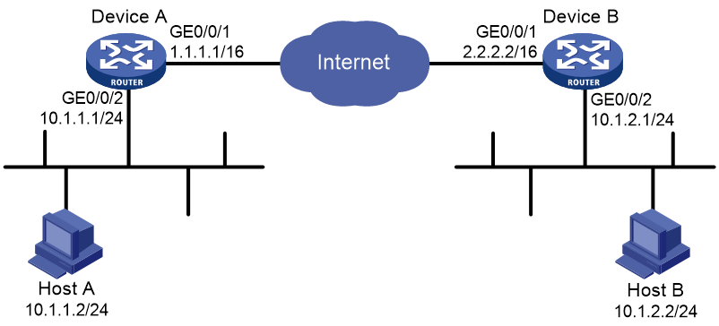
Establish an IPsec tunnel between Device A and Device B to secure data flows between the subnet of Host A (10.1.1.0/24) and the subnet of Host B (10.1.2.0/24).
· Device A and Device B use IKE to negotiate IPsec SAs and use RSA signature authentication.
· The IKE phase 1 negotiation uses the aggressive mode.
· Device A acts as the initiator, and the subnet where Device A resides uses IP addresses dynamically allocated.
Figure 1 Network diagram

Procedures
Make sure the following tasks have been completed:
· Device A has obtained CA certificate ca.cer and local certificate server1.pfx.
· Device B has obtained CA certificate ca.cer and local certificate server2.pfx.
Configuring Device A
# Assign an IP address to each interface. (Details not shown.)
# Configure IPv4 advanced ACL 3101 to identify traffic from subnet 10.1.1.0/24 to subnet 10.1.2.0/24.
<DeviceA> system-view
[DeviceA] acl advanced 3101
[DeviceA-acl-ipv4-adv-3101] rule permit ip source 10.1.1.0 0.0.0.255 destination 10.1.2.0 0.0.0.255
[DeviceA-acl-ipv4-adv-3101] quit
# Create an IPsec transform set named tran1.
[DeviceA] ipsec transform-set tran1
# Set the packet encapsulation mode to tunnel.
[DeviceA-ipsec-transform-set-tran1] encapsulation-mode tunnel
# Use the ESP protocol for the IPsec transform set.
[DeviceA-ipsec-transform-set-tran1] protocol esp
# Specify the encryption and authentication algorithms.
[DeviceA-ipsec-transform-set-tran1] esp encryption-algorithm des-cbc
[DeviceA-ipsec-transform-set-tran1] esp authentication-algorithm sha1
[DeviceA-ipsec-transform-set-tran1] quit
# Create a PKI domain named domain1.
[DeviceA] pki domain domain1
[DeviceA-pki-domain-domain1] undo crl check enable
[DeviceA-pki-domain-domain1] quit
# Import CA certificate ca.cer and local certificate server1.pfx to the PKI domain.
[DeviceA] pki import domain domain1 der ca filename ca.cer
[DeviceA] pki import domain domain1 p12 local filename server1.pfx
# Configure a certificate-based access control policy named policy1.
[DeviceA] pki certificate access-control-policy policy1
[DeviceA-pki-cert-acp-policy1] rule 1 permit group1
[DeviceA-pki-cert-acp-policy1] quit
# Configure a certificate attribute rule.
[DeviceA] pki certificate attribute-group group1
[DeviceA-pki-cert-attribute-group-group1] attribute 1 subject-name dn ctn 1
[DeviceA-pki-cert-attribute-group-group1] quit
A peer certificate is valid only if it contains the specified string (1 in this example) in the DN attribute of the subject name field.
# Create an IKE profile named profile1.
[DeviceA] ike profile profile1
# Specify PKI domain domain1 for the IKE profile.
[DeviceA-ike-profile-profile1] certificate domain domain1
# Specify the IKE negotiation mode in phase 1 as the aggressive mode.
[DeviceA-ike-profile-profile1] exchange-mode aggressive
# Specify the DN in the local certificate as the local ID.
[DeviceA-ike-profile-profile1] local-identity dn
# Specify the DN in the peer's digital certificate as the peer ID for IKE profile matching.
[DeviceA-ike-profile-profile1] match remote certificate policy1
[DeviceA-ike-profile-profile1] quit
# Create an IKE proposal numbered 10.
[DeviceA] ike proposal 10
# Set the authentication algorithm to HMAC-MD5.
[DeviceA-ike-proposal-10] authentication-algorithm md5
# Specify the RSA authentication method.
[DeviceA-ike-proposal-10] authentication-method rsa-signature
[DeviceA-ike-proposal-10] quit
# Create an IKE-based IPsec policy entry. Specify the policy name as map1 and set the sequence number to 10.
[DeviceA] ipsec policy map1 10 isakmp
# Specify the remote IP address of the IPsec tunnel as 2.2.2.2.
[DeviceA-ipsec-policy-isakmp-map1-10] remote-address 2.2.2.2
# Specify IPsec transform set tran1 for the IPsec policy.
[DeviceA-ipsec-policy-isakmp-map1-10] transform-set tran1
# Specify ACL 3101 to identify the traffic to be protected.
[DeviceA-ipsec-policy-isakmp-map1-10] security acl 3101
# Specify IKE profile profile1 for the IPsec policy.
[DeviceA-ipsec-policy-isakmp-map1-10] ike-profile profile1
[DeviceA-ipsec-policy-isakmp-map1-10] quit
# Apply IPsec policy map1 to GigabitEthernet 0/0/1.
[DeviceA] interface gigabitethernet 0/0/1
[DeviceA-GigabitEthernet0/0/1] ipsec apply policy map1
[DeviceA-GigabitEthernet0/0/1] quit
# Configure a static route to the subnet where Host B resides. This example uses 1.1.1.2 as the next hop IP address.
[DeviceA] ip route-static 10.1.2.0 255.255.255.0 1.1.1.2
Configuring Device B
# Assign an IP address to each interface. (Details not shown.)
# Configure IPv4 advanced ACL 3101 to identify the traffic from subnet 10.1.2.0/ 24 to subnet 10.1.1.0/24.
<DeviceB> system-view
[DeviceB] acl advanced 3101
[DeviceB-acl-ipv4-adv-3101] rule permit ip source 10.1.2.0 0.0.0.255 destination 10.1.1.0 0.0.0.255
[DeviceB-acl-ipv4-adv-3101] quit
# Create an IPsec transform set named tran1.
[DeviceB] ipsec transform-set tran1
# Set the packet encapsulation mode to tunnel.
[DeviceB-ipsec-transform-set-tran1] encapsulation-mode tunnel
# Use the ESP protocol for the IPsec transform set.
[DeviceB-ipsec-transform-set-tran1] protocol esp
# Specify the encryption and authentication algorithms.
[DeviceB-ipsec-transform-set-tran1] esp encryption-algorithm des-cbc
[DeviceB-ipsec-transform-set-tran1] esp authentication-algorithm sha1
[DeviceB-ipsec-transform-set-tran1] quit
# Create a PKI domain named domain2.
[DeviceB] pki domain domain2
[DeviceB-pki-domain-domain2] undo crl check enable
[DeviceB-pki-domain-domain2] quit
# Import CA certificate ca.cer and local certificate server2.pfx to the PKI domain.
[DeviceB] pki import domain domain2 der ca filename ca.cer
[DeviceB] pki import domain domain2 p12 local filename server2.pfx
# Configure a certificate-based access control policy named policy1.
[DeviceB] pki certificate access-control-policy policy1
[DeviceB-pki-cert-acp-policy1] rule 1 permit group1
[DeviceB-pki-cert-acp-policy1] quit
# Configure a certificate attribute rule.
[DeviceB] pki certificate attribute-group group1
[DeviceB-pki-cert-attribute-group-group1] attribute 1 subject-name dn ctn 1
[DeviceB-pki-cert-attribute-group-group1] quit
A peer certificate is valid only if it contains the specified string (1 in this example) in the DN attribute of the subject name field.
# Create an IKE profile named profile2.
[DeviceB] ike profile profile2
# Specify PKI domain domain2 for the IKE profile.
[DeviceB-ike-profile-profile2] certificate domain domain2
# Specify the IKE negotiation mode in phase 1 as the aggressive mode.
[DeviceB-ike-profile-profile2] exchange-mode aggressive
# Specify the DN in the local certificate as the local ID.
[DeviceB-ike-profile-profile2] local-identity dn
# Specify the DN in the peer's digital certificate as the peer ID for IKE profile matching.
[DeviceB-ike-profile-profile2] match remote certificate policy1
[DeviceB-ike-profile-profile2] quit
# Create an IKE proposal numbered 10.
[DeviceB] ike proposal 10
# Set the authentication algorithm to HMAC-MD5.
[DeviceB-ike-proposal-10] authentication-algorithm md5
# Specify the RSA authentication method.
[DeviceB-ike-proposal-10] authentication-method rsa-signature
[DeviceB-ike-proposal-10] quit
# Create an IPsec policy template entry. Specify the template name as template1 and set the sequence number to 1.
[DeviceB] ipsec policy-template template1 1
# Specify IPsec transform set tran1 for the IPsec policy.
[DeviceB-ipsec-policy-template-template1-1] transform-set tran1
# Specify ACL 3101 to identify the traffic to be protected.
[DeviceB-ipsec-policy-template-template1-1] security acl 3101
# Specify IKE profile profile2 for the IPsec policy template.
[DeviceB-ipsec-policy-template-template1-1] ike-profile profile2
[DeviceB-ipsec-policy-template-template1-1] quit
# Create an IKE-based IPsec policy entry by using IPsec policy template template1. Specify the policy name as use1 and set the sequence number to 1.
[DeviceB] ipsec policy use1 1 isakmp template template1
# Apply IPsec policy use1 to GigabitEthernet 0/0/1.
[DeviceB] interface gigabitethernet 0/0/1
[DeviceB-GigabitEthernet0/0/1] ipsec apply policy use1
[DeviceB-GigabitEthernet0/0/1] quit
# Configure a static route to Host A. This example uses 2.2.2.1 as the next hop IP address.
[DeviceB] ip route-static 10.1.1.0 255.255.255.0 2.2.2.1
Verifying the configuration
After above configuration, IKE negotiation is triggered between Device A and Device B when there is traffic between subnet 10.1.1.0/24 and subnet 10.1.2.0/24.
# Display the IKE proposal configuration on Device A and Device B.
[DeviceA] display ike proposal
Priority Authentication Authentication Encryption Diffie-Hellman Duration
method algorithm algorithm group (seconds)
----------------------------------------------------------------------------
10 RSA-SIG MD5 DES-CBC Group 1 86400
default PRE-SHARED-KEY SHA1 DES-CBC Group 1 86400
[DeviceB] display ike proposal
Priority Authentication Authentication Encryption Diffie-Hellman Duration
method algorithm algorithm group (seconds)
----------------------------------------------------------------------------
10 RSA-SIG MD5 DES-CBC Group 1 86400
default PRE-SHARED-KEY SHA1 DES-CBC Group 1 86400
# Display the IKE SA on Device A.
[DeviceA] display ike sa
Connection-ID Remote Flag DOI
------------------------------------------------------------------
1 2.2.2.2 RD IPsec
Flags:
RD--READY RL--REPLACED FD-FADING RK-REKEY
# Display IPsec SA information on Device A.
[DeviceA] display ipsec sa
-------------------------------
Interface: GigabitEthernet0/0/1
-------------------------------
-----------------------------
IPsec policy: map1
Sequence number: 10
Mode: ISAKMP
-----------------------------
Tunnel id: 0
Encapsulation mode: tunnel
Perfect Forward Secrecy:
Inside VPN:
Extended Sequence Numbers enable: N
Traffic Flow Confidentiality enable: N
Path MTU: 1456
Tunnel:
local address: 1.1.1.1
remote address: 2.2.2.2
Flow:
sour addr: 10.1.1.0/255.255.255.0 port: 0 protocol: ip
dest addr: 10.1.2.0/255.255.255.0 port: 0 protocol: ip
[Inbound ESP SAs]
SPI: 3264152513 (0xc28f03c1)
Connection ID: 90194313219
Transform set: ESP-ENCRYPT-DES-CBC ESP-AUTH-SHA1
SA duration (kilobytes/sec): 1843200/3600
SA remaining duration (kilobytes/sec): 1843200/3484
Max received sequence-number:
Anti-replay check enable: Y
Anti-replay window size: 64
UDP encapsulation used for NAT traversal: N
Status: Active
[Outbound ESP SAs]
SPI: 738451674 (0x2c03e0da)
Connection ID: 64424509441
Transform set: ESP-ENCRYPT-DES-CBC ESP-AUTH-SHA1
SA duration (kilobytes/sec): 1843200/3600
SA remaining duration (kilobytes/sec): 1843200/3484
Max sent sequence-number:
UDP encapsulation used for NAT traversal: N
Status: Active
# Display information about the IKE SA and IPsec SA on Device B. (Details not shown.)
Example: Configuring GM main mode IKE with SM2-DE digital envelope authentication
Network configuration
Establish an IPsec tunnel between Device A and Device B to secure data flows between the subnet of Host A (10.1.1.0/24) and the subnet of Host B (10.1.2.0/24).
Device A and Device B use IKE to negotiate IPsec SAs, use SM2-DE signature authentication, and use the GM main mode for phase 1 IKE negotiation.
Figure 2 Network diagram
Procedures
Restrictions and guidelines
The SM1 algorithm is supported only if the following network data encryption modules are installed: SIC-CNDE, SIC-CNDE-SJK, SIC-4G-CNDE-SJK, SIC-D4G-CNDE-SJK, HMIM-CNDE-SJK
Make sure the following tasks have been completed:
· Device A has obtained CA certificate ca.cer and local certificate server1.pfx.
· Device B has obtained CA certificate ca.cer and local certificate server2.pfx.
Configuring Device A
# Assign an IP address to each interface. (Details not shown.)
# Configure IPv4 advanced ACL 3101 to identify the traffic from subnet 10.1.1.0/ 24 to subnet 10.1.2.0/24.
<DeviceA> system-view
[DeviceA] acl advanced 3101
[DeviceA-acl-ipv4-adv-3101] rule permit ip source 10.1.1.0 0.0.0.255 destination 10.1.2.0 0.0.0.255
[DeviceA-acl-ipv4-adv-3101] quit
# Create an IPsec transform set named tran1.
[DeviceA] ipsec transform-set tran1
# Set the packet encapsulation mode to tunnel.
[DeviceA-ipsec-transform-set-tran1] encapsulation-mode tunnel
# Use the ESP protocol for the IPsec transform set.
[DeviceA-ipsec-transform-set-tran1] protocol esp
# Specify the encryption and authentication algorithms.
[DeviceA-ipsec-transform-set-tran1] esp encryption-algorithm sm4-cbc
[DeviceA-ipsec-transform-set-tran1] esp authentication-algorithm sm3
[DeviceA-ipsec-transform-set-tran1] quit
# Create a PKI domain named domain1.
[DeviceA] pki domain domain1
[DeviceA-pki-domain-domain1] undo crl check enable
[DeviceA-pki-domain-domain1] quit
# Import CA certificate ca.cer and local certificate server1.pfx to the PKI domain.
[DeviceA] pki import domain domain1 der ca filename ca.cer
[DeviceA] pki import domain domain1 p12 local filename server1.pfx
# Create an IKE proposal numbered 10.
[DeviceA] ike proposal 10
# Set the authentication method to SM2-DE.
[DeviceA-ike-proposal-10] authentication-method sm2-de
# Set the authentication algorithm to SM3.
[DeviceA-ike-proposal-10] authentication-algorithm sm3
# Specify the encryption algorithm to SM4-CBC.
[DeviceA-ike-proposal-10] encryption-algorithm sm4-cbc
[DeviceA-ike-proposal-10] quit
# Create an IKE profile named profile1.
[DeviceA] ike profile profile1
# Specify the phase 1 IKE negotiation mode as the GM main mode.
[DeviceA-ike-profile-profile1] exchange-mode gm-main
# Specify PKI domain domain1 for the IKE profile.
[DeviceA-ike-profile-profile1] certificate domain domain1
# Create an IKE proposal numbered 10.
[DeviceA-ike-profile-profile1] proposal 10
# Configure the local ID as IP address 1.1.1.1.
[DeviceA-ike-profile-profile1] local-identity address 1.1.1.1
# Configure a peer ID with the identity type as IP address and the value as 2.2.2.2/16.
[DeviceA-ike-profile-profile1] match remote identity address 2.2.2.2 255.255.0.0
[DeviceA-ike-profile-profile1] quit
# Create an IKE-based IPsec policy entry. Specify the policy name as map1 and set the sequence number to 10.
[DeviceA] ipsec policy map1 10 isakmp
# Specify the remote IP address of the IPsec tunnel as 2.2.2.2.
[DeviceA-ipsec-policy-isakmp-map1-10] remote-address 2.2.2.2
# Specify ACL 3101 to identify the traffic to be protected.
[DeviceA-ipsec-policy-isakmp-map1-10] security acl 3101
# Specify IPsec transform set tran1 for the IPsec policy.
[DeviceA-ipsec-policy-isakmp-map1-10] transform-set tran1
# Specify IKE profile profile1 for the IPsec policy.
[DeviceA-ipsec-policy-isakmp-map1-10] ike-profile profile1
[DeviceA-ipsec-policy-isakmp-map1-10] quit
# Apply IPsec policy map1 to GigabitEthernet 0/0/1.
[DeviceA] interface gigabitethernet 0/0/1
[DeviceA-GigabitEthernet0/0/1] ipsec apply policy map1
[DeviceA-GigabitEthernet0/0/1] quit
# Configure a static route to the subnet where Host B resides. This example uses 1.1.1.2 as the next hop IP address.
[DeviceA] ip route-static 10.1.2.0 255.255.255.0 1.1.1.2
Configuring Device B
# Assign an IP address to each interface. (Details not shown.)
# Configure IPv4 advanced ACL 3101 to identify the traffic from subnet 10.1.2.0/24 to subnet 10.1.1.0/24.
<DeviceB> system-view
[DeviceB] acl advanced 3101
[DeviceB-acl-ipv4-adv-3101] rule permit ip source 10.1.2.0 0.0.0.255 destination 10.1.1.0 0.0.0.255
[DeviceB-acl-ipv4-adv-3101] quit
# Create an IPsec transform set named tran1.
[DeviceB] ipsec transform-set tran1
# Set the packet encapsulation mode to tunnel.
[DeviceB-ipsec-transform-set-tran1] encapsulation-mode tunnel
# Use the ESP protocol for the IPsec transform set.
[DeviceB-ipsec-transform-set-tran1] protocol esp
# Specify the encryption and authentication algorithms.
[DeviceB-ipsec-transform-set-tran1] esp encryption-algorithm sm4-cbc
[DeviceB-ipsec-transform-set-tran1] esp authentication-algorithm sm3
[DeviceB-ipsec-transform-set-tran1] quit
# Create a PKI domain named domain2.
[DeviceB] pki domain domain2
[DeviceB-pki-domain-domain2] undo crl check enable
[DeviceB-pki-domain-domain2] quit
# Import CA certificate ca.cer and local certificate server2.pfx to the PKI domain.
[DeviceB] pki import domain domain2 der ca filename ca.cer
[DeviceB] pki import domain domain2 p12 local filename server2.pfx
# Create an IKE proposal numbered 10.
[DeviceB] ike proposal 10
# Set the authentication method to SM2-DE.
[DeviceB-ike-proposal-10] authentication-method sm2-de
# Set the authentication algorithm to SM3.
[DeviceB-ike-proposal-10] authentication-algorithm sm3
# Specify the encryption algorithm to SM4-CBC.
[DeviceB-ike-proposal-10] encryption-algorithm sm4-cbc
[DeviceB-ike-proposal-10] quit
# Create an IKE profile named profile1.
[DeviceB] ike profile profile1
# Specify the phase 1 IKE negotiation mode as the GM main mode.
[DeviceB-ike-profile-profile1] exchange-mode gm-main
# Specify PKI domain domain2 for the IKE profile.
[DeviceB-ike-profile-profile1] certificate domain domain2
# Create an IKE proposal numbered 10.
[DeviceB-ike-profile-profile1] proposal 10
# Configure the local ID as IP address 2.2.2.2.
[DeviceB-ike-profile-profile1] local-identity address 2.2.2.2
# Configure a peer ID with the identity type as IP address and the value as 1.1.1.1/16.
[DeviceB-ike-profile-profile1] match remote identity address 1.1.1.1 255.255.0.0
[DeviceB-ike-profile-profile1] quit
# Create an IKE-based IPsec policy entry. Specify the policy name as use1 and set the sequence number to 10.
[DeviceB] ipsec policy use1 10 isakmp
# Specify the remote IP address of the IPsec tunnel as 1.1.1.1.
[DeviceB-ipsec-policy-isakmp-use1-10] remote-address 1.1.1.1
# Specify ACL 3101 to identify the traffic to be protected.
[DeviceB-ipsec-policy-isakmp-use1-10] security acl 3101
# Specify IPsec transform set tran1 for the IPsec policy.
[DeviceB-ipsec-policy-isakmp-use1-10] transform-set tran1
# Specify IKE profile profile1 for the IPsec policy.
[DeviceB-ipsec-policy-isakmp-use1-10] ike-profile profile1
[DeviceB-ipsec-policy-isakmp-use1-10] quit
# Apply IPsec policy use1 to GigabitEthernet 0/0/1.
[DeviceB] interface gigabitethernet 0/0/1
[DeviceB-GigabitEthernet0/0/1] ipsec apply policy use1
# Configure a static route to Host A. This example uses 2.2.2.1 as the next hop IP address.
[DeviceB] ip route-static 10.1.1.0 255.255.255.0 2.2.2.1
Verifying the configuration
After above configuration, IKE negotiation is triggered between Device A and Device B when there is traffic between subnet 10.1.1.0/24 and subnet 10.1.2.0/24.
# Display the IKE proposal configuration on Device A and Device B.
[DeviceA] display ike proposal
Priority Authentication Authentication Encryption Diffie-Hellman Duration
method algorithm algorithm group (seconds)
----------------------------------------------------------------------------
10 SM2-DE SM3 SM4-CBC Group 1 86400
default PRE-SHARED-KEY SHA1 DES-CBC Group 1 86400
[DeviceB] display ike proposal
Priority Authentication Authentication Encryption Diffie-Hellman Duration
method algorithm algorithm group (seconds)
----------------------------------------------------------------------------
10 SM2-DE SM3 SM4-CBC Group 1 86400
default PRE-SHARED-KEY SHA1 DES-CBC Group 1 86400
# Display the IKE SA on Device A.
[DeviceA] display ike sa
Connection-ID Remote Flag DOI
------------------------------------------------------------------
1 2.2.2.2 RD IPsec
Flags:
RD--READY RL--REPLACED FD-FADING RK-REKEY
# Display IPsec SA information on Device A.
[DeviceA] display ipsec sa
-------------------------------
Interface: GigabitEthernet0/0/1
-------------------------------
-----------------------------
IPsec policy: map1
Sequence number: 10
Mode: ISAKMP
-----------------------------
Tunnel id: 0
Encapsulation mode: tunnel
Perfect Forward Secrecy:
Inside VPN:
Extended Sequence Numbers enable: N
Traffic Flow Confidentiality enable: N
Path MTU: 1456
Tunnel:
local address: 1.1.1.1
remote address: 2.2.2.2
Flow:
sour addr: 10.1.1.0/255.255.255.0 port: 0 protocol: ip
dest addr: 10.1.2.0/255.255.255.0 port: 0 protocol: ip
[Inbound ESP SAs]
SPI: 1451246811 (0x568044db)
Connection ID: 90194313219
Transform set: ESP-ENCRYPT-SM4-CBC ESP-AUTH-SM3
SA duration (kilobytes/sec): 1843200/3600
SA remaining duration (kilobytes/sec): 1843200/3484
Max received sequence-number:
Anti-replay check enable: Y
Anti-replay window size: 64
UDP encapsulation used for NAT traversal: N
Status: Active
[Outbound ESP SAs]
SPI: 2692887942 (0xa0823586)
Connection ID: 64424509441
Transform set: ESP-ENCRYPT-SM4-CBC ESP-AUTH-SM3
SA duration (kilobytes/sec): 1843200/3600
SA remaining duration (kilobytes/sec): 1843200/3484
Max sent sequence-number:
UDP encapsulation used for NAT traversal: N
Status: Active
# Display information about the IKE SA and IPsec SA on Device B. (Details not shown.)
Example: Configuring IKEv2 with RSA signature authentication
Network configuration
Establish an IPsec tunnel between Device A and Device B to secure data flows between the subnet of Host A (10.1.1.0/24) and the subnet of Host B (10.1.2.0/24).
· Device A and Device B use IKEv2 to negotiate IPsec SAs.
· Both Device A and Device B use RSA signature authentication.
· Device A acts as the initiator, and the subnet where Device A resides uses IP addresses dynamically allocated.
Figure 3 Network diagram

Procedures
Make sure the following tasks have been completed:
· Device A has obtained CA certificate ca.cer and local certificate server1.pfx.
· Device B has obtained CA certificate ca.cer and local certificate server2.pfx.
Configuring Device A
# Assign an IP address to each interface. (Details not shown.)
# Define an ACL to identify traffic from subnet 10.1.1.0/24 to subnet 10.1.2.0/24.
<DeviceA> system-view
[DeviceA] acl advanced 3101
[DeviceA-acl-ipv4-adv-3101] rule permit ip source 10.1.1.0 0.0.0.255 destination 10.1.2.0 0.0.0.255
[DeviceA-acl-ipv4-adv-3101] quit
# Create an IPsec transform set named tran1.
[DeviceA] ipsec transform-set tran1
# Set the packet encapsulation mode to tunnel.
[DeviceA-ipsec-transform-set-tran1] encapsulation-mode tunnel
# Use the ESP protocol for the IPsec transform set.
[DeviceA-ipsec-transform-set-tran1] protocol esp
# Specify the encryption and authentication algorithms.
[DeviceA-ipsec-transform-set-tran1] esp encryption-algorithm des-cbc
[DeviceA-ipsec-transform-set-tran1] esp authentication-algorithm sha1
[DeviceA-ipsec-transform-set-tran1] quit
# Create a PKI domain named domain1.
[DeviceA] pki domain domain1
[DeviceA-pki-domain-domain1] undo crl check enable
[DeviceA-pki-domain-domain1] quit
# Import CA certificate ca.cer and local certificate server1.pfx to the PKI domain.
[DeviceA] pki import domain domain1 der ca filename ca.cer
[DeviceA] pki import domain domain1 p12 local filename server1.pfx
# Configure a certificate-based access control policy named policy1.
[DeviceA] pki certificate access-control-policy policy1
[DeviceA-pki-cert-acp-policy1] rule 1 permit group1
[DeviceA-pki-cert-acp-policy1] quit
# Configure a certificate attribute rule.
[DeviceA] pki certificate attribute-group group1
[DeviceA-pki-cert-attribute-group-group1] attribute 1 subject-name dn ctn 1
[DeviceA-pki-cert-attribute-group-group1] quit
A peer certificate is valid only if it contains the specified string (1 in this example) in the DN attribute of the subject name field.
# Create an IKEv2 profile named profile1.
[DeviceA] ikev2 profile profile1
# Specify the local authentication method as RSA signature authentication.
[DeviceA-ikev2-profile-profile1] authentication-method local rsa-signature
# Specify the remote authentication method as RSA signature authentication.
[DeviceA-ikev2-profile-profile1] authentication-method remote rsa-signature
# Specify PKI domain domain1 for the IKE profile.
[DeviceA-ikev2-profile-profile1] certificate domain domain1
# Specify the DN in the local certificate as the local ID.
[DeviceA-ikev2-profile-profile1] identity local dn
# Specify the DN in the peer's digital certificate as the peer ID for IKE profile matching.
[DeviceA-ikev2-profile-profile1] match remote certificate policy1
[DeviceA-ikev2-profile-profile1] quit
# Create an IKEv2 proposal numbered 10.
[DeviceA] ikev2 proposal 10
# Set the integrity protection algorithm to HMAC-MD5.
[DeviceA-ikev2-proposal-10] integrity md5
# Set the encryption algorithm to 3DES.
[DeviceA-ikev2-proposal-10] encryption 3des-cbc
# Specify the DH group as Group 1.
[DeviceA-ikev2-proposal-10] dh group1
# Set the PRF algorithm to HMAC-MD5.
[DeviceA-ikev2-proposal-10] prf md5
[DeviceA-ikev2-proposal-10] quit
# Create an IKEv2 policy named 1.
[DeviceA] ikev2 policy 1
# Specify IKEv2 proposal 10 for the IKEv2 policy.
[DeviceA-ikev2-policy-1] proposal 10
[DeviceA-ikev2-policy-1] quit
# Create an IKEv2-based IPsec policy entry. Specify the policy name as map1 and set the sequence number to 10.
[DeviceA] ipsec policy map1 10 isakmp
# Specify the remote IP address of the IPsec tunnel as 2.2.2.2.
[DeviceA-ipsec-policy-isakmp-map1-10] remote-address 2.2.2.2
# Specify IPsec transform set tran1 for the IPsec policy.
[DeviceA-ipsec-policy-isakmp-map1-10] transform-set tran1
# Specify ACL 3101 to identify the traffic to be protected.
[DeviceA-ipsec-policy-isakmp-map1-10] security acl 3101
# Specify IKEv2 profile profile1 for the IPsec policy.
[DeviceA-ipsec-policy-isakmp-map1-10] ikev2-profile profile1
[DeviceA-ipsec-policy-isakmp-map1-10] quit
# Apply IPsec policy map1 to GigabitEthernet 0/0/1.
[DeviceA] interface gigabitethernet 0/0/1
[DeviceA-GigabitEthernet0/0/1] ipsec apply policy map1
[DeviceA-GigabitEthernet0/0/1] quit
# Configure a static route to the subnet where Host B resides. This example uses 1.1.1.2 as the next hop IP address.
[DeviceA] ip route-static 10.1.2.0 255.255.255.0 1.1.1.2
Configuring Device B
# Assign an IP address to each interface. (Details not shown.)
# Configure IPv4 advanced ACL 3101 to identify the traffic from subnet 10.1.2.0/ 24 to subnet 10.1.1.0/24.
[DeviceB] acl advanced 3101
[DeviceB-acl-ipv4-adv-3101] rule permit ip source 10.1.2.0 0.0.0.255 destination 10.1.1.0 0.0.0.255
[DeviceB-acl-ipv4-adv-3101] quit
# Create an IPsec transform set named tran1.
[DeviceB] ipsec transform-set tran1
# Set the packet encapsulation mode to tunnel.
[DeviceB-ipsec-transform-set-tran1] encapsulation-mode tunnel
# Use the ESP protocol for the IPsec transform set.
[DeviceB-ipsec-transform-set-tran1] protocol esp
# Specify the encryption and authentication algorithms.
[DeviceB-ipsec-transform-set-tran1] esp encryption-algorithm des-cbc
[DeviceB-ipsec-transform-set-tran1] esp authentication-algorithm sha1
[DeviceB-ipsec-transform-set-tran1] quit
# Create a PKI domain named domain2.
[DeviceB] pki domain domain2
[DeviceB-pki-domain-domain2] undo crl check enable
[DeviceB-pki-domain-domain2] quit
# Import CA certificate ca.cer and local certificate server2.pfx to the PKI domain.
[DeviceB] pki import domain domain2 der ca filename ca.cer
[DeviceB] pki import domain domain2 p12 local filename server2.pfx
# Configure a certificate-based access control policy named policy1.
[DeviceB] pki certificate access-control-policy policy1
[DeviceB-pki-cert-acp-policy1] rule 1 permit group1
[DeviceB-pki-cert-acp-policy1] quit
# Configure a certificate attribute rule.
[DeviceB] pki certificate attribute-group group1
[DeviceB-pki-cert-attribute-group-group1] attribute 1 subject-name dn ctn 1
[DeviceB-pki-cert-attribute-group-group1] quit
A peer certificate is valid only if it contains the specified string (1 in this example) in the DN attribute of the subject name field.
# Create an IKEv2 profile named profile2.
[DeviceB] ikev2 profile profile2
# Specify the local authentication method as RSA signature authentication.
[DeviceB-ikev2-profile-profile2] authentication-method local rsa-signature
# Specify the remote authentication method as RSA signature authentication.
[DeviceB-ikev2-profile-profile2] authentication-method remote rsa-signature
# Specify the DN in the local certificate as the local ID.
[DeviceB-ikev2-profile-profile2] identity local dn
# Specify the DN in the peer's digital certificate as the peer ID for IKE profile matching.
[DeviceB-ikev2-profile-profile2] match remote certificate policy1
[DeviceB-ikev2-profile-profile2] quit
# Create an IKEv2 proposal numbered 10.
[DeviceB] ikev2 proposal 10
# Set the integrity protection algorithm to HMAC-MD5.
[DeviceB-ikev2-proposal-10] integrity md5
# Set the encryption algorithm to 3DES.
[DeviceB-ikev2-proposal-10] encryption 3des-cbc
# Specify the DH group as Group 1.
[DeviceB-ikev2-proposal-10] dh group1
# Set the PRF algorithm to HMAC-MD5.
[DeviceB-ikev2-proposal-10] prf md5
[DeviceB-ikev2-proposal-10] quit
# Create an IKEv2 policy named 1.
[DeviceB] ikev2 policy 1
# Specify IKEv2 proposal 10 for the IKEv2 policy.
[DeviceB-ikev2-policy-1] proposal 10
[DeviceB-ikev2-policy-1] quit
# Create an IPsec policy template entry. Specify the template name as template1 and set the sequence number to 1.
[DeviceB] ipsec policy-template template1 1
# Specify the remote IP address of the IPsec tunnel as 1.1.1.1.
[DeviceB-ipsec-policy-template-template1-1] remote-address 1.1.1.1
# Specify ACL 3101 to identify the traffic to be protected.
[DeviceB-ipsec-policy-template-template1-1] security acl 3101
# Specify IPsec transform set tran1 for the IPsec policy.
[DeviceB-ipsec-policy-template-template1-1] transform-set tran1
# Specify IKEv2 profile profile2 for the IPsec policy template.
[DeviceB-ipsec-policy-template-template1-1] ikev2-profile profile2
[DeviceB-ipsec-policy-template-template1-1] quit
# Create an IKE-based IPsec policy entry by using IPsec policy template template1. Specify the policy name as use1 and set the sequence number to 1.
[DeviceB] ipsec policy use1 1 isakmp template template1
# Apply IPsec policy use1 to GigabitEthernet0/0/1.
[DeviceB] interface gigabitethernet 0/0/1
[DeviceB-GigabitEthernet0/0/1] ipsec apply policy use1
[DeviceB-GigabitEthernet0/0/1] quit
# Configure a static route to Host A. This example uses 2.2.2.1 as the next hop IP address.
[DeviceB] ip route-static 10.1.1.0 255.255.255.0 2.2.2.1
Verifying the configuration
After above configuration, IKEv2 negotiation is triggered between Device A and Device B when there is traffic between subnet 10.1.1.0/24 and subnet 10.1.2.0/24.
# Display the IKEv2 proposal configuration on Device A and Device B.
[DeviceA] display ikev2 proposal 10
IKEv2 proposal : 10
Encryption : 3DES-CBC
Integrity : MD5
PRF : MD5
DH Group : MODP768/Group1
[DeviceB] display ikev2 proposal 10
IKEv2 proposal : 10
Encryption : 3DES-CBC
Integrity : MD5
PRF : MD5
DH Group : MODP768/Group1
# Display the IKEv2 policy configuration on Device A and Device B.
[DeviceA] display ikev2 policy 1
IKEv2 policy : 1
Priority: 100
Match Local : any
Match VRF : public
Proposal : 10
[DeviceB] display ikev2 policy 1
IKEv2 policy : 1
Priority: 100
Match Local : any
Match VRF : public
Proposal : 10
# Display the IKEv2 SA on Device A.
[DeviceA] display ikev2 sa
Tunnel ID Local Remote Status
---------------------------------------------------------------------------
1 1.1.1.1/500 2.2.2.2/500 EST
Status:
IN-NEGO: Negotiating, EST: Established, DEL:Deleting
# Display IPsec SA information on Device A.
[DeviceA] display ipsec sa
-------------------------------
Interface: GigabitEthernet0/0/1
-------------------------------
-----------------------------
IPsec policy: map1
Sequence number: 10
Mode: ISAKMP
-----------------------------
Tunnel id: 0
Encapsulation mode: tunnel
Perfect Forward Secrecy:
Inside VPN:
Extended Sequence Numbers enable: N
Traffic Flow Confidentiality enable: N
Path MTU: 1456
Tunnel:
local address: 1.1.1.1
remote address: 2.2.2.2
Flow:
sour addr: 10.1.1.0/255.255.255.0 port: 0 protocol: ip
dest addr: 10.1.2.0/255.255.255.0 port: 0 protocol: ip
[Inbound ESP SAs]
SPI: 3264152513 (0xc28f03c1)
Connection ID: 141733920771
Transform set: ESP-ENCRYPT-DES-CBC ESP-AUTH-SHA1
SA duration (kilobytes/sec): 1843200/3600
SA remaining duration (kilobytes/sec): 1843200/3484
Max received sequence-number:
Anti-replay check enable: Y
Anti-replay window size: 64
UDP encapsulation used for NAT traversal: N
Status: Active
[Outbound ESP SAs]
SPI: 738451674 (0x2c03e0da)
Connection ID: 141733920770
Transform set: ESP-ENCRYPT-DES-CBC ESP-AUTH-SHA1
SA duration (kilobytes/sec): 1843200/3600
SA remaining duration (kilobytes/sec): 1843200/3484
Max sent sequence-number:
UDP encapsulation used for NAT traversal: N
Status: Active
# Display information about the IKEv2 SA, and IPsec SA on Device B. (Details not shown.)