- Table of Contents
-
- H3C MSR1000[2600][3600] Routers Configuration Examples All-in-One-R9141-6W100
- 00-Preface
- 01-Local 802.1X Authentication Configuration Examples
- 02-RADIUS-Based 802.1X Authentication Configuration Examples
- 03-AAA Configuration Examples
- 04-ACL Configuration Examples
- 05-MPLS over ADVPN Configuration Examples
- 06-ARP Attack Protection Configuration Examples
- 07-BFD Configuration Examples
- 08-Basic BGP Configuration Examples
- 09-BGP Route Attribute-Based Route Selection Configuration Examples
- 10-EAA Monitor Policy Configuration Examples
- 11-GRE with OSPF Configuration Examples
- 12-HoVPN Configuration Examples
- 13-IGMP Snooping Configuration Examples
- 14-IGMP Configuration Examples
- 15-IPsec Configuration Examples
- 16-IPsec Digital Certificate Authentication Configuration Examples
- 17-IPv6 IS-IS Configuration Examples
- 18-IPv6 over IPv4 GRE Tunnel Configuration Examples
- 19-IPv6 over IPv4 Manual Tunnel with OSPFv3 Configuration Examples
- 20-IS-IS Configuration Examples
- 21-Combined ISATAP Tunnel and 6to4 Tunnel Configuration Examples
- 22-L2TP over IPsec Configuration Examples
- 23-Multi-Instance L2TP Configuration Examples
- 24-L2TP Multidomain Access Configuration Examples
- 25-MPLS L3VPN Configuration Examples
- 26-MPLS OAM Configuration Examples
- 27-MPLS TE Configuration Examples
- 28-Basic MPLS Configuration Examples
- 29-NAT DNS Mapping Configuration Examples
- 30-NetStream Configuration Examples
- 31-NQA Configuration Examples
- 32-NTP Configuration Examples
- 33-OSPFv3 Configuration Examples
- 34-OSPF Configuration Examples
- 35-OSPF Multi-Process Configuration Examples
- 36-OSPF Multi-Instance Configuration Examples
- 37-Portal Configuration Examples
- 38-PPP Configuration Examples
- 39-RBAC Configuration Examples
- 40-RMON Configuration Examples
- 41-IPv4 NetStream Sampling Configuration Examples
- 42-SNMP Configuration Examples
- 43-SRv6 Configuration Examples
- 44-SSH Configuration Examples
- 45-Tcl Commands Configuration Examples
- 46-VLAN Configuration Examples
- 47-VRRP Configuration Examples
- 48-VXLAN over IPsec Configuration Examples
- 49-WLAN AC Configuration Examples
- 50-Small and Medium-Sized Store Configuration Examples
- 51-Cloudnet VPN Configuration Examples
- 52-Ethernet Link Aggregation Configuration Examples
- 53-Ethernet OAM Configuration Examples
- 54-Outbound Bidirectional NAT Configuration Examples
- 55-NAT Hairpin in C-S Mode Configuration Examples
- 56-Load Sharing NAT Server Configuration Examples
- 57-BIDIR-PIM Configuration Examples
- 58-Control Plane-Based QoS Policy Configuration Examples
- 59-Scheduling a Task Configuration Examples
- 60-Client-Initiated L2TP Tunnel Configuration Examples
- 61-LAC-Auto-Initiated L2TP Tunnel Configuration Examples
- 62-Authorized ARP Configuration Examples
- 63-GTS Configuration Examples
- 64-Traffic Policing Configuration Examples
- 65-Traffic Accounting Configuration Examples
- 66-Mobile Communication Modem Management Configuration Examples
- 67-Port Isolation Configuration Examples
- 68-PBR Configuration Examples
- 69-TFTP Client Software Upgrade Configuration Examples
- 70-FTP Client Software Upgrade Configuration Examples
- 71-FTP Server Software Upgrade Configuration Examples
- 72-Routing Policy Configuration Examples
- 73-Software Upgrade from the BootWare Menu Configuration Examples
- 74-Mirroring Configuration Examples
- Related Documents
-
| Title | Size | Download |
|---|---|---|
| 04-ACL Configuration Examples | 134.60 KB |
|
|
|
H3C Routers |
|
ACL Configuration Examples |
|
|
|
|
Copyright © 2024 New H3C Technologies Co., Ltd. All rights reserved.
No part of this manual may be reproduced or transmitted in any form or by any means without prior written consent of New H3C Technologies Co., Ltd.
Except for the trademarks of New H3C Technologies Co., Ltd., any trademarks that may be mentioned in this document are the property of their respective owners.
The information in this document is subject to change without notice.
Contents
Example: Configuring MAC address-based packet filtering
Example: Configuring IP address-based packet filtering
Example: Configuring TCP protocol-based packet filtering
Introduction
The following information provides ACL-related packet filtering configuration examples.
Prerequisites
The following information applies to Comware 9-based routers. Procedures and information in the examples might be slightly different depending on the software or hardware version of the routers.
The configuration examples were created and verified in a lab environment, and all the devices were started with the factory default configuration. When you are working on a live network, make sure you understand the potential impact of every command on your network.
The following information is provided based on the assumption that you have basic knowledge of ACL.
Example: Configuring MAC address-based packet filtering
Network configuration
As shown in Figure 1, the MAC addresses of video devices in the R&D dept and in the Admin dept are 000f-e2xx-xxxx. Configure an ACL to allow packets from the video devices every day from 8:30 to 18:00.

Software versions used
This configuration example was created and verified on Release 9141P16 of the MSR2630E-X1 router.
Analysis
If the IP address of the video device to be limited is not fixed, use the MAC address to match packets. For multiple video devices with the same MAC address prefix, you can use a MAC address mask to match them.
Procedures
# Assign IP addresses to interfaces.
<Device> system-view
[Device] interface gigabitethernet 0/0/1
[Device-GigabitEthernet0/0/1] ip address 10.1.1.1 24
[Device-GigabitEthernet0/0/1] quit
[Device] interface gigabitethernet 0/0/2
[Device-GigabitEthernet0/0/2] ip address 10.1.2.1 24
[Device-GigabitEthernet0/0/2] quit
[Device] interface gigabitethernet 0/0/3
[Device-GigabitEthernet0/0/3] ip address 200.1.1.2 24
[Device-GigabitEthernet0/0/3] quit
# Define a time range that contains the time section from 8:30 to 18:00 every day.
[Device] time-range time1 8:30 to 18:00 daily
# Create Layer 2 MAC 4000, and configure rules to allow the packets with a MAC address prefix of 000f-e2 during time range time1.
[Device] acl number 4000
[Device-acl-mac-4000] rule permit source-mac 000f-e200-0000 ffff-ff00-0000 time-range time1
[Device-acl-mac-4000] rule deny source-mac 000f-e200-0000 ffff-ff00-0000
[Device-acl-mac-4000] quit
# Apply ACL 4000 to filter the incoming packets on GigabitEthernet 0/0/1 and GigabitEthernet 0/0/2.
[Device] interface gigabitethernet 0/0/1
[Device-GigabitEthernet0/0/1] packet-filter 4000 inbound
[Device-GigabitEthernet0/0/1] quit
[Device] interface gigabitethernet 0/0/2
[Device-GigabitEthernet0/0/2] packet-filter 4000 inbound
[Device-GigabitEthernet0/0/2] quit
# Configure a default route to the external network.
[Device] ip route-static 0.0.0.0 0.0.0.0 200.1.1.1
Verifying the configuration
# Use the display packet-filter command to display ACL application information for packet filtering.
[Device] display packet-filter interface inbound
Interface: GigabitEthernet0/0/1
In-bound policy:
MAC ACL 4000
MAC default action: Permit
Interface: GigabitEthernet0/0/2
In-bound policy:
MAC ACL 4000
MAC default action: Permit
The output shows that GigabitEthernet 0/0/1 and GigabitEthernet 0/0/2 have been successfully applied with an ACL for packet filtering.
From 8:30 to 18:00 every day, the video devices can communicate with the external network. During other times, the video devices cannot communicate with the external network.
Configuration files
#
interface GigabitEthernet0/0/1
port link-mode route
combo enable copper
ip address 10.1.1.1 255.255.255.0
packet-filter 4000 inbound
#
interface GigabitEthernet0/0/2
port link-mode route
combo enable copper
ip address 10.1.2.1 255.255.255.0
packet-filter 4000 inbound
#
interface GigabitEthernet0/0/3
port link-mode route
combo enable copper
ip address 200.1.1.2 255.255.255.0
#
ip route-static 0.0.0.0 0 200.1.1.1
#
time-range time1 08:30 to 18:00 daily
#
acl number 4000
rule 0 permit source-mac 000f-e200-0000 ffff-ff00-0000 time-range time1
rule 5 deny source-mac 000f-e200-0000 ffff-ff00-0000
Example: Configuring IP address-based packet filtering
Network configuration
As shown in Figure 2, the network of a company is divided into three parts: Admin dept, R&D dept, and servers. The network is connected to the Internet through the device. Configure ACLs to meet the following requirements:
· The Admin dept can access the Internet at any time and cannot access the R&D dept.
· The R&D dept can access the servers but cannot access the Internet or the Admin dept during business hours (8:30 to 18:00 on Monday through Friday). During non-business hours, the R&D dept can access the Internet and the servers and cannot access the Admin dept.

Software versions used
This configuration example was created and verified on Release 9141P16 of the MSR2630E-X1 router.
Analysis
· To prevent the Admin dept from accessing the R&D dept, configure an ACL on GigabitEthernet 0/0/4 to deny the incoming packets with the destination IP address on the 10.1.2.0/24 network.
· To allow the R&D dept to access servers during only business hours, configure an ACL on GigabitEthernet 0/0/3 with a time range to permit the incoming packets with the destination IP address on the 10.1.3.0/24 network.
· To prevent the R&D dept from accessing the Admin dept during non-business hours, configure an ACL on GigabitEthernet 0/0/3 to deny the incoming packets with the destination IP address on the subnet 10.1.1.0/24 network.
· By default, ACL rules are matched in their configuration order. In this example, first create the rule to permit the packets with the destination IP address on the 10.1.3.0/24 network, and then create the rule to deny other packets.
Procedures
1. Assign IP addresses to interfaces:
# Assign an IP address to GigabitEthernet 0/0/2.
<Device> system-view
[Device] interface gigabitethernet 0/0/2
[Device-GigabitEthernet0/0/2] ip address 200.1.1.2 24
[Device-GigabitEthernet0/0/2] quit
# Assign IP addresses to other interfaces. (Details not shown.)
2. Configure a default route to the external network:
[Device] ip route-static 0.0.0.0 0.0.0.0 200.1.1.1
3. Configure packet filtering for the Admin dept:
# Create IPv4 advanced ACL 3000.
[Device] acl number 3000
# Configure a rule to deny the packets with the destination IP address on the 10.1.2.0/24 network.
[Device-acl-ipv4-adv-3000] rule deny ip destination 10.1.2.0 0.0.0.255
[Device-acl-ipv4-adv-3000] quit
# Apply ACL 3000 to filter the incoming packets on GigabitEthernet 0/0/4.
[Device] interface gigabitethernet 0/0/4
[Device-GigabitEthernet0/0/4] packet-filter 3000 inbound
[Device-GigabitEthernet0/0/4] quit
4. Configure packet filtering for the R&D dept:
# Create a periodic time range from 8:30 to 18:00 on business days.
[Device] time-range worktime 8:30 to 18:00 working-day
# Create IPv4 advanced ACL 3001.
[Device] acl number 3001
# Configure a rule to permit the packets with the destination IP address on the 10.1.3.0/24 network during time range worktime.
[Device-acl-ipv4-adv-3001] rule permit ip destination 10.1.3.0 0.0.0.255 time-range worktime
# Configure a rule to deny other packets during time range worktime.
[Device-acl-ipv4-adv-3001] rule deny ip time-range worktime
# Configure a rule to deny the packets with the destination IP address on the 10.1.1.0/24 network.
[Device-acl-ipv4-adv-3001] rule deny ip destination 10.1.1.0 0.0.0.255
[Device-acl-ipv4-adv-3001] quit
# Apply ACL 3001 to filter the incoming packets on GigabitEthernet 0/0/3.
[Device] interface gigabitethernet 0/0/3
[Device-GigabitEthernet0/0/3] packet-filter 3001 inbound
[Device-GigabitEthernet0/0/3] quit
Verifying the configuration
# Use the display packet-filter command to display ACL application information for packet filtering.
[Device] display packet-filter interface inbound
Interface: GigabitEthernet0/0/3
Inbound policy:
IPv4 ACL 3001
IPv4 default action: Permit
Interface: GigabitEthernet0/0/4
Inbound policy:
IPv4 ACL 3000
IPv4 default action: Permit
The output shows that GigabitEthernet 0/0/3 and GigabitEthernet 0/0/4 have been successfully applied with an ACL for packet filtering.
# At 9:30 am on Monday, verify that a website on the Internet cannot be pinged from a PC in the R&D dept.
C:\>ping www.example.com
Pinging www.example.com [199.181.132.250] with 32 bytes of data:
Request timed out.
Request timed out.
Request timed out.
Request timed out.
Ping statistics for 199.181.132.250:
Packets: Sent = 4, Received = 0, Lost = 4 (100% loss),
C:\>
# At 9:30 am on Monday, verify that a website on the Internet can be pinged from a PC in the Admin dept.
C:\>ping www.example.com
Pinging www.example.com [199.181.132.250] with 32 bytes of data:
Reply from 199.181.132.250: bytes=32 time=1ms TTL=122
Reply from 199.181.132.250: bytes=32 time<1ms TTL=122
Reply from 199.181.132.250: bytes=32 time<1ms TTL=122
Reply from 199.181.132.250: bytes=32 time<1ms TTL=122
Ping statistics for 199.181.132.250:
Packets: Sent = 4, Received = 4, Lost = 0 (0% loss),
Approximate round trip times in milli-seconds:
Minimum = 0ms, Maximum = 1ms, Average = 0ms
C:\>
# At 7:30 pm on Monday, verify that a website on the Internet can be pinged from a PC in the R&D dept.
C:\>ping www.example.com
Pinging www.example.com [199.181.132.250] with 32 bytes of data:
Reply from 199.181.132.250: bytes=32 time=1ms TTL=122
Reply from 199.181.132.250: bytes=32 time<1ms TTL=122
Reply from 199.181.132.250: bytes=32 time<1ms TTL=122
Reply from 199.181.132.250: bytes=32 time<1ms TTL=122
Ping statistics for 199.181.132.250:
Packets: Sent = 4, Received = 4, Lost = 0 (0% loss),
Approximate round trip times in milli-seconds:
Minimum = 0ms, Maximum = 1ms, Average = 0ms
C:\>
Configuration files
#
interface GigabitEthernet0/0/2
port link-mode route
combo enable copper
ip address 200.1.1.2 255.255.255.0
#
interface GigabitEthernet0/0/1
port link-mode route
combo enable copper
ip address 10.1.3.1 255.255.255.0
#
interface GigabitEthernet0/0/3
port link-mode route
combo enable copper
ip address 10.1.2.1 255.255.255.0
packet-filter 3001 inbound
#
interface GigabitEthernet0/0/4
port link-mode route
combo enable copper
ip address 10.1.1.1 255.255.255.0
packet-filter 3000 inbound
#
ip route-static 0.0.0.0 0 200.1.1.1
#
time-range worktime 08:30 to 18:00 working-day
#
acl number 3000
rule 0 deny ip destination 10.1.2.0 0.0.0.255
#
acl number 3001
rule 0 permit ip destination 10.1.3.0 0.0.0.255 time-range worktime
rule 5 deny ip time-range worktime
rule 10 deny ip destination 10.1.1.0 0.0.0.255
#
Example: Configuring TCP protocol-based packet filtering
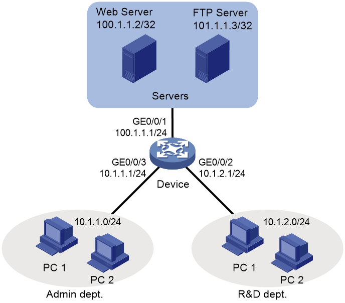
Network configuration
As shown in Figure 3, the network of a company is divided into three parts: Admin dept, R&D dept, and servers. The three parts are connected through the device. Configure ACLs to meet the following requirements:
· The Web server provides HTTP service for only hosts in the Admin dept and allows only TCP connections from hosts (not to hosts).
· The FTP server provides FTP service for only hosts in the R&D dept. The TCP initiator is not limited when the host and the FTP server communicate.
Software versions used
This configuration example was created and verified on Release 9141P16 of the MSR2630E-X1 router.
Analysis
· To allow TCP connections only from hosts, specify the established keyword in an advanced ACL rule to match the TCP packets with the ACK or RST bit set.
· Typically, the TCP initiator uses ports greater than 1023. Permit the Web server-to-host packets with a TCP port greater than 1023 and with the ACK or RST bit set. Deny all other packets from the Web server to hosts.
· To filter FTP packets, deny both FTP data packets (with TCP port 20) and FTP control packets (with TCP port 21).
· To filter HTTP packets, deny the packets with destination TCP port 80.
Procedures
1. Assign IP addresses to interfaces:
# Assign an IP address to GigabitEthernet 0/0/1.
[Device] interface gigabitethernet 0/0/1
[Device-GigabitEthernet0/0/1] ip address 100.1.1.1 24
# Assign IP addresses to other interfaces. (Details not shown.)
2. Configure packet filtering for the Admin dept:
# Create IPv4 advanced ACL 3000.
<Device> system-view
[Device] acl number 3000
# Create a rule to permit the TCP packets with source IP address 100.1.1.2, a destination IP address on the 10.1.1.0/24 network, a destination TCP port greater than 1023, and with the ACK or RST bit set.
[Device-acl-ipv4-adv-3000] rule permit tcp established source 100.1.1.2 0 destination 10.1.1.0 0.0.0.255 destination-port gt 1023
# Create a rule to deny the TCP packets with a source IP address 100.1.1.2 on the 10.1.1.0/24 network and a destination IP address on the 10.1.1.0/24 network.
[Device-acl-ipv4-adv-3000] rule deny tcp source 100.1.1.0 0.0.0.255 destination 10.1.1.0 0.0.0.255
# Create a rule to deny the FTP packets with source IP address 100.1.1.3.
[Device-acl-ipv4-adv-3000] rule deny tcp source 100.1.1.3 0 source-port range 20 21
[Device-acl-ipv4-adv-3000] quit
# Apply ACL 3000 to filter the outgoing packets on GigabitEthernet 0/0/3.
[Device] interface gigabitethernet 0/0/3
[Device-GigabitEthernet0/0/3] packet-filter 3000 outbound
[Device-GigabitEthernet0/0/3] quit
3. Configure packet filtering for the R&D dept:
# Create IPv4 advanced ACL 3001, and configure a rule to deny the HTTP packets with source IP address 101.1.1.2.
[Device] acl number 3001
[Device-acl-ipv4-adv-3001] rule deny tcp source 101.1.1.2 0 source-port eq 80
[Device-acl-ipv4-adv-3001] quit
# Apply IPv4 advanced ACL 3001 to filter the outgoing packets on GigabitEthernet 0/0/2.
[Device] interface gigabitethernet 0/0/2
[Device-GigabitEthernet0/0/2] packet-filter 3001 outbound
[Device-GigabitEthernet0/0/2] quit
Verifying the configuration
# Use the display packet-filter command to display ACL application information for packet filtering.
[Device] display packet-filter interface outbound
Interface: GigabitEthernet0/0/2
Outbound policy:
IPv4 ACL 3001
IPv4 default action: Permit
Interface: GigabitEthernet0/0/3
Outbound policy:
IPv4 ACL 3000
IPv4 default action: Permit
The output shows that GigabitEthernet 0/0/2 and GigabitEthernet 0/0/3 have been successfully applied with an ACL for packet filtering.
# Execute the telnet 101.1.1.3 21 command on a host in the Admin dept to identify whether it can access port 21 of the FTP server.
C:\>telnet 101.1.1.3 21
Connecting To 101.1.1.3...Could not open connection to the host, on port 21:
Connect failed
C:\>
The output shows that the host cannot access port 21.
# Set folder sharing on a host in the Admin dept, and ping the host from the Web server. The ping operation succeeds, but the shared file cannot be visited.
C:\>ping 10.1.1.110
Pinging 10.1.1.110 with 32 bytes of data:
Reply from 10.1.1.110: bytes=32 time=2ms TTL=128
Reply from 10.1.1.110: bytes=32 time=14ms TTL=128
Reply from 10.1.1.110: bytes=32 time=1ms TTL=128
Reply from 10.1.1.110: bytes=32 time=1ms TTL=128
Ping statistics for 10.1.1.110:
Packets: Sent = 4, Received = 4, Lost = 0 (0% loss),
Approximate round trip times in milli-seconds:
Minimum = 1ms, Maximum = 14ms, Average = 4ms
C:\>
# Execute the telnet 100.1.1.2 80 command on a host in the R&D dept to identify whether it can access port 80 of the Web server.
C:\>telnet 100.1.1.2 80
Connecting To 100.1.1.2...Could not open connection to the host, on port 80:
Connect failed
C:\>
The output shows that the host cannot access port 80.
Configuration files
#
interface GigabitEthernet0/0/1
port link-mode route
combo enable copper
ip address 100.1.1.1 255.255.255.0
#
interface GigabitEthernet0/0/2
port link-mode route
combo enable copper
ip address 10.1.2.1 255.255.255.0
packet-filter 3001 outbound
#
interface GigabitEthernet0/0/3
port link-mode route
combo enable copper
ip address 10.1.1.1 255.255.255.0
packet-filter 3000 outbound
#
acl number 3000
rule 0 permit tcp source 100.1.1.2 0 destination 10.1.1.0 0.0.0.255 destination
-port gt 1023 established
rule 5 deny tcp source 100.1.1.0 0.0.0.255 destination 10.1.1.0 0.0.0.255
rule 10 deny tcp source 100.1.1.3 0 source-port range ftp-data ftp
#
acl number 3001
rule 0 deny tcp source 100.1.1.2 0 source-port eq www
Related documentation
· ACL and QoS Configuration Guide in H3C MSR1000[2600][3600] Routers Configuration Guides(V9)
· ACL and QoS Command Reference in H3C MSR1000[2600][3600] Routers Command References(V9)